1
Optimal Multiuser Transmit Beamforming: A Difficult Problem with a Simple Solution Structure Emil Bj¨ornson, Mats Bengtsson, and Bj¨orn Ottersten
Transmit beamforming is a versatile technique for signal transmission from an array of N antennas to one or multiple users [1]. In wireless communications, the goal is to increase the signal power at the intended user and reduce interference to non-intended users. A high signal power is achieved by
arXiv:1404.0408v2 [cs.IT] 23 Apr 2014
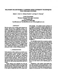
transmitting the same data signal from all antennas, but with different amplitudes and phases, such that the signal components add coherently at the user. Low interference is accomplished by making the signal components add destructively at non-intended users. This corresponds mathematically to designing beamforming vectors (that describe the amplitudes and phases) to have large inner products with the vectors describing the intended channels and small inner products with non-intended user channels. If there is line-of-sight (LoS) between the transmitter and receiver, beamforming can be seen as forming a signal beam toward the receiver; see Figure 1. Beamforming can also be applied in non-LoS scenarios, if the multipath channel is known, by making the multipath components add coherently or destructively. Since transmit beamforming focuses the signal energy at certain places, less energy arrives to other places. This allows for so-called space-division multiple access (SDMA), where K spatially separated users are served simultaneously. One beamforming vector is assigned to each user and can be matched to its channel. Unfortunately, the finite number of transmit antennas only provides a limited amount of spatial directivity, which means that there are energy leakages between the users which act as interference. While it is fairly easy to design a beamforming vector that maximizes the signal power at the intended user, it is difficult to strike a perfect balance between maximizing the signal power and minimizing the interference leakage. In fact, the optimization of multiuser transmit beamforming is generally a nondeterministic polynomial-time (NP) hard problem [2]. Nevertheless, this lecture shows that the optimal transmit beamforming has a simple structure with very intuitive properties and interpretations. This structure provides a theoretical foundation for practical low-complexity beamforming schemes. R ELEVANCE Adaptive transmit beamforming is key to increased spectral and energy efficiency in next-generation wireless networks, which are expected to include very large antenna arrays [3]. In light of the difficulty to compute the optimal multiuser transmit beamforming, there is a plethora of heuristic schemes. Although each scheme might be optimal in some special case, and can be tweaked to fit other cases, these heuristic c
2014 IEEE. Personal use of this material is permitted. Permission from IEEE must be obtained for all other uses, in any current or future media, including reprinting/republishing this material for advertising or promotional purposes, creating new collective works, for resale or redistribution to servers or lists, or reuse of any copyrighted component of this work in other works. This lecture note has been accepted for publication in IEEE Signal Processing Magazine. Supplementary downloadable material is available at https://github.com/emilbjornson/optimal-beamforming, provided by the authors. The material includes Matlab code that can reproduce all simulation results. Contact
[email protected] for further questions about this work.
2
User 1
Beam 1
Beam 2
User 2
Transmitter
Fig. 1: Visualization of transmit beamforming in an LoS scenario. The beamforming is adapted to the location of the intended user, such that a main-lobe with a strong signal power is achieved toward this user while the side-lobes that cause interference to other non-intended users are weak. schemes generally do not provide sufficient degrees of freedom to ever achieve the optimal performance. The main purpose of this lecture is to provide a structure of optimal linear transmit beamforming, with a sufficient number of design parameters to not lose optimality. This simple structure provides many insights and is easily extended to take various design constraints of practical cellular networks into account. P REREQUISITES The readers require basic knowledge in linear algebra, communication theory, and convex optimization. P ROBLEM (P1): P OWER M INIMIZATION WITH SINR C ONSTRAINTS We consider a downlink channel where a base station (BS) equipped with N antennas communicates with K single-antenna users using SDMA. The data signal to user k is denoted sk ∈ C and is normalized to unit power, while the vector hk ∈ CN ×1 describes the corresponding channel. The K different data signals are separated spatially using the linear beamforming vectors w1 , . . . , wK ∈ CN ×1 , where wk is associated with user k. The normalized version
wk kwk k
is called the beamforming direction and points out
a direction in the N -dimensional vector space—note that it only corresponds to a physical direction in LoS scenarios. The squared norm kwk k2 is the power allocated for transmission to user k. We model the received signal rk ∈ C at user k as rk =
hH k
K X
! w i si
+ nk
(1)
i=1
where nk is additive receiver noise with zero mean and variance σ 2 . Consequently, the signal-to-noiseand-interference ratio (SINR) at user k is SINRk = P i6=k
1 2 2 |hH |hH k wk | k wk | σ2 P = . 1 2 2 2 |hH |hH k wi | + σ k wi | + 1 σ2
(2)
i6=k
We use the latter, noise-normalized expression in this lecture since it emphasizes the impact of the noise. The transmit beamforming can be optimized to maximize some performance utility metric, which is generally a function of the SINRs. The main goal of this lecture is to analyze a general formulation of
3
such a problem, defined later as Problem (P2), and to derive the structure of the optimal beamforming. As a preparation toward this goal, we first solve the relatively simple power minimization problem K X
minimize w1 ,...,wK
kwk k2
(P1)
k=1
SINRk ≥ γk .
subject to
The parameters γ1 , . . . , γK are the SINRs that each user shall achieve at the optimum of (P1), using as little transmit power as possible. The γ-parameters can, for example, describe the SINRs required for achieving certain data rates. The values of the γ-parameters are constant in (P1) and clearly impact the optimal beamforming solution, but we will see later that the solution structure is always the same.
S OLUTION TO P ROBLEM (P1) The first step toward solving (P1) is to reformulate it as a convex problem. The cost function
PK
k=1
kwk k2
is clearly a convex function of the beamforming vectors. To extract the hidden convexity of the SINR constraints, SINRk ≥ γk , we make use of a trick from [4]. We note that the absolute values in the SINRs in (2) make wk and eθk wk completely equivalent for any common phase rotation θk ∈ R. Without loss of optimality, we exploit this phase ambiguity to rotate the phase such that the inner product hH k wk is p H H 2 real-valued and positive. This implies that |hk wk | = hk wk ≥ 0. By letting