Jul 14, 2009 - To perform a simulation, insilicoIDE generates C++ source code based on a biophysical ... In this paper we focus on the Runge-Kutta method.
IPSJ Online Transactions
Vol. 2
149–161 (July 2009)
Regular Paper
Optimization Techniques for Parallel Biophysical Simulations Generated by insilicoIDE Eric M. Heien,†1 Yoshiyuki Asai,†2 Taishin Nomura†3 and Kenichi Hagihara†1 Recent work in biophysical science increasingly focuses on modeling and simulating human biophysical systems to better understand the human physiome. One program to generate such models is insilicoIDE. These models may consist of thousands or millions of components with complex relations. Simulations of such models can require millions of time steps and take hours or days to run on a single machine. To improve the speed of biophysical simulations generated by insilicoIDE, we propose techniques for augmenting the simulations to support parallel execution in an MPI-enabled environment. In this paper we discuss the methods involved in efficient parallelization of such simulations, including classification and identification of model component relationships and work division among multiple machines. We demonstrate the effectiveness of the augmented simulation code in a parallel computing environment by performing simulations of large scale neuron and cardiac models.
1. Introduction Encouraged by the success of the Human Genome Project, international efforts to model the human physiome are beginning to take shape. These efforts include work by the International Union of Physiological Sciences (IUPS) Physiome Project 1) , National Simulation Resource (NSR) Physiome Project 2) and the in silico Medicine initiative 3) . The goal of these projects is to create in silico (i.e., computer based) multi-level and multi-timescale integrated models of human cells, organs and systems 4) . †1 Department of Computer Science, Graduate School of Information Science and Technology, Osaka University †2 The Center for Advanced Medical Engineering and Informatics, Osaka University †3 Department of Mechanical Science and Bioengineering, Graduate School of Engineering Science, Osaka University
149
One goal of modeling biophysical systems is to perform numerical simulations based on the models. These simulations can help researchers understand complex physiological phenomenon, such as the effect of various drugs in causing cardiac arrest 5),6) . One environment for modeling such systems is the insilicoIDE program 7),8) . With insilicoIDE, simulations are performed by exporting the biophysical model and control code as a C++ language source file. The source is compiled and executed on a target platform to maximize computational speed. However, simulations of large models may require hours or days to complete on a single computer. For this reason, we added parallel computing support to the simulations generated by insilicoIDE. In this paper we describe the techniques used to generate efficient parallel simulations of biophysical models from insilicoIDE. There are currently numerous software packages for performing biological modeling and simulation. At the molecular scale, GROMACS 9) is used for fast parallel simulation of biomolecular systems. Stochastic simulators allow for probabilistic simulations of biomolecular processes 10) , and discrete event simulations 11),12) are also used for general biophysical modeling and simulation. However, these types of simulations target different models than insilicoIDE. There are numerous packages for modeling and simulating biological systems at a cellular or biochemical pathway level 13)–20) , though none of these support parallel simulation needed for large models. Several specialized projects deal with large scale parallel simulation of specific parts of the human physiome, including neuron networks 21)–24) and heart simulation using morphological models 5) . Although there are a wide range of tools for biological modeling, few offer parallel computing support for large scale model simulation. To the best of our knowledge, the only software platform currently targeting parallel simulation of general large scale multi-level physiome models is insilicoIDE. In this paper, we describe the techniques used to efficiently parallelize simulations of biophysical models created by insilicoIDE. Originally insilicoIDE supported only serial simulation on a single machine, however, parallel simulations are now possible using the techniques described below. Although these techniques are applied to insilicoIDE, they can be used in any biophysical simulation with a similar model structure. In Section 2 we describe the model creation
c 2009 Information Processing Society of Japan �
150
Optimization Techniques for Parallel Biophysical Sims. Generated by insilicoIDE
environment and the biophysical simulations it generates. Section 3 details the techniques used to generate efficient parallel simulations of general biophysical models. Section 4 describes experimental results for parallel simulations created by insilicoIDE. We close with our conclusions and future work in Section 5. 2. insilicoIDE In this section we describe insilicoIDE, a graphical environment for creating multi-scale models of biophysical systems. The structure of the biophysical models is described in Section 2.1. Section 2.2 details how insilicoIDE generates simulation code for a model and what type of calculations the simulation performs. 2.1 Biophysical Models In insilicoIDE, biophysical models are composed of “modules” that represent functional biological elements such as membranes, cells, organs, etc. The modules are connected by “edges” representing structural or logical relationships. Edges allow modular, hierarchical, and/or network representations in a model. For example, a module representing intracellular ion concentration may be connected to a cell membrane module, which connects to an extracellular ion concentration module. Modules contain any number of user specified functions, static parameters and/or dynamic states. They also may include morphological data describing, for example, the bone structure or heart topology related to a model. However, parallelization involving the morphological data is currently not supported and we ignore it. The models are stored in the insilicoML format. insilicoML is a XML based description language for multi-level and multi-scale models of physiological functions. More details on the structure and organization of models are available in Ref. 25). For the purposes of this paper, the key module elements are parameters, states and functions. Static parameters are values that do not change during the course of the simulation, for example, the viscosity of water or the Faraday constant. Dynamic states represent values that change over time governed by ordinary differential equations (ODEs). An example of a dynamic state is the ion concentration in a cell, changing based on the inflow and outflow of ions. Functions represent mathematical functions used to simplify modeling. An example of
IPSJ Online Transactions
Vol. 2
149–161 (July 2009)
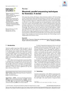
Fig. 1 insilicoIDE model of 8 connected Rybak brain stem respiratory neurons.
module functions are the ionic channel current functions in the Hodgkin-Huxley model 26) . Biophysical models are created by constructing and linking modules together. A state or function in one module may use the value of a state or function in any module it is linked to. Figure 1 shows a sample model with 8 modules representing Rybak brain stem respiratory neurons 27) . In this model, each neuron module contains numerous submodules representing ion channels, membranes, etc. 2.2 Biophysical Simulation To perform a simulation, insilicoIDE generates C++ source code based on a biophysical model. This source code contains classes representing each module and control code to perform the simulation. Each module class contains variables representing states and parameters. The classes also contain functions that calculate the states and functions of the module for given inputs. insilicoIDE simulations update states using either the Euler or Runge-Kutta approximation method. In this paper we focus on the Runge-Kutta method because of its substantially higher accuracy and computational requirements. The Runge-Kutta fourth order method is used to approximate the solution over a series of T time steps each of length h, both specified by the user. Figure 2 shows pseudocode of simulation execution. After initialization, the program performs T simulation steps. Each step involves computing the Runge-
c 2009 Information Processing Society of Japan �
151
Optimization Techniques for Parallel Biophysical Sims. Generated by insilicoIDE 1: Create modules with functions F and states S0 2: step = 0 3: while step < T do 4: k0 = Sstep 5: for i in [1, 4] do 6: ki = F (ki−1 ) 7: end for 8: Sstep+1 = Sstep + 16 k1 + 13 k2 + 13 k3 + 16 k4 9: step += 1 10: Write Sstep values to a log file 11: end while Fig. 2 Pseudocode of insilicoIDE simulations.
Kutta method values k1 , k2 , k3 , k4 and using these to approximate the solution to the state ODEs. 3. Parallel Code Generation Here we describe the techniques used by insilicoIDE to perform fast parallel simulations for arbitrary models. A simple way of performing a parallel simulation is to evenly divide modules among compute nodes. Sophisticated methods involve minimizing communication by using a graph partitioning scheme to divide the simulation. However, these methods can be inefficient because of complex interactions not apparent from the model. Figure 3 shows a graph of an example model with four modules and their data dependencies. This graph contains vertices representing state and function calculations, and edges representing dependencies between these calculations. For simplicity, each function and state is considered to require the same amount of computation. A work division for two nodes (X and Y) based on graph partitioning would assign modules A and C to node X and modules B and D to node Y. Table 1 shows the pseudocode to perform one simulation step of this model. There are several problems that affect the efficiency of this simulation. First, due to the nature of the model, multiple communication phases occur (steps 1, 3, 4 and 6). Second, several steps (5, 7 and 8) leave one of the processors idle. Because of this, the overall simulation speed is affected. This problem occurs because the work partitioning does not distinguish between functions and states, and does not capture the true dependencies of each module. To improve the
IPSJ Online Transactions
Vol. 2
149–161 (July 2009)
Fig. 3 A sample model with four modules A, B, C and D. The modules are divided between two nodes, X and Y. The arrows indicate data dependencies.
Table 1 The steps needed to perform one simulation time step for the model in Fig. 3. Step 1 2 3 4 5 6 7 8
Node X Send R, S to Y Evaluate J(S) Receive I(R) Send J(S) to Y (none) Receive G(S) Evaluate F(S) Approx. dS , dR dt dt
Node Y Receive R, S Evaluate I(R), H(S) Send I(R) to X Receive J(S) Evaluate G(S) Send G(S) to X (none) (none)
simulation, we modify the graph to distinguish dependencies between state and function vertices. In this section, we present techniques for improving computational speed based on model analysis. First in Section 3.1 we examine the types of module data dependencies. Section 3.2 illustrates how this dependence information is used to improve speed by minimizing computation and communication. The division of work among multiple machines for minimum communication is described in Section 3.3.
c 2009 Information Processing Society of Japan �
152
Optimization Techniques for Parallel Biophysical Sims. Generated by insilicoIDE
3.1 Module Dependencies In the parallel simulation, the fundamental unit of work distribution among computing nodes is the module. We optimize the simulation speed through analysis of data dependencies among modules. As described in Section 2.1, a module may depend on an arbitrary number of modules in multiple ways. insilicoIDE analyzes these dependencies when generating the simulation, and uses the analysis to optimize the parallel simulation. The analysis requires no user assistance and takes a small fraction of the total time to generate a simulation. Dependencies can be classified into four categories described in the following sections: 3.1.1 Function ← Function Function ← Function dependencies occur when the evaluation of function F requires the output value of function G, denoted as F ← G. Naturally there can be no circular dependencies among functions. However, there may be nested dependencies spanning multiple modules, in which case all the dependent functions are recorded. In Fig. 3, one Function ← Function dependence is F ← G, H, J. To record Function ← Function dependencies, insilicoIDE creates a directed acyclic graph (DAG) based on the immediate dependencies of each function. Since functions are used to update states, the DAG is referenced when determining State ← Function dependencies. This gives a better estimate of the computational cost of a state. 3.1.2 State ← Function State ← Function dependencies occur when the update of a state S requires the output of a function F , denoted S ← F . Because of Function ← Function dependencies, a state update may depend on more functions than are immediately obvious in the ODE. Once immediate State ← Function dependencies are determined, the DAG generated from Function ← Function dependence analysis is referenced to determine the entire set of functions needed for a state update. For example, if S ← F and F ← G then the complete dependence relation is S ← F, G. In Fig. 3, S ← F is a direct dependence, but the entire set of dependencies is S ← F, G, H, J. 3.1.3 Function ← State Function ← State dependencies occur when evaluation of a function F requires a state S as input, denoted as F ← S. Using this information can decrease
IPSJ Online Transactions
Vol. 2
149–161 (July 2009)
computation and communication time. For example, if F ← S and T ← F for states S and T , then communication and computation can be reduced by placing the modules containing S and T on the same computing node. In Fig. 3, an example Function ← State dependence is I ← R. 3.1.4 State ← State State ← State dependencies occur when the update of state S requires the value of state T , denoted as S ← T . Unlike Function ← Function dependencies, State ← State dependencies can have circular relationships because state values are updated simultaneously. In other words, if at time t there are states St and Tt with S ← T and T ← S, then the value of St+1 = f (Tt ) and Tt+1 = g(St ). In Fig. 3, an example State ← State dependence is R ← S. 3.2 Using Dependence Information to Improve Simulation Speed The dependence information described in Section 3.1 is used to ensure the correctness of the simulation and to improve simulation speed. Two techniques based on the model analysis are used to decrease total communication and improve total simulation speed. The dependence information is recorded in the simulation C++ source file. State ← Function (implicitly including Function ← Function) and State ← State dependencies are recorded in each module class. This effectively records what states and function evaluations are needed to update the states in each module. Function ← State dependencies are recorded separately from the modules. This is to distinguish Function ← State dependence from State ← State dependence, which is necessary to perform the optimization described in Section 3.2.1. Techniques to improve simulation speed are described in the following two sections: 3.2.1 Redundant Function Evaluation For every simulation time step, each node must evaluate the functions necessary to update the states of its modules. Function dependence information recorded in the modules is referenced so that only the necessary functions are calculated by each node. This way each node will avoid evaluating functions not needed for its state updates. Ideally, states and their dependent functions will be on the same compute node, though this cannot be guaranteed. Function dependencies may span multiple modules, therefore the issue arises of how to handle functions needed by
c 2009 Information Processing Society of Japan �
153
Optimization Techniques for Parallel Biophysical Sims. Generated by insilicoIDE
Fig. 4 An example of redundant function calculation. Functions F and G are evaluated on both nodes 1 and 2 to avoid extra communication between the nodes.
multiple compute nodes. As shown in Table 1, communicating module function evaluations between nodes can slow the simulation. Because function evaluation time is relatively fast compared to communication time in most networks, multiple nodes can redundantly evaluate functions to increase overall speed. Figure 4 gives an example of this. Although Modules A and B are on different compute nodes (nodes 1 and 2, respectively), they both require function F in Module C. To avoid excess communication, both nodes 1 and 2 evaluate F and G independently. By only evaluating necessary functions and redundantly computing functions on multiple nodes, total simulation time is decreased. 3.2.2 State Communication The State ← State and Function ← State dependencies correspond to state communication between modules. An even division of modules among compute nodes can yield balanced computational load to each node, but may result in unbalanced and excessive communication. This is because some modules communicate many states while others communicate relatively few. By recording State ← State and Function ← State dependencies, modules with similar state requirements can be grouped on compute nodes to minimize communication between nodes. In the example from Section 3, the state dependencies are not completely known which leads to poor performance. For example, through the chain of dependencies from Function F to Function H, we see that module A implicitly requires state R for an update of state S, which is not shown in the figure. This technique is detailed in the next section.
IPSJ Online Transactions
Vol. 2
149–161 (July 2009)
3.3 Work Partitioning The unit of work division for a parallel simulation is the module. More specifically, it is the task of updating the states of a module. This includes function calculation and state retrieval from other modules. At the start of the parallel simulation, modules must be partitioned among compute nodes. In this section we explain how modules are divided among compute nodes to maximize simulation speed. Let there be P compute nodes N0 , N1 , . . . , NP −1 performing the simulation. The root node N0 calculates a mapping of D modules M = {M0 , M1 , . . . , MD−1 } to the compute nodes, where each module is assigned to one compute node. To compute this mapping, we represent the simulated model as a graph, with graph vertices corresponding to modules and graph edges corresponding to state dependencies between modules. The graph representing the modules and their state dependencies is generated as follows. The vertices V of the graph correspond to the modules M . A module Mi with state S is connected to a module Mn with state R in two possible cases: 1) S ← R or 2) S ← F and F ← R (using the dependency information described in Section 3.1). This means the new module graph explicitly includes Function ← State dependencies which are not directly evident from the model. This also effectively deletes the Function ← Function and State ← Function dependencies, but only for the purpose of work partitioning (the data are retained in the simulation file). To estimate the true computational cost, each vertex is assigned a weight representing the number of functions needed to update the states at that vertex, or in other words the calculation cost of the module. This is slightly inaccurate because some functions are shared by multiple state calculations, but in our experience it is a reasonable approximation. To obtain a mapping of the modules to the P compute nodes, we use the function M ET IS P artGraphKway from the serial graph partitioning library METIS 28) . This function takes as input a graph and number of partitions P , and returns a mapping of each vertex in the graph to a partition. The mapping is computed with two goals: 1) the sum of weights of vertices in each partition is roughly equal and 2) the total number of edges crossing partitions is minimized. In the simulation, these mapping goals respectively correspond to 1) equal com-
c 2009 Information Processing Society of Japan �
154
Optimization Techniques for Parallel Biophysical Sims. Generated by insilicoIDE Table 2 Steps for simulation of the model in Fig. 5. Step 1 2 3 4
Fig. 5 The model from Fig. 3 after using the techniques described in this paper. The weight of a state refers to the number of function evaluations needed to update the state. The arrows indicate only State dependencies, since Functions are not communicated.
putation at each compute node and 2) minimal communication between nodes. The output of METIS is a mapping of each module to a compute node. Given this mapping, the root node determines for each compute node: 1) which states it must evaluate 2) which functions it must evaluate 3) which states it must send/receive to/from which processors. Finally, the root node sends this information to every node and the simulation begins. Figure 5 shows the effect of applying the techniques to the original example model. The graph in Fig. 3 becomes the graph in Fig. 5 through a series of steps which preserve simulation correctness. First, State ← State and State ← Function dependencies are left intact. Next, Function ← Function dependencies are removed and noted implicitly through the weights of each module. The dependency information is retained in the simulation to ensure correct calculation, but for communication it is ignored. In Fig. 5, Module A has weight 5 because it represents the calculation of 1 state and 4 functions (F, G, H, J). Module C has weight 2 because it represents the calculation of 1 state and 1 function. Finally, Function ← State dependencies are handled. We can treat the state dependen-
IPSJ Online Transactions
Vol. 2
149–161 (July 2009)
Node X Send S to Y Receive R Evaluate H, J, G, F Approximate dS dt
Node Y Receive S Send R to X Evaluate I Approximate dR dt
cies of function F as the union of all state dependencies of its children (functions G, J, H). This means that any node which calculates F must receive the states needed to calculate its children and ensure simulation correctness. Therefore, the previous dependency H ← R is transformed into the dependency F ← R. In the new graph, only state communication edges exist because function calculation is performed locally on each node. Although modules C and D belong to node Y, the evaluation of functions J and H actually occurs on node X. Modules B and D have weight 0 because they do not perform any state updates. The resulting simulation steps in Table 2 show a decrease in complexity, communication and idle processor time. With the techniques proposed in this paper, the simulation is greatly simplified and can be performed in 3 basic stages: communication, function evaluation and state calculation. 4. Experiments To confirm the effectiveness of our techniques for optimizing simulations from insilicoIDE, we performed experiments in parallel computing environments. In Section 4.1 we describe the setup for the experiments and the models used in the experiments. Section 4.2 details the effect of our techniques on communication in the simulations, while Section 4.3 examines the cost of redundant function computation. Finally, in Section 4.4 we show the runtime of the simulations in parallel computing environments. 4.1 Setup The simulations were performed using five biophysical models. The first model is of eight connected neurons based on the Rybak model of respiratory neurons 27) and is referred to as “Respiratory”. The second model is of a spinal motor rhythm generator network 29) and is referred to as “Motor”. Models three through five represent grids of myocardial (heart muscle) cells 30) in a 5x5 grid (“Cardiac5”), a
c 2009 Information Processing Society of Japan �
155
Optimization Techniques for Parallel Biophysical Sims. Generated by insilicoIDE Table 3 Simulation model details. Model Name Respiratory Motor Cardiac5 Cardiac10 Cardiac20
Modules 1209 3781 740 2980 11960
States 921 2244 200 800 3200
Functions 2264 3960 830 3360 13520
10x10 grid (“Cardiac10”) and a 20x20 grid (“Cardiac20”). Details of each model are shown in Table 3. For each model, the simulation was run for T = 10000 time steps. To test the parallel simulation, we used two environments - a multicore machine and a networked cluster. The multicore machine is a dual quad core processor Intel Xeon 2.83 GHz with 4 GB of RAM. The cluster consists of 16 HP ProLiant G2 machines, each with dual 2.8 GHz Xeon processors and 2 GB of RAM connected by Gigabit ethernet. 4.2 Simulation Communication One key argument in this paper is that using the techniques described in Section 3 will reduce communication by simplifying the model (e.g. Fig. 3 to Fig. 5). To confirm this, we performed an analysis of communication patterns using the original model versus the modified model. The results of this analysis are presented in Fig. 6. For each model, these figures show the average number of states and functions communicated between nodes, and the number of communication phases needed per simulation time step. In this paper, a communication phase is a set of MPI sends and receives between nodes that is uninterrupted by calculation. In all simulations, the communication data size of a state and function result are the same (8 bytes). As seen in Fig. 6 (a), the modified model communicates more states than the original model for most configurations when simulating the respiratory neuron model. However, the tradeoff is that the original model must perform up to 4 communication phases per simulation time step. By simplifying the model, some additional state communication is added, but overall communication time is decreased through fewer communication phases. It is also worth noting the low communication when using 2, 4 or 8 nodes - this is because the respiratory
IPSJ Online Transactions
Vol. 2
149–161 (July 2009)
model breaks cleanly into 8 pieces. Figure 6 (b) shows the effect on communication for the motor network simulation. This model is different from the respiratory model in that many of the components are strongly connected by states. In this case, the original simulation is best performed with very little state communication, though this in turn causes multiple communication phases due to function communication. Also, the number of communication phases stays relatively low regardless of the number of computing nodes, indicating that there is less inter-module functional dependence than in the respiratory model. This also explains why function communication is preferred in the original model simulation, specifically because the modules are not strongly connected by functions. The sudden increase in states when using 11 nodes is due to the structure of the model. Figures 6 (c), (d) and (e) show the effect on communication in the three cardiac cell models. In this case, the grid nature of the model means few communication phases are required because of the independent nature of each grid element (heart cell). However, by eliminating function communication in the modified model, model division follows the grid better than in the original model. This is noticeable, for example, in the Cardiac5 model where using 5 nodes reduces communication in the modified model but increases it in the original model. These figures demonstrate that by removing function dependencies from the model, our techniques often increase the number of state dependencies (e.g., the respiratory model). However, because these states can be calculated independently the number of communication phases is reduced to 1. Furthermore, in many cases the increased state communication is offset by the elimination of function communication, particularly in the cardiac models and the motor network model. The actual effect of the techniques on a given model will vary depending on the model characteristics. 4.3 Redundant Function Computation Section 3.2.1 describes a technique to reduce communication with redundant calculation. Naturally, excessive redundancy will cancel the gain made by decreasing communication. To confirm the gain from redundant calculation, we examined the number of excess function calculations per node. Figure 7 shows the effect of redundant calculation in terms of extra functions calculated and
c 2009 Information Processing Society of Japan �
156
Optimization Techniques for Parallel Biophysical Sims. Generated by insilicoIDE
(a) Respiratory model communication.
(c) Cardiac5 model communication.
(b) Motor network model communication.
(d) Cardiac10 model communication.
(e) Cardiac20 model communication.
Fig. 6 Comparison of communication between original and modified models. Upper graphs show the average number of states/functions sent per node, and lower graphs show the number of communication phases per simulation step.
additional computation time per simulation step. Depending on the model, the effect can vary widely. The respiratory model breaks cleanly into 8 pieces, so there is no redundant computation when using 2, 4 or 8 nodes. Functions in the motor model are not strongly connected so there is generally little or no redundant function calculation. The cardiac grid models also have little or no redundant function calculation when divided among a number of nodes that fits the grid well (e.g., 5 nodes for Cardiac5, 10 nodes for Cardiac10, etc).
IPSJ Online Transactions
Vol. 2
149–161 (July 2009)
Based on the execution of a serial simulation, we estimate the average time to compute a function as 0.32 µs, which means redundant function calculation adds at worst 0.68 µs of computation to each simulation time step. This is well under the latency of most communication channels, for example Myrinet has a minimum latency of 2.6 µs and Infiniband has a minimum latency of 1.1 µs. Therefore, using redundant calculation is an effective way to reduce overall simulation time. 4.4 Simulation Execution Figures 8 and 9 show the results of performing the model simulations in the
c 2009 Information Processing Society of Japan �
157
Optimization Techniques for Parallel Biophysical Sims. Generated by insilicoIDE
Fig. 7 Average number of redundant function evaluations per simulation time step.
two parallel environments. These figures show the total simulation execution time for different numbers of nodes, the speedup of the computational part of the simulation, and the total speedup. Initialization time (including graph partitioning and work division) was negligible and is not included. We found little deviation in the run times for multiple executions, so these figures represent only a single execution. Figure 8 shows simulation performance in the multicore environment. The simulations scale very well on multicore machines, achieving a nearly linear speed increase in both function and state computation. Total simulation speed approaches a linear speedup for all but the Cardiac5 model, likely because of its small size. The large myocardial simulation (Cardiac20, Fig. 8 (e)) shows a notable superlinear speed increase, likely due to improved cache performance. As expected, communication time is minimal on multicore machines, though for smaller models it can become problematic for large numbers of nodes. With larger models, communication accounts for a relatively small part of simulation time and more nodes will yield better performance. Figure 9 shows simulation performance in the cluster environment. In this environment there is greater sensitivity to communication because of the network and thus simulations do not scale as well. For simulations performed on the cluster, communication dominates as the number of nodes increases, particularly for smaller models. As seen in Fig. 9 (a) and Fig. 9 (b), performance peaks around
IPSJ Online Transactions
Vol. 2
149–161 (July 2009)
16 nodes for the neuron models. The cardiac models scale poorly on the cluster due to their size, especially Cardiac5. However, the calculation of functions and states scales well for larger models as shown in the bottom graphs. The Motor and Cardiac20 simulations achieve a slightly superlinear computation speedup with multiple nodes. 5. Conclusions In this paper, we detailed techniques for improving parallel simulations of biophysical models generated by the insilicoIDE program. We explained how we used automated analysis of the models to improve computational speed and minimize communication in the parallel simulation. Finally, we demonstrated the effectiveness of these techniques by performing simulations of multiple types of models with thousands of states/functions. Current biophysical modeling systems rarely support parallel simulation of the models, often only for a particular type of model (neuron, cardiac cell, etc.). To the best of our knowledge, this paper is the first to detail parallel simulation of general multilevel biophysical models based on ordinary differential equations. This type of simulation is crucial for progress to be made in the types of large scale modeling and simulation needed in worldwide physiome projects. Fundamentally, this research demonstrates a method for determining data dependence between computations (the functions and states), then using this infor-
c 2009 Information Processing Society of Japan �
158
Optimization Techniques for Parallel Biophysical Sims. Generated by insilicoIDE
(a) Respiratory simulation times.
(c) Cardiac5 simulation times.
(b) Motor network simulation times.
(d) Cardiac10 simulation times.
(e) Cardiac20 simulation times.
Fig. 8 Simulations performed on multicore machine.
mation to minimize dependencies between computing nodes. This has the effect of reducing communication and accelerating the computation. This technique is potentially applicable in other fields when performing large scale simulations of irregular models. The redundant function calculation technique could be improved by using multiobjective graph partitioning to minimize both the amount of state communication and redundant function calculation. For the Rybak model in this paper, the
IPSJ Online Transactions
Vol. 2
149–161 (July 2009)
amount of redundant function calculation is small enough to make this unnecessary. However, for more complicated models with complex function relations, this might be worth investigating. In addition, using ordered calculation to improve cache efficiency may also improve state calculation speed. In future work we plan to extend insilicoIDE to support parallel simulation of models using partial differential equations, morphological data and agent-based systems. The complexity of these may require a separate simulator program
c 2009 Information Processing Society of Japan �
159
Optimization Techniques for Parallel Biophysical Sims. Generated by insilicoIDE
(a) Respiratory neuron simulation times.
(c) Cardiac5 simulation times.
(b) Motor network simulation times.
(d) Cardiac10 simulation times.
(e) Cardiac20 simulation times.
Fig. 9 Simulations performed on cluster.
rather than a compiled simulation. However, the techniques described in this paper are still applicable to such a system, as well as other parallel biophysical simulators. Acknowledgments We thank Keisuke Tominaga from Osaka University for developing the cardiac models for this research. We also thank Derrick Kondo from INRIA Grenoble for his helpful comments. This work was supported in part by Research Fellowship (19·55401) and Grant-in-Aid for Scientific Research
IPSJ Online Transactions
Vol. 2
149–161 (July 2009)
(A)20240002 from the Japan Society for the Promotion of Science, and by the Global COE Program “in silico medicine” at Osaka University. References 1) Hunter, P.J.: The IUPS Physiome Project: A framework for computational physiology, Prog. Biophys. Mol. Biol., Vol.85, No.2-3, pp.551–569 (2004). 2) Bassingthwaighte, J.B.: Strategies for the physiome project, Ann. Biomed. Eng.,
c 2009 Information Processing Society of Japan �
160
Optimization Techniques for Parallel Biophysical Sims. Generated by insilicoIDE
Vol.28, No.8, pp.1043–1058 (2000). 3) Nomura, T.: Challenges of Physiome Projects, IEEJ Trans. EIS, Vol.127, No.10, pp.1491–1497 (2007). 4) McCulloch, A.D. and Huber, G.: Integrative biological modelling in silico, Novartis Found. Symp., Vol.247, pp.4–19; discussion 20–25, 84–90, 244–252 (2002). 5) Nickerson, D., Nash, M., Nielsen, P., Smith, N. and Hunter, P.: Computational multiscale modeling in the IUPS Physiome Project: Modeling cardiac electromechanics, IBM J. Res. Dev., Vol.50, No.6, pp.617–630 (2006). 6) Noble, D.: Computational models of the heart and their use in assessing the actions of drugs, J. Pharmacol. Sci., Vol.107, No.2, pp.107–117 (2008). 7) Physiome Website. http://physiome.jp/ (2008). 8) Kawazu, T., Nakanishi, M., Suzuki, Y., Odai, S. and Nomura, T.: A Platform for in silico Modeling of Physiological Systems, Engineering in Medicine and Biology Society, 2007, EMBS 2007, 29th Annual International Conference of the IEEE, pp.1394–1397 (2007). 9) Hess, B., Kutzner, C., van der Spoel, D. and Lindahl, E.: GROMACS 4: Algorithms for highly efficient, load-balanced, and scalable molecular simulation, J. Chem. Theory Comput., Vol.4, No.3, pp.435–447 (2008). 10) Nov`ere, N.L. and Shimizu, T.S.: STOCHSIM: modelling of stochastic biomolecular processes, Bioinformatics, Vol.17, No.6, pp.575–576 (2001). 11) Ghosh, S., Ghosh, P., Basu, K., Das, S. and Daefler, S.: iSimBioSys: A Discrete Event Simulation Platform for ‘in silico’ study of biological systems, ANSS ’06: Proc. 39th annual Symposium on Simulation (2006). 12) Jeschke, M., Ewald, R., Park, A., Fujimoto, R. and Uhrmacher, A.: A parallel and distributed discrete event approach for spatial cell-biological simulations, ACM SIGMETRICS Performance Evaluation Review, Vol.35, No.4 (2008). 13) Bergmann, F. and Sauro, H.: SBW — a modular framework for systems biology, WSC ’06: Proc. 38th conference on Winter simulation (2006). 14) Cickovski, T., Huang, C., Chaturvedi, R., Glimm, T., Hentschel, H., Alber, M., et al.: A Framework for Three-Dimensional Simulation of Morphogenesis, IEEE/ACM Transactions on Computational Biology and Bioinformatics (TCBB ), Vol.2, No.4 (2005). 15) Demir, S.S.: Interactive cell modeling web-resource, iCell, as a simulationbased teaching and learning tool to supplement electrophysiology education, Ann. Biomed. Eng., Vol.34, No.7, pp.1077–1087 (2006). 16) Funahashi, A., Matsuoka, Y., Jouraku, A., Morohashi, M., Kikuchi, N. and Kitano, H.: CellDesigner 3.5: A versatile modeling tool for biochemical networks, P Ieee, Vol.96, No.8, pp.1254–1265 (2008). 17) Ishii, N., Robert, M., Nakayama, Y., Kanai, A. and Tomita, M.: Toward largescale modeling of the microbial cell for computer simulation, J Biotechnol., Vol.113, No.1-3, pp.281–294 (2004).
IPSJ Online Transactions
Vol. 2
149–161 (July 2009)
18) Loew, L. and Schaff, J.: The Virtual Cell: A software environment for computational cell biology, Trends Biotechnol., Vol.19, No.10, pp.401–406 (2001). 19) Mendes, P.: Biochemistry by numbers: simulation of biochemical pathways with Gepasi 3, Trends Biochem. Sci., Vol.22, No.9, pp.361–363 (1997). 20) Sarai, N., Matsuoka, S. and Noma, A.: simBio: A Java package for the development of detailed cell models, Prog. Biophys. Mol. Bio., Vol.90, No.1-3, pp.360–377 (2006). 21) Ananthanarayanan, R. and Modha, D.: Anatomy of a cortical simulator, SC ’07: Proc. 2007 ACM/IEEE conference on Supercomputing (2007). 22) Djurfeldt, M., Lundqvist, M., Johansson, C., Rehn, M., Ekeberg, O. and Lansner, A.: Brain-scale simulation of the neocortex on the IBM Blue Gene/L supercomputer, Ibm J. Res. Dev., Vol.52, No.1-2, pp.31–41 (2008). 23) Hines, M.L. and Carnevale, N.T.: NEURON: A tool for neuroscientists, The Neuroscientist: A review journal bringing neurobiology, neurology and psychiatry, Vol.7, No.2, pp.123–135 (2001). 24) Plesser, H., Eppler, J., Morrison, A., Diesmann, M. and Gewaltig, M.-O.: Efficient Parallel Simulation of Large-Scale Neuronal Networks on Clusters of Multiprocessor Computers, Euro-Par 2007 Parallel Processing, pp.672–681 (2007). 25) Suzuki, Y., Asai, Y., Kawazu, T., Taniguchi, Y., Heien, E., Hagihara, K., et al.: A Platform for in silico Modeling of Physiological Systems II. CellML Compatibility and Other Extended Capabilities, Conf. Proc. IEEE Eng. Med. Biol. Soc., pp.573– 576 (2008). 26) Hodgkin, A.L. and Huxley, A.: A quantitative description of membrane current and its application to conduction and excitation in nerve, J. Physiol. (Lond ), Vol.117, No.4, pp.500–544 (1952). 27) Rybak, I.A., Paton, J.F. and Schwaber, J.S.: Modeling neural mechanisms for genesis of respiratory rhythm and pattern. I. Models of respiratory neurons, J. Neurophysiol., Vol.77, No.4, pp.1994–2006 (1997). 28) Karypis, G. and Kumar, V.: A Fast and High Quality Multilevel Scheme for Partitioning Irregular Graphs, SIAM J. Sci. Comput., Vol.20, No.1, pp.359–392 (1998). 29) Rybak, I.A., Stecina, K., Shevtsova, N.A. and McCrea, D.A.: Modelling spinal circuitry involved in locomotor pattern generation: insights from the effects of afferent stimulation, J. Physiol-London, Vol.577, No.2, pp.641–658 (2006). 30) Xu, A. and Guevara, M.: Two forms of spiral-wave reentry in an ionic model of ischemic ventricular myocardium, Chaos, Vol.8, No.1, pp.157–174 (1998).
(Received October 3, 2008) (Accepted January 29, 2009) (Released July 14, 2009) (Original version of this article can be found in the IPSJ Transactions on Advanced Computing Systems, Vol.2, No.2, pp.131–143.)
c 2009 Information Processing Society of Japan �
161
Optimization Techniques for Parallel Biophysical Sims. Generated by insilicoIDE
Eric Heien was born in 1979. He received his B.A. in computer science from the University of California, Berkeley in 2002. During this time, he was also involved in the SETI@home and BOINC projects at Berkeley. He is currently working on a Ph.D. in computer science at Osaka University under a research fellowship from the Japan Society for the Promotion of Science. His current research interests are load distribution and scheduling in parallel processing systems, large scale computing on desktop grids and volunteer computing systems, and parallel simulation for in silico physiome research.
Taishin Nomura was born in 1967. He received his Ph.D. in Biophysical Engineering from Osaka University in 1995. He became a professor at the Graduate School of Engineering Science at Osaka University in 2004. His research interests involve nonlinear dynamical system theory and its application to physiological dynamics of cellular membranes, cardiac tissues, human gait and posture control. He is currently a leader of the MEXT global COE program involved in the physiome project at Osaka University. He is a member of JSMBE and IEEE-EMBS.
Yoshiyuki Asai was born in 1975. He received his Master’s degree and Ph.D. from the Graduate School of Engineering Science at Osaka University. During his postdoctoral research he worked at the Neuroheuristic Research Group at the ISI Foundation in Torino, Italy and in Lausanne University, Switzerland. From October 2007 he took up his current position as a specially appointed associate professor at the Center for Advanced Medical Engineering and Informatics in Osaka University. His research interests are development of an IDE for multi-scale physiome modeling, human motor control strategy, and information processing in neural systems.
Kenichi Hagihara was born in 1952. He received his Ph.D. degree in information and computer sciences from Osaka University in 1979. From 1992 to 1993, he was a Visiting Researcher at Maryland University. From 1994 to 2002, he was a Professor in the Department of Informatic and Mathematical Science, Graducate School of Engineering Science, Osaka University. Since 2002, he has been a Professor in the Department of Computer Science, Graduate School of Information Science and Technology, Osaka University. His current research interests are the fundamentals and practical application of parallel processing, particularly GPU and grid computing. He is an ex-director of IPSJ.
IPSJ Online Transactions
Vol. 2
149–161 (July 2009)
c 2009 Information Processing Society of Japan �