Sep 4, 1997 - Parameter Optimisation of a Non-linear Tanker Control System using Genetic Algorithms. Euan W. McGookin. â. , David J. Murray-Smith.
Parameter Optimisation of a Non-linear Tanker Control System using Genetic Algorithms
Â
Euan W. McGookin , David J. Murray-Smith , Yun Li and Thor I. Fossen
Â
Centre for Systems and Control & Dept. of Electronics and Electrical Engineering, University of Glasgow, UK
Department of Engineering Cybernetics, Norwegian University of Science and Technology, Trondheim, Norway
Abstract The optimisation of a non-linear control problem by Genetic Algorithm (GA) is studied in this paper. It involves the performance of a fully autonomous control system for regulating the course keeping manoeuvres of an oil tanker. This control system consists of an autopilot and a Sliding Mode Controller (SMC). The GA is used to optimise the performance of the complete system by optimising the parameters of the SMC.
This paper addresses these issues and has the following structure. Section 2 describes the mathematical model of the tanker used in this optimisation study and outlines the problem of controlling these vessels in general. Section 3 describes the complete control system used in this study (i.e. the autopilot and the control algorithm used). The next section will outline the details of the GA and show the results obtained from this investigation. The final section draws conclusions from the results of this investigation.
1. Introduction
2. Tanker Model
The petroleum industry affects nearly everything and everyone in modern life since the uses of oil are so widespread. Like most other things this comes with a hidden cost through the need to transport crude oil [1-3]. Moving large quantities of oil inevitably involves risks to the environment and in the past few years safety issues have arisen concerning oil tanker navigation and control. These mostly arise from accidents such as the ‘Sea Empress’ disaster which had a considerable impact on the ecosystem of the local environment and will still have an effect for some time to come. As well as the environmental cost, it also presented a major cost to the oil company through loss of revenue, the effective loss of a ship and the clean up operation. In order to avoid such incidences happening it is very important to find ways to control these vessels safely. This is not an easy task since these tankers are large vessels and in the case of super tankers can be in excess of 300m in length. Their size makes them very difficult to manoeuvre and this is not aided by the restricted proportions of the ships’ main heading actuator (the rudder)[1-6]. However, the use of automatic control systems could help to provide an answer to the problem of diminished controllability. Such control systems have to be able to minimise the rudder effort as the ship is manoeuvred. This paper suggests that one way to achieve this is by implementing fully autonomous control systems which replace the pilot/helmsman input with the commands from an autopilot [1-7]. The selection of parameter values for the controller of a system of this kind provides a very interesting problem for the application of Genetic Algorithms (GAs) [8-14]. It is particularly suited since an optimisation criterion is already provided i.e. the minimisation of the rudder actuator usage [6,9].
The vessel considered here is a 304.8 m long, 190,000 dwt oil tanker [1-3]. The propulsion and heading dynamics are represented by a non-linear mathematical model of the following general state space form [4] x� = f (x, u)
(1)
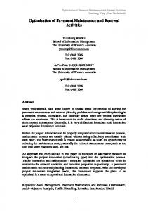
Here x is the state vector and u represents the inputs to the tanker. The states are divided into the kinetic states (defined along the body-fixed axes) and the kinematic states of the system (defined along the earth-fixed inertial reference frame) (see Figure 1)[4]. The kinetic states are surge velocity u, sway velocity v and the yaw rate r. The kinematic components are the yaw (or heading) angle ψ and the earth-fixed x and y coordinates of the tanker (xp and yp). As well as having controllable inputs (i.e. rudder deflection ( δr ) and propeller angular velocity (n (rpm))) this model is dependant on the depth of the water (h) [1]. Therefore it is directly influenced by its external environment. In this study the value for n is 80 rpm (full speed) which gives a surge velocity of 8 ms-1. Body Fixed Co-ordinate System
ψ (yaw angle)
u (surge) δr
r (yaw rate)
v (sway)
(rudder angle)
h (depth) xP XEARTH yP
ZEARTH
Earth Fixed Co-ordinate System YEARTH
Figure 1: Tanker Co-ordinate Systems
Submitted to the 2nd IEE/IEEE International Conference on Genetic Algorithms in Engineering Systems: Innovations and Applications 2-4 September 1997, Glasgow, UK
As well as modelling the dynamics of the entire vessel, this model represents the mechanics of the rudder. It does this by applying rate and maximum amplitude limits to the deflection of the rudder. The rate limit is taken as 2.33 degrees/second and the maximum rudder deflection is 30 degrees [4]. The commanded rudder angle from a control system or the helmsman may be outside this operating envelope. Therefore a distinction must be made between the commanded rudder angle ( δrcom ) and the tanker’s actual rudder angle ( δr ) [1-4]. These limitations on the performance of the rudder are the main reason for the tanker’s limited controllability. From the model and standard fluid dynamics, the amount of turning moment generated by the rudder is dependant on the amount of flow over the rudder [4]. This in turn depends on the surge velocity and the speed of the propeller [1,4]. Both these are relatively small due to the size of the vessel and as a result so is the flow over the rudder and the turning moment it can generate. Therefore it can be concluded that in order to make the tanker turn quickly or to a large heading angle, the rudder deflection may be large and will meet or surpass these limits. When the rudder has saturated like this there is very little that the controller or helmsman can do to correct this and the tanker becomes practically uncontrollable. Therefore it is very important to make sure that the rudder operates well within these limits (particularly the maximum magnitude limit), thus ensuring that there is additional deflection available if more control effort is required. This provides a design criterion for the controller to satisfy. Hence there is a need for a control system which will operate the rudder within its operation envelope and still perform the tasks required. Such a control system is presented below. 3. Tanker Control System The tanker control system is fully autonomous in that it automatically guides the vessel on a predetermined course without human intervention. As long as the course is selected so that it avoids hazardous waters1, the passage of the tanker should be safe and uneventful. This type of tracking manoeuvre is called Course Keeping. There are two fundamental components to this control system i.e. an autopilot [6,7] and a course changing controller [4,5,9], which are configured to the tanker model in the way shown in Figure 2. The individual components carry out the following tasks.
1
Hazards such as shallow water regions where the tanker could run aground
A Line Of Sight (LOS) autopilot [4,7] is used to provide a desired heading reference for the course changing controller to follow. WAYPOINT POSITION (xwp, ywp)
DESIRED HEADING LOS AUTOPILOT
COURSE CHANGING CONTROLLER
WATER DEPTH (h)
δr
TANKER MODEL
STATES (x)
CONTROL SYSTEM
ψ TANKER HEADING ( ) & YAW RATE (r)
TANKER POSITION (xp, yp)
Figure 2: Control System and Tanker Model The Course Changing Controller is an automatic controller which can produce an input signal for the tanker [4,6,7,9-12]. This input makes the tanker heading follow the desired heading produced by the autopilot. The particular type of controller used here is a Sliding Mode Controller (SMC) [4,9-12]. As the name suggests, the course changing controller can be used separately to change the course/heading of the tanker by commands from a pilot /helmsman. It manages this by feeding back the actual tanker heading and comparing it to the commanded heading. If there is a discrepancy in the two then the controller adjusts the rudder deflection until they are the same. When the autopilot is integrated into the controller/tanker system it adds an outer feedback loop which stabilises the tanker position. The addition of an autopilot enables the tanker to keep course accurately which is of particular use in coastal or hazardous waters [1-3]. 3.1 Simple LOS Autopilot This kind of autopilot [4,7] directs the tanker along a predetermined course which is set out prior to autopilot activation. The course is made up of points called waypoints [4,7] which are used to calculate the reference heading angle between the tanker's present position and the waypoint position (see Figure 3). This heading angle ψ ref is obtained from equation (2) [4,7]. The sign convention for this angle defines that positive angles (0O< ψ ref ≤ 180O) are to starboard and negative angles (180O < ψ ref < 0O) are to port. y wp − y p ψ ref = tan −1 x wp − x p
(2)
In equation (2), (xp, yp) are the current position coordinates of the tanker obtained from a Global Positioning System (GPS) and (xwp, ywp) are the waypoint co-ordinates [4,7]. The reference heading is then used to
Submitted to the 2nd IEE/IEEE International Conference on Genetic Algorithms in Engineering Systems: Innovations and Applications 2-4 September 1997, Glasgow, UK
obtain the desired heading response for the controller to track. The autopilot guides the tanker from waypoint to waypoint. Once the tanker comes within a specified XEARTH WAYPOINT
xwp ψ ref
TANKER
xp YEARTH
yp
ywp
heading to the desired response accurately. Hence enabling the tanker to reject the disturbances caused by external factors (e.g. waves) or a change in the operating point of the ship itself [4]. This is particularly useful in the tanker system when meeting the control objective and minimising the rudder usage are both critical. Most SMC are derived from the non-linear state space representation of the system it is to be applied to. Since in this case there is only one input being controlled2, a control law based on a linear representation of the dynamics to be controlled is used [4,7,9]. In order to apply this, the yaw rate (r) and the heading angle ( ψ ) dynamics are decoupled from the entire system (equation (1)) and linearised into the following single input state space equation [4,9]. x� H = A H x H + b H δrcom
Figure 3: Reference Heading Geometry
(3)
The controller is then designed for this linearised subsystem and the control input is applied to the nonlinear model. In this linearised subsystem xH is the state vector, AH is the corresponding system matrix, bH the input matrix and δrcom the input vector (i.e. the rudder input after limitations are applied) [9].
XEARTH TANKER
WAYPOINTS
Using the derivation given in references [4] and [7] the following SMC equation is obtained for the commanded rudder input.
ACCEPTANCE RADII YEARTH
σH δrcom = −k T x H + (h Tb H ) −1 h T x� HD − ηH tanh φH (4)
Figure 4: Waypoint Acquisition distance of the current waypoint, the autopilot acquires the next waypoint position and the tanker heads towards it (see Figure 4). This distance is called the acceptance radius and is typically between one and three boat lengths. The acquisition process is repeated until the tanker reaches its final destination. 3.2 Tanker Controller As mention previously, the controller used in this system is a course changing controller which is regulated by the autopilot. Its purpose is to change the heading of the vessel by manipulation of the rudder. Effectively it will provide the δrcom signal for the tanker model. The particular controller used in this study is from the Sliding Mode Control law. This type of control is a well documented non-linear methodology which is characterised by its switching action [4,7,9-12]. The reason for using this type of controller is that it gives robustness to internal and external changes in the environment. This is mainly due to the switching part of the control law in equation (4) which helps track the
In this equation k is the feedback gain vector for the subsystem, h is the right eigenvector of the desired closed loop system matrix and xHD is the desired heading state vector [9]. The tanh term provides the switching action which characterises SMCs. The magnitude of this switching action is determined by the switching gain ηH and its activity is governed by the sliding surface σ H and the boundary layer thickness φ H [4,9]. For this particular application the controlled output is the heading angle, ψ , which follows the desired heading response in a type of model reference control system. This desired response is the reference supplied by the autopilot. 3.3 Depth Configuration and Waypoint Position In order to simulate this tanker system, an artificial environment has been created which incorporates two 2
The propeller input obeys simple step commands and does not require a complex controller regulate its rotational speed.
Submitted to the 2nd IEE/IEEE International Conference on Genetic Algorithms in Engineering Systems: Innovations and Applications 2-4 September 1997, Glasgow, UK
external factors vital to the system. These are the configuration of the water depth and the waypoint course for the autopilot to follow. The change in depth used in this study allows full advantage to be taken of the tanker model dynamics. The configuration used is illustrated in Figure 5 and is created to represent a change in depth from deep water (500m) to shallow (25m). The deep water area is limited to this Restricted Channel
The acceptance radii, projected course and depth contours are also shown in this figure. It should be noted that the radii of the waypoints in the shallower waters are only one boat length whereas in deeper water it is taken as two boat lengths. The shallow water radii are smaller because of the bank constraints of the channel. This calls for greater acquisition accuracy on behalf of the autopilot since manoeuvrability is constrained. In the deeper water this is not a problem since there is more room to move. 4. GA Implementation and Results
100
4.1 GA Optimisation
- depth (m)
0 -100 -200 -300 -400
Deep Water
-500 4000
6000 3500
5000 3000 2500
4000 2000
3000 1500
x position (m)
1000
2000 500
0
0
In this investigation an elite GA [14] is used which utilises a rank based selection scheme of size 20% [814]. In order for this type of GA to avoid local minima its mutation rate is set a 5%. Elite GAs are used because of their speed of convergence [14] which is very important in this application since the execution time of the tanker system simulation is large.
y position (m)
1000
Table 1: Parameters to be optimised Figure 5: Water Depth Configuration depths. Although the shallowest point is less than the recommended operating depth of about three times the draft [1,2], it is used to investigate the controllability of the vessel if it got into trouble in shallow waters. The shallow waters are restricted by the banks of the channel which are used to limit the manoeuvrability of the tanker in this area Unfortunately the banking effects encountered in such a narrow water channel are not incorporated into the model and could not be investigated here [3]. The course laid out for the autopilot to follow must stay within the bounds of the depth configuration described above. In this case three points are used and their coordinates are illustrated in Figure 6. 4000
Heading Controller Parameters 1st Heading Closed loop pole 2nd Heading Closed loop pole Heading switching gain Heading Boundary Layer Thickness
pH1 pH2 ηH φH
The key controller parameters that the GA tunes in this study are shown in Table 1 [9]. Parameters pH1 and pH2 are two poles of the desired closed loop heading system which has another pole at the origin [4,9]. The other two parameters are described above. In applying this optimisation technique all the values of these parameters are manipulated by the GA and a measure of the cost is calculated using the simulation results obtained from the complete tanker system [8-14]. The GA only accepts parameter solutions which yield smaller cost values. Therefore it is trying to minimise the cost to obtain an optimal solution [8,9].
0m (sea level) 100m
3500
4.2 Cost Function
200m 300m
3000
The cost function used here contains two components as defined by the following equation.
x position (m)
400m 2500
2000
C TOTAL = C PER + C PEN
Waypoints
1500
Acceptance Radii
where CPER is the performance cost of the tanker and CPEN is a penalty cost which depends on the number of waypoints acquired by the autopilot.
1000
Projected Course 500
Depth Contours
Start 0
0
500
1000
1500
2000
2500
3000
3500
y position (m)
Figure 6: Waypoint Course
4000
4500
5000
5500
(5)
6000
The first of these components is a discrete version of integral least squares criterion [6,9] i.e.
Submitted to the 2nd IEE/IEEE International Conference on Genetic Algorithms in Engineering Systems: Innovations and Applications 2-4 September 1997, Glasgow, UK
i
i =0
2
+ (δri ) 2
]
4.3 Results (6)
Here m is the total number of iterations, λ is a weighting factor ( λ = 10 in this case), ∆ψ i is the ith heading angle error between the desired and obtained heading, δri is the ith rudder deflection [6,9]. The weighting factor is needed in this application because the rudder deflection is so large that it would overshadow any improvements in the heading error. This is not a problem with smaller vessels since they respond more readily to small rudder deflections. Since the GA is trying to minimise the value of this function it is easy to see that both ∆ψ and δr will be minimised too. The reasoning behind this selection of elements for the cost function is as follows. The quantity ∆ψ gives an indication of how close the actual heading is to the desired heading, therefore showing how well the controller is operating. The component δr is used to keep rudder actuator movement to a minimum so that it can operate well within the actuators operating limits. This is of particular importance with SM controllers which have a tendency to chatter if the switching gain and boundary layer values are not chosen properly [4,9]. Another advantage of minimising the rudder deflection is the savings in terms of fuel consumption since the resistance to the forward motion is minimised [6]. Since the deflection is minimised, the rudder/hull produces less drag and hence more of the forward force goes to producing a larger surge velocity. As well as the heading and rudder performance provided by equation (6), the number of waypoints (nwp) acquired by the autopilot is counted. Only three waypoints should be acquired in the time interval of the simulation to ensure that the autopilot acquires this number the following penalty function is used to calculate an addition cost value.
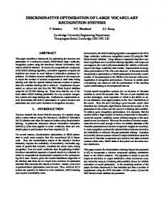
After 100 generations of the GA, typical parameter values (see Table 2) are obtained Table 2: GA Optimised Heading Controller Parameters Heading Controller Parameters 1st Heading Closed loop pole -0.0840 2nd Heading Closed loop pole -0.2001 Heading switching gain 5.4620 Heading Boundary Layer Thickness 6.1770 Rudder Angle (degrees) Heading Error (degrees) Heading Angle (degrees)
∑ [λ (∆ψ )
80 60 40 20 0 -20 0
100
200
300
400
500
600
700
800
500
600
700
800
500
600
700
800
time (s) 0.4 0.2 0 -0.2 -0.4 -0.6 0
100
200
300
400
time (s) 10 0 -10 -20 0
100
200
300
400
time (s)
(a) Time Histories 4000 0m (sea level) 100m
3500
200m 3000
x position (m)
m
C PER =
2500
300m 400m
2000
Waypoints
1500
Acceptance Radii 1000
Actual Course 500
Depth Contours 0 0
500
1000
1500
2000
2500
3000
3500
4000
4500
5000
5500
6000
y position (m)
C PEN = κ n wp − 3
(7)
Here κ is an arbitrarily large value used to penalise the cost and is taken as a value of 10000 in this study. The sum of this cost and the performance cost from equations (6) gives the following cost equation for course keeping. C TOTAL = C PER + C PEN
∑( (
m = λ ∆ψ i i = 0
)2 + δri 2 ) + [κ nwp − 3 ]
(8)
This total cost is used as the measure for the GA to optimise the tanker course keeping control system.
(b) xp-yp Course Plot Figure 7: GA Optimised Responses These parameters give the responses shown in Figure 7. They have been optimised successfully in that the tanker system has acquired three waypoints and kept the rudder deflections well within the actuators operational envelope. Since this control system has managed to manoeuvre the tanker through the predetermined course with relatively minimal rudder movement, it is logical to say that this is an optimal solution. Therefore the GA has managed to obtain a solution which is very close to the global optimum of the problem space defined by the optimisation criteria.
Submitted to the 2nd IEE/IEEE International Conference on Genetic Algorithms in Engineering Systems: Innovations and Applications 2-4 September 1997, Glasgow, UK
In order to verify this further, the cost values of this solution (see Table 3) are observed. It can be seen that the total cost for this solution is solely due to the performance measure and no penalty cost is found. Since there is no penalty cost then the autopilot must have acquired the 3 waypoints. Table 3: GA Optimised Cost Values Cost Values Performance Cost (CPER) 15121.24 Waypoint Penalty Cost (CPEN) 0.00 Total Cost 15121.24 These results show that optimisation by GA provides a solution which satisfies the course tracking properties required for this control system application. Therefore, if the course is chosen wisely, this system will automatically navigate the tanker to its destination safely and with reduced fuel consumption. 5. Conclusions An application of a genetic algorithm to the optimisation of a course keeping control system for an oil tanker has been described in this paper. It has been shown that this process has obtained a final solution which tracks a predetermined course of waypoints with a minimal amount of rudder use. As a direct result, the fuel consumption for the operating conditions used here is also minimised since the resistance to the forward motion is minimised. Therefore, GAs have been shown to optimise the performance of simulated control systems to the criteria set in this paper. These simulation results indicate that this type of control system could navigate a tanker safely and economically. This could possibly reduce the number of future accidents involving such vessels which would be good for all parties involved.
Acknowledgements Thanks goes to the British Council and the Royal Norwegian Research Council for funding this collaboration and to the EPSRC for the continued funding of this research through a Research Studentship.
References 1. van Berlekom, W. B. and Goddard, T. A., "Maneuvering of Large Tankers", Transactions of the Society of Naval Architects and Marine Engineers, Vol. 80, pp. 264-298, 1972. 2. Crane, C.L., "Maneuvering Safety of Large Tankers: Stopping, Turning and Speed Selection", Advance copy of a paper presented at the Society of Naval Architects and Marine Annual Meeting, November 15-17, 1973.
3. Norrbin, N. H., "Theory and Observations on the use of a Mathematical Model for Ship Maneuvering in Deep and Confined Waters", Proceedings of the 8th Symposium on Naval Hydrodynamics, pp. 807-904, Pasadena, USA, 1970. 4. Fossen, T. I., "Guidance and Control of Ocean Vehicles", John Wiley & Sons Ltd, Chichester, 1994. 5. Astrom, K. J. and Kallstrom, C. G., "Identification of Ship Steering Dynamics", Automatica, Vol. 12, pp 922, 1976. 6. Dove, M. J. and Wright, C. B., “Development of Marine Autopilots”, Computer Methods in Marine and Offshore Engineering, Computational Mechanics Publications, Southampton, pp 259-272, 1991, 7. Healey, A. J. and Lienard, D., "Multivariable Sliding Mode Control for Autonomous Diving and Steering of Unmanned Underwater Vehicles", IEEE Journal of Oceanic Engineering, Vol. 18, No. 3, pp 327-339, 1993. 8. Goldberg, D., "Genetic Algorithms in searching. optimisation and machine learning", Addison Wesley, Reading, MA, 1989. 9. McGookin, E. W., Murray-Smith, D. J. and Li, Y., "Submarine Sliding Mode Controller Optimisation using Genetic Algorithms", International Conference on Control '96, Exeter, UK, Vol.1, pp 424-429, 1996. 10. Li, Y., Ng, K. C., Tan, K. C., Gray, G. J., McGookin, E. W., Murray-Smith, D.J., and Sharman, K.C., "Automation of linear and non-linear control systems design by evolutionary computation", Proceedings of the IFAC Youth Automation Conference, Beijing, China, pp 53-58, 1995. 11. Li, Y., Ng, K. C., Murray-Smith, D. J., Gray, G. J. and Sharman, K. C., "Genetic Algorithm Automated approach to design of Sliding Mode Controller systems", International Journal of Control, 1996. 12. Ng, K. C., Li, Y., Murray-Smith, D. J. and Sharman, K. C., "Genetic Algorithm applied to Fuzzy Sliding Mode Controller design", First International Conference on Genetic Algorithms in Engineering Systems: Innovations and Applications, pp 220-225, Sheffield, UK, 1995. 13. Renders, J-M and Flasse, S. P., “Hybrid Methods Using Genetic Algorithms for Global Optimization”, IEEE Transactions on Systems, Man and Cybernetics - Part B: Cybernetics, Vol. 26, No. 2, pp 243-258, April 1996. 14. Brooks, R. R., Iyengar, S. S. and Chen, J., “Automatic correlation and calibration of noisy sensor readings using elite genetic algorithms”, Artificial Intelligence 84, pp 339-354, 1996.
Submitted to the 2nd IEE/IEEE International Conference on Genetic Algorithms in Engineering Systems: Innovations and Applications 2-4 September 1997, Glasgow, UK