Department of Electrical Engineering, University of Engineering & Technology Taxila, Pakistan. Abstract ... bits, coefficient bits, filter order and the type of filter.
Parameterized FIR Filtering IP Cores for Reusable SoC Design Umar Farooq, Muhammad Saleem, Habibullah Jamal Department of Electrical Engineering, University of Engineering & Technology Taxila, Pakistan.
Abstract
In this paper, Intellectual Property (IP) cores for unfolded direct form (UDF) and folded direct form (FDF) FIR Filters are presented. The proposed IP Cores are parameterized and programmable in terms of data bits, coefficient bits, filter order and the type of filter (Low pass, High Pass, Band Pass etc). The IP Cores are implemented for 8 bit and 16 bit data and coefficient widths on XC3s1000ft256-4 device. The parameterized IP cores can be used for reusable System-on-Chip (SoC) design. Core architectures of UDF and FDF FIR Filter are described in detail and favorable results for area/speed performance are reported. Key words: IP Core, Finite Impulse Response (FIR) filter, Unfolded Direct Form (UDF), Folded Direct Form (FDF), SoC design, Parameterized, Synthesis tools 1. Introduction Design productivity is significantly behind what the semiconductor technology can deliver [1]. A cost effective design methodology is desired to find means of increasing design productivity to benefit from the capacity increases made possible by the semiconductor process technology [2]. In order to reduce product cycle time and development cost, it is necessary to reuse complex pre-designed blocks, the Intellectual Property (IP) modules or Virtual Components (VC). IP-based SoC design methodology is a hot research area that is bridging the gap between design productivity and silicon capacity [3]. High quality of IP Core is critical for successful reuse and integration of IP cores. IP core should be as much configurable as possible [4], [5] . Parameterized IP Cores provide the means to tailor their functionality to what the customer really requires. Hence parameterized IP Core based SoC design is very desirable [6], [7]. Finite Impulse Response (FIR) IP Cores are important blocks in both audio and video signal processing [8]. In digital systems, noise reduction, echo cancellation etc are repetitively executed with the help of FIR filters. There are two types of implementation approaches, parallel and sequential [9]. The parallel implementation has higher throughput but it requires a large number of adders and multipliers. The sequential implementation needs single multiplier and is favorable in terms of cost and area performance. Most of the researchers have implemented FIR Filter IP Cores using parallel
architecture [10], [11], [12]. These architectures use multiple data paths where Coefficient Segmentation Algorithm and data Block-processing are required. To minimize the overheads, the sequential implementation of FIR Filtering IP core, is preferred. FIR filter can be realized in unfolded direct form, folded direct form and transposed form. The digital filters are built by the combination of several digital building blocks such as adders, multipliers, mac, muxes and memories etc [13], [14], [15]. The design of identical function with different data widths is possible with the help of Hardware Description Languages (HDL’s) and Synthesis tools. The main objective of this work is to present a design methodology for an FIR Filtering IP Core that is parameterized and programmable. The sequential implementation is selected to minimize the overheads of design. The proposed architecture has capability of run time programmability for SoC design. Type of filter, number of coefficients, word length for input data and filter coefficients can be changed. This paper presents the design methodology for implementation of folded and unfolded FIR Filtering IP Core architecture. The control logic and the data path are designed with the characteristics that they are parameterized and programmable. Synthesis results of 8-bit coefficients & data, and 16-bit coefficients & data, are presented. The IP Cores are described in Verilog HDL and implemented on Spartan 3 family. The paper is organized as follows. A brief introduction of digital filter architectures is given in Section 2. The proposed architectures for folded direct form (FDF) and unfolded direct form (UDF) FIR Filter IP Core are introduced in Section 3. Simulation results are discussed in Section 4 and finally the paper is concluded in Section 5. 2. Digital Filter Architectures 2.1 Unfolded Direct Form (UDF) An FIR digital filter can be implemented using different architectures. Some researchers use parallel architecture where high throughput is obtained at the cost of large number of multipliers. In sequential architectures, single multiplier and mac unit is needed along with control logic [13], [14]. The input-output relationship of linear time invariant (LTI) FIR filter can be written as follows [14].
Proceedings of the Third International Conference on Information Technology: New Generations (ITNG'06) 0-7695-2497-4/06 $20.00 © 2006
IEEE
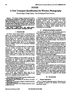
M-1 Y(n) = bm .X(n – m) …………(1) m=0 Here M represents the length of FIR filter, bm are the filter coefficients, X(n – m) denotes the data samples at time (n – m) and Y(n) represents output data. The filter coefficients can be calculated using “fda tool” (filter design and analysis tool) of Matlab. The direct implementation of Eq.(1) is called as the unfolded direct form. The architecture of UDF FIR Filter is shown in Fig.1. x(n)
b0
X b0
D
b1
x(n-1)
X
D
D b2
+
X
b(M-2)
+
x(n-M+2)
X
+
D
b(M-1)
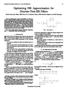
It is obvious that a large number of multipliers & adders to the extent of filter order are required in UDF scheme. In case of FDF implementation, number of multipliers is reduced to half. However, the same may be implemented sequentially by using single multiplier and pre-adder as explained in the next sections. 3. Proposed Architecture of FIR Filtering IP Core 3.1 UDF FIR IP Core The design methodology of UDF FIR Filter IP core is discussed here. The basic data flow diagram of UDF FIR core is given in Fig.3.
x(n-M+1)
X
+
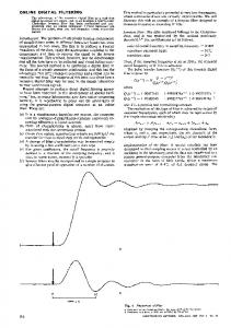
Y(n) Fig.1 The UDF FIR Filter architecture 2.2 Folded Direct Form (FDF) Every linear phase FIR filter has symmetrical coefficients around the middle one. The symmetrically located coefficients can be added before multiplication. So the amount of multiplication required to calculate an output sample can be reduced to half by using Folded Direct Form architecture. For FDF filter, Eq.(1) can be written in the following form. Y(n) = b0 (X(n) + X(n – (M-1)) + b1(X(n-1) + X(n – (M-2)) + …. (2) The structure for mapping of Eq.(2) on hardware is shown in Fig.2. For this folded architecture pre-adder is required to add the symmetrically located data sample value and then multiplied with the respective coefficients. Similarly the 2nd data sample value and 2nd last data value are added on single clock and multiplied with respective coefficient value and so on.
Y(n)
Fig.2 The FDF FIR Structure
Fig.3 UDF FIR Filter Data Flow diagram From Fig.3, the main component is control logic that is implemented in the form of a controller. In addition to a controller block, two memory blocks, a data path (mac unit, multiplier, and adder) and a rounding unit are used. Two input and one output registers are also used. These modules are parameterized and programmable. They can be changed dynamically and can be reused. The word length for coefficients and data can be changed to any value (4bits, 8 bits, 16 bits etc). The type of filter (low pass, high pass, band pass, band stop) can be changed and number of taps (coefficients) of the filter is programmable. The following specifications were considered to design the IP Core. No. of Coefficients = from 2 to 128 Word length of data & coefficients = from 4 to 16 No. of mac units = 1 Data RAM size = 16 x 128 Coefficient RAM size = 16 x 128 The filter coefficients were obtained from “fda tool” of Matlab. A controller was designed using Verilog HDL. The coefficients were loaded in Coefficient RAM with the load signal high. This signal was kept high for a number of cycles depending on the length of filter. When load signal goes low, it resets all modules except the coefficient RAM. The block diagram and internal architecture of the Controller is shown in Fig.4.
Proceedings of the Third International Conference on Information Technology: New Generations (ITNG'06) 0-7695-2497-4/06 $20.00 © 2006
IEEE
Pointer_update_block_seg
Write_addr_gen_seg
Counter_conv read_addr_gen_seg 127 to 0 Write_update Input_cnt Reset_n
Write_addr 7bits
clock
Output_count
Reset_n
7 bits
clock read_addr Ram_enable_seg
127 to 0 Output_ram_en Write_addr out_enable_seg Output_ram_en 127 to 0
Output_en
Output_en
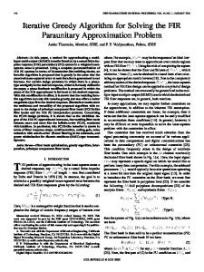
Fig.4 Internal Architecture of Controller The controller is designed to generate five output signals depending on the status of input signals. It consists of the following components. Counter_conv module Write_gen module Ram_addr module Ram_enable module Out_enable module The counter_conv module is a simple down counter that will down count with each clock. It starts from the maximum number that is equal to length of the filter and down counts to zero, then goes back to maximum. The write_gen module is another down counter but the frequency of this module is 1/(length of filter) times the clock frequency. The ram_enable module generates enable signal for write operation in the ram. The ram_addr module is designed to generate read address for the ram. The out_enable module controls the output enable signal for the mac unit, rounding unit and out_reg unit. The single multiplier architecture for UDF FIR IP Core implementation is shown in Fig.5.
Fig.5 UDF FIR IP Core Architecture The sequence of operations is now explained. The input data and coefficients of the filter are taken one by one from two separate RAM’s by getting signal from the controller and are multiplied. The output of the multiplier goes to an adder where it is added to the previous product. The output of adder is supplied to mac unit and output of mac provides the output Y(n). All the components of this core are parameterized and programmable. They were implemented using Verilog hardware description language. 3.2 DFD FIR IP Core The basic data flow diagram of Folded Direct Form (FDF) FIR core is shown in Fig.6.
Proceedings of the Third International Conference on Information Technology: New Generations (ITNG'06) 0-7695-2497-4/06 $20.00 © 2006
IEEE
Fig.7 FDF FIR Filter RAM internal architecture 4. Simulation Results
Fig.6 Data Flow Diagram of FDF FIR Filter In this architecture small change in controller section is required. Here, two read addresses for data ram are generated in single clock cycle, to get two data sample values added before multiplication with the respective coefficient. Moreover small change for data ram is also required i.e two read address busses, two output data busses and one write address bus for writing the data on respective location. A pre-adder is required in this core to add the symmetrically located coefficients. The addressing scheme adopted for generation of read and write address is implemented using the circular buffer similar to unfolded direct form FIR core. The only difference regarding folded architecture is that two read addresses on single clock are generated for data ram. The coefficients ram address length also is half of unfolded direct form ram for same number of taps of filter. The modification in data ram for folded architecture is shown in Fig.7. For this ram two de-multiplexers are required. Two outputs according to the addresses generated by controller i.e data sample values location are available for addition and then multiplied with respective coefficients to get the output of the core.
The building blocks of the architecture shown in Fig.5 & Fig.6 were synthesized using Leonardo Spectrum. The filter coefficients were obtained using Matlab “fda tool”. The coefficients were converted to fixed point format for input to the core. The output results of the core were converted to floating point numbers by the Matlab. The proposed filter was also evaluated in the test bench. To verify the output of cores modelsim and matlab tools were used. The synthesis results of the UDF and FDF FIR cores for 8 bit and 16 bit word lengths are given in Table 1 and Table 2 respectively. Table 1:UDF FIR Core Synthesis Results. Description of Resources Used Slice register Flip Flop Latches 4 input lookup table IOB FF IOB Latches Total Equi gate count for design J. Tag gate count for IOB’s External GCLK IOB’s Max Freq
Proceedings of the Third International Conference on Information Technology: New Generations (ITNG'06) 0-7695-2497-4/06 $20.00 © 2006
IEEE
UDF, 16 Bit, 11 Tap
UDF, 8 Bit, 11 Tap
405 out of 1536 85 320 752 out of 1536 17 32 10040
213 out of 1536 53 160 329 out of 1536 9 16 4496
2736
1585
1 out of 4
1 out of 4
35.464 MHz
42.7 MHz
Table 2 FDF FIR Core Synthesis Results Description of Resources Used Slice register Flip Flop Latches 4 input lookup table IOB FF IOB Latches Total Equi gate count for design J. Tag gate count for IOB’s External GCLK IOB’s Max Freq
FDF, 16 Bit, 11 Tap
FDF, 8 Bit, 11 Tap
420 out 1536 132 288 913 out 1536 17 32 11476
228 out of 1536 84 144 421 out of 1536 9 16 5409
of
of
2688
1536
1 out of 4
1 out of 4
31.329 MHz
43.324 MHz
In case of folded architecture, the area requirement is larger as compared to unfolded direct form. It is due to the fact that two multiplexers are used in data ram and two address buses are required to generate two read addresses. The word length and number of taps of filter can be changed readily. From the results, it is clear that the Core is parameterized and programmable. 5. Conclusions Design methodology for UDF and FDF FIR Filtering IP Cores was presented. The basic architectures and data flow scheme was devised and implemented. The component modules were described in Verilog HDL. The synthesis results were obtained using LeoSpec. The results show that the proposed IP Core is parameterized and programmable. The parameterized cores are an essential component for IP based SoC design. The core can be optimized for different data and coefficient widths. The work will be extended to implement folded direct form using distributed arithmetic and reusable SoC design based on IP cores, will be explored further.
[4] Warren Savage, John Chilton and Raul Camposano: “IP Reuse in the System on a Chip Era”, IEEE Journal 2000. [5] Han Qi, Liang Yu and Wei Tong Li: “IP-Based SoC Design Methodology”, Proc. Of World Computer Conf., August 2000. [6] ZHAO Junchao, CHEN Weiliang and WEI Shaojun: “Parameterized IP Core Design”, No. 0-78036677-8/01, pp.744-747, 2001 IEEE [8] A.T.Erdogan, M. Hasan, and T.Arslan, “Algorithmic low power FIR cores”, IEE Proc. Circuits Devices Syst. Vol-150, No.3, June 2003. [9] C.H. Wang, A.T. Erdogan, and T. Arslan : “High Throughput and Low Power FIR Filtering IP Cores”, O-7803-8445-8/04 2004 IEEE. [10] Vijay Sundararajan, Keshab K.Parhi , “Synthesis of Low Power Folded Programmable Coefficient FIR Digital Filters”; IEEE, 2000. [11] Jongsun Park, Khurram Muhammad, and Kaushik Roy: “High-Performance FIR Filter Design based on sharing multiplication”, Trans. IEEE Trans. On Very Large Scale Integration (VLSI) Systems, Vol.11, No.2, pp.244-253, April 2003. [12] Zhangwen Tang, Jie Zhang and Hao Min, “A High Speed, Programmable, CSD Coefficient FIR Filter”; IEEE Transaction on Consumer Electronics, Vol.48, No.4, November 2002. [13] A.T.Erdogan, T.Arslan, “Low Power Implementation Of Linear Phase FIR Filters For Single Multiplier CMOS Based DSPs”; IEEE International Symposium on circuits and systems(ISCAS’98),1998 [14] A.T.Erdogan, E. Zwyssig, and T.Arslan, “Architectural trade-offs in the design of low power FIR filtering cores”, IEE Proc. Circuits Devices Syst. Vol.151, No.1, February 2004. [15] C.H. Wang, A.T. Erdogan, and T. Arslan : “Algorithmic Implementation of Low-Power High Performance FIR Filtering IP Cores”, Proc. 18th Int. Conference on VLSI Design (VLS2688ID’05), 10639667/05 2005 IEEE.
References [1] International Technology Roadmap for Semiconductors ITRS:2005, Semiconductor Industry Association, www.itrs.net. [2] Michael Keating and Pierre Bricaud, “Reuse Methodology Manual for System-on-a-Chip Designs”, Kluwer Academic Publishers, 1998. [3] Daniel D. Gajski, Allen C.-H. Wu, Viraphol Chaiyakul, Shojiro Mori, Tom Nukiyama and Pierre Bricaud, Essential Issues for IP Reuse, IEEE J., 2000.
Proceedings of the Third International Conference on Information Technology: New Generations (ITNG'06) 0-7695-2497-4/06 $20.00 © 2006
IEEE