This article has been accepted for publication in a future issue of this journal, but has not been fully edited. Content may change prior to final publication. Citation information: DOI 10.1109/ACCESS.2017.2776293, IEEE Access
1
A Framework for Hardware Efficient Reusable IP Core for Grayscale Image CODEC Anirban Sengupta, Senior Member IEEE, Dipanjan Roy, Student Member IEEE, Saraju Mohanty, Senior Member IEEE, Peter Corcoran, Fellow IEEE
Abstract— This paper proposes two major novelties: (a) mathematical framework for hardware resource efficient IP core based image compression and decompression (CODEC). The framework includes CODEC functions that are capable to determine the pixel intensities of a compressed gray scale image using significantly lesser hardware resources. Digital pixel values of original image is fed as an input to the functions of proposed IP framework and compressed digital pixel values of compressed image is generated. Similarly, digital pixel values of compressed image are fed into another functions of proposed framework for image decompression (b) the second novelty is using the derived IP functions to propose designs of reusable IP cores for complete Haar Wavelet Transformation (HWT) based lossy image CODEC. Testing of images from various datasets (NASA, medical applications etc.) in terms of hardware resources, image quality and compression efficiency have indicated that proposed IP core framework was successful in achieving hardware efficient CODEC compared to JPEG and conventional HWT CODECs. Index Terms— IP core, CODEC, hardware efficient, pixel intensity
I. INTRODUCTION
W
ITH the advancement of multi-media technologies and digital systems like digital camera, smart phone, scanner, tablets etc. high-resolution images can be captured easily [15, 19, 20]. Due to the better quality, these highresolution images occupy large storage space, take high transmission time and large bandwidth to upload/download an image [13] [14]. An efficient Intellectual Property (IP) block/ reusable core [11] [12] for image compression and decompression can compute (generate) the compressed image as well as reconstruct it through a single step computation each while preserving the compression efficiency and quality parameters of a captured image. Image compressions are of two types: a) lossless, where no data loss is occurred; b) lossy, where less relevant data are discarded. Cameras in medical imaging [6], satellite imaging, forensic imaging use lossless image compression [7] [8], while camera in smart phones, tables, digicam, scanner etc uses lossy image compression. In the year 2000 Joint Photographic Experts Group (JPEG) proposed Discrete Wavelet Transformation (DWT) based image compression technique [1] [2] [3]. Haar Wavelet Transformation (HWT) based image compression is one of the
This work is financially supported by Council of Scientific and Industrial Research under sanctioned grant no. 22/730/17/EMR-II. A. Sengupta (
[email protected]) and D. Roy are with Computer Science and Engineering at Indian Institute of Technology, Indore. SP Mohanty is with Computer Science and Engineering at University of North Texas, Denton, USA. Peter Corcoran is with Engineering & Informatics at NUI Galway.
efficient forms of DWT [9] based image compression technique [10]. HWT decomposes each signal into two components, one is called average (approximation) or trend and the other is known as difference (detail) or fluctuation. Wavelet based image compression for volumetric medical imaging is discussed in [4]. Both lossy and lossless image compression is performed through directional wavelet transforms, block-based intra-band prediction and arbitrary decomposition structures. A new algorithm is proposed in [5] to select a threshold value through statistical analysis. The proposed algorithm is capable to maximize the compression ratio while minimizing the redundancy. Further reduction of image details is also achieved through Huffman encoding. None of these aforementioned approaches propose any functions for dedicated HWT-based image compressing and decompressing hardware or presents the design flow of an IP core for image compression and decompression. Rest of the paper is organized as follows: Section II highlights the novelties of proposed approach, Section III introduces proposed novel framework for IP block based HWT lossless image compression; Section IV introduces proposed novel IP core based design process for HWT-based image compressor and decompressor. Section V presents the analysis and results while Section VI presents the conclusion. II. NOVEL CONTRIBUTIONS OF THIS PAPER a) Proposes multiple functions for IP block based HWT image compression and image reconstruction. The IP functions are capable to directly determine the pixel intensities of a compressed gray scale image and can be used as a 'back box' in image processing tools as library where uncompressed digital pixel values of original image is fed as input to the IP block (representing a set of functions) and compressed digital pixel values of compressed image is generated. Similarly, digital pixel values of compressed image are fed into another IP black box (representing a set of functions) for image reconstruction. b) Using the derived IP functions for both compression/decompression, to propose the system design of a dedicated reusable soft IP cores for complete HWT based image compression and image reconstruction. Both designs have been successfully tested on Intel Cyclone FPGA. The IP core designs can be used directly as a macro-block (CODEC) in SoCs or standalone ASICs. The reduction of designer effort obtained when applying proposed IP core based compression method compared to normal hardware based HWT and DCT/JPEG based compression is shown in Table I, Table II
2169-3536 (c) 2017 IEEE. Translations and content mining are permitted for academic research only. Personal use is also permitted, but republication/redistribution requires IEEE permission. See http://www.ieee.org/publications_standards/publications/rights/index.html for more information.
This article has been accepted for publication in a future issue of this journal, but has not been fully edited. Content may change prior to final publication. Citation information: DOI 10.1109/ACCESS.2017.2776293, IEEE Access
2 Table1.Reduction of designer effort obtained when applying proposed IP based method in HWT Hardware Image Compression Proposed IP core based hardware HWT based image CODEC Resources Resources required for IP required for IP core 2 based core 1 based Image Image compression decompression 4 ASU, 4 ASU, 2 4 Mul Adder, 2 Mul
HWT matrix multiplication hardware based image CODEC Resources required for Image compression
Resources required for Image decompression
512 Mul, 511 Adder
512 Mul, 511 Adder
Proposed IP core based hardware HWT based image CODEC Speed of Speed of computation computation of of IP core 1 IP core 2 for for image image compression decompression 4 pixels per 4 pixels per execution execution
HWT matrix multiplication hardware based image CODEC Speed of computation for image compression
Speed of computation for image decompression
1 pixel per execution
1 pixel per execution
Table2.Reduction of designer effort obtained when applying proposed IP based method in JPEG Hardware Image Compression Proposed IP core based hardware HWT based image CODEC Resources Resources required for IP required for IP core 1 based core 2 based Image Image compression decompression 4 ASU, 4 ASU, 2 4 Mul Adder, 2 Mul
JPEG/DCT matrix multiplication hardware based image CODEC Resources required for Image compression
Resources required for Image decompression
8 Mul, 7 Adder
8 Mul, 7 Adder
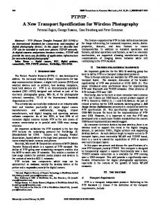
Further reduction in designer effort when applying proposed IP block based compression compared to normal software based HWT and DCT/JPEG based compression is shown in Fig. 1. The block diagram representation of proposed IP block/core based HWT image compression and decompression is shown in Fig.2. III. PROPOSED FRAMEWORK FOR IP BASED HWT LOSSY IMAGE COMPRESSION A. Problem Formulation For a gray scale input image of size NxN design an IP core for HWT-based image compression and decompression. B. Processing Input Image In the proposed approach, an NxN gray scale digital image with 8-bit depth is considered as input. An NxN matrix is generated by calculating the pixel intensity of each coordinate of the input image. Fig. 3 shows a generic 512x512 input image in the form of a matrix (A). The subscript and superscript of each element indicate the row number and column number of the element respectively. For example, the pixel intensity of 3rd row and 510th column of matrix ‘A’ is represented by element m3510. In a gray image, the pixel values lay between 0 and 255, where 255 indicates pure white and 0 indicates pure black. C. Background on Haar Wavelet Transformation In the process of Haar wavelet based transformation of input data two types of coefficient are generated: a) scaling coefficient and b) wavelet coefficient. Scaling coefficient represents the sum of two consecutive data samples and divided by two while wavelet coefficient represents the difference of two consecutive data samples and divided by two. Thus scaling coefficients represent the high-frequency signals known as coarse details of the data and wavelet coefficients represent the low-frequency signals known as finer details of the data. 2D-Haar wavelet transformation is comprised of: forward transformation of data and inverse transformation of data. Forward transformation is a two-step process i.e. level 1
Proposed IP core based hardware HWT based image CODEC Speed of Speed of computation computation of of IP core 1 IP core 2 for for image image compression decompression 4 pixels per 4 pixels per execution execution
JPEG/DCT matrix multiplication hardware based image CODEC Speed of computation for image compression
Speed of computation for image decompression
1 pixel per execution
1 pixel per execution
forward transformation on input data and level 2 forward transformation on level 1 transformed data. Similarly, inverse transformation is also a two-step process i.e. level 1 inverse transformation on compressed data and level 2 inverse transformation on level 1 decompressed data. D. Proposed IP Core Design for HWT-based Image Compression In the proposed IP core design for HWT-based image compression, we have introduced two functions to perform pixel intensity computation for level 1 forward transformation. The proposed functions transform the input image columnwise i.e. compute scaling coefficient by adding two vertically consecutive pixel intensities and divided by two for 1 to N/2th row, and compute wavelet coefficient by subtracting two vertically consecutive pixel intensities and divided by two for (N/2+1)th to Nth row. Thus divides the input image horizontally into two halves. The upper half represents the coarse details containing scaling coefficients (high frequencies) and the lower half represents the finer details containing wavelet coefficients (low frequencies). The proposed functions to perform pixel intensity computation for level 1 forward transformation are: 𝑝
𝑝
𝑝
𝑚2𝑛 +𝑚2𝑛−1
𝑋𝑛 = (
2 𝑝
𝑝
𝑋𝑁 2
+𝑖
=(
𝑚𝑁
)
(1) 𝑝
2 +𝑖−𝑗+1
−𝑚𝑁
2
2 +𝑖−𝑗
)
(2)
Where, N is the dimension of the square input image; n is the variable ranging from 1 to N/2, increases in every row; i is the variable ranging from 1 to N/2, increases in every row; p is the variable ranging from 1 to N, increases in every column; j is the variable ranging from N/2 to 1, decreases as ‘i’ increases. Eqn.1 is used for calculating 1 to N/2th row and Eqn.2 is used for calculating (N/2+1)th to Nth row of the input image. The corresponding level 1 forward transformation image in the form of matrix ‘X’ is shown in Fig.4 where calculation of pixel intensity is performed based on the aforementioned equations.
2169-3536 (c) 2017 IEEE. Translations and content mining are permitted for academic research only. Personal use is also permitted, but republication/redistribution requires IEEE permission. See http://www.ieee.org/publications_standards/publications/rights/index.html for more information.
This article has been accepted for publication in a future issue of this journal, but has not been fully edited. Content may change prior to final publication. Citation information: DOI 10.1109/ACCESS.2017.2776293, IEEE Access
Input Uncompressed digital pixel intensity of grey scale image ‘M’
Min (2X)
X Storing ‘W’
Writing code for generating ‘W’ matrix
X
X Storing (WT)-1
Generate (WT)-1
(a) Input Uncompressed digital pixel intensity of grey scale image ‘M’
Min (2X) Generating 8X8 ‘DCT’ matrix (D)
X Computing level 1 forward transformation (W * M)
X
X Generate WT
Storing the result (X) of level 1 forward transformation
X Storing ‘W’
Designer effort through conventional image HWT compression = 9X X X Computing level 1 X X Storing the result (L) inverse Generate Storing of level 1 inverse -1 transformation W W-1 transformation (WT)-1 * B+)
X Computing level 2 forward transformation B = (X * WT) ) X Computing level 2 inverse transformation (L * W-1) )
3 X Storing ‘B’
X Storing into ‘C’
Note: B+ is the image matrix after quantization and rounding Designer effort through conventional image HWT decompression = 8X Total designer effort for conventional lossy image HWT CODEC = min (17X) + 1X (Thresholding) = min (18X)
X Store ‘D’
X Extract 8X8 block of image pixel (M)
X Levelize ‘M’
X Computing level 1 DCTbased forward transformation (D * M)
X
X Generate DT
Storing the result (Y) of level 1 forward transformation
X Store ‘DT
X Computing level 2 DCT-based forward transformation N = (Y * DT)
X Storing ‘N’
Designer effort through conventional JPEG/DCT image compression = 11X X
X Storing ‘R’
Compute R = (Q50 * N+)
X Computing level 1 DCT-based inverse transformation P= (DT * R)
X Storing the result (P) of level 1 inverse transformation
X Computing level 2 DCT-based inverse transformation C= (P * D)
X Rounding ‘C’
X De-levelize ‘C’
X Storing ‘C’
Note: N+ is the image matrix after quantization and rounding Designer effort through conventional JPEG/DCT image decompression = 8X (b)
Total designer effort for lossy JPEG image CODEC = min (19X) + 2X (Quantization) + 1X (Rounding) = min (22X) Input
Uncompressed digital pixel intensity of grey scale image ‘M’
Min (2X) Write code for automatically feeding pixel values of ‘M’
X Compute on proposed IP block 1
X Storing ‘B’
Designer effort through proposed IP block based image HWT compression = 4X X Min (2X) Compute on X Write code for proposed IP Storing automatically feeding ‘C’ block 2 pixel values of ‘B+’ Note: B+ is the image matrix after Thresholding Designer effort through proposed IP block based image HWT decompression = 4X (c) Total designer effort for lossy image CODEC through proposed approach IP based HWT CODEC= min (8X) + 1X (Thresholding) = min (9X) (Thresholding) = 18X
Fig.1. Reduction of designer effort obtained when applying proposed IP based method in Software Image Compression (Reduction of 9X and 13X compared to conventional HWT image compression and JPEG/DCT image compression respectively)
We have also introduced two functions to perform pixel intensity computation for level 2 forward transformations on the level 1 transformed image. The proposed functions transform the level 1 transformed image row-wise i.e. compute scaling coefficient by adding two horizontally consecutive pixel intensities and divided by two for 1 to N/2th column, and compute wavelet coefficient by subtracting two horizontally consecutive pixel intensities and divided by two for (N/2+1)th to Nth column. Thus divides each half of level 1 transformed image into vertically two halves and finally divides the input image into four quarters. The upper-left quarter contains the scaling coefficients of scaling coefficient (high-high frequencies), the upper-right quarter contains the scaling coefficients of wavelet coefficient (high-low frequencies), the lower-left quarter contains the wavelet coefficients of scaling coefficient (low-high frequencies) and the lower-right quarter contains the wavelet coefficients of wavelet coefficient (low-low frequencies). The proposed functions to perform pixel intensity computation for level 2 forward transformations are:
𝑞
𝑝
𝑥𝑛 ±𝑥𝑛
𝐵=(
𝐵=(
2
)
𝑞 𝑝 𝑥𝑁 ±𝑥𝑁 +𝑖 2 2
2
(3)
)
(4)
Where, N is the dimension of the square level 1 transformed image; n is the variable ranging from 1 to N, increases in every row; i is the variable ranging from 1 to N/2, increases in every row; p is the odd variable ranging from 1 to N, increases in every column; q is the even variable ranging from 2 to N, increases in every column. The 1st and 2nd part of Eqn.3 is used for calculating upper-left and upper-right quarter of the level 1 transformed image respectively. The 1 st and 2nd part of Eqn.4 is used for calculating lower-left and lower-right quarter of the level 1 transformed image respectively. The corresponding level 2 forward transformation image in the form of matrix ‘B’ is shown in Fig.5 where calculation of pixel intensity is performed based on the aforementioned equations. The HWT-based compressed image matrix (B) can
2169-3536 (c) 2017 IEEE. Translations and content mining are permitted for academic research only. Personal use is also permitted, but republication/redistribution requires IEEE permission. See http://www.ieee.org/publications_standards/publications/rights/index.html for more information.
This article has been accepted for publication in a future issue of this journal, but has not been fully edited. Content may change prior to final publication. Citation information: DOI 10.1109/ACCESS.2017.2776293, IEEE Access
4
Fig. 2. Framework for IP based image compression and decompression through dedicated hardware
be generated in one step computation from the input image matrix (A) through the following proposed functions: 𝑞
𝑞
𝑚2𝑛 +𝑚2𝑛−1
𝐵 = ((
2 𝑞
𝑞
𝑚2𝑛 +𝑚2𝑛−1
𝐵 = ((
2 𝑞
2
+𝑖−𝑗+1
𝑞
𝐵 = ((
2
2 𝑝
𝑝
𝑚2𝑛 +𝑚2𝑛−1
)−(
−𝑚𝑁
2
2
)+(
𝑞
+𝑖−𝑗+1
−𝑚𝑁
2
2
) /2)
(5)
) /2)
(6)
𝑝
+𝑖−𝑗
2
𝑚𝑁
𝑝
𝑞
𝑚𝑁
𝐵 = ((
𝑝
𝑚2𝑛 +𝑚2𝑛−1
)+(
𝑚𝑁 2
𝑝
+𝑖−𝑗+1
)−(
2
+𝑖−𝑗
2 𝑝
+𝑖−𝑗
−𝑚𝑁
𝑚𝑁 2
) /2) (7)
𝑝
+𝑖−𝑗+1
−𝑚𝑁 2
+𝑖−𝑗
2
) /2) (8)
Where, variable N, n, i, p, q are defined earlier; j is the variable ranging from N/2 to 1, decreases as ‘i’ increases. Eqn. 5 and 6 is calculated from Eqn. 3 and Eqn. 7and 8 is calculated from Eqn. 4 with the help of Eqn. 1 and 2. To generate the compressed image matrix ‘B’, Eqn. 5 is used for calculating intensity of pixels corresponding to both row
Fig. 3. Generic pixel value of fa 512x512 image
and column index 1 to N/2; Eqn. 6 is used for calculating intensity of pixels corresponding to row index 1 to N/2 and column index > than N/2 to N; Eqn. 7 is used for calculating intensity of pixels corresponding to row index > than N/2 to N and column index 1 to N/2; Eqn. 8 is used for calculating intensity of pixels corresponding to both row and column index > than N/2 to N. Those aforementioned functions can be used as a dedicated macro block in any image processing toolbox software like Matlab, OpenCV directly to perform HWT-based image compression. E. Compression and Decompression of Image Data Thresholding is performed on the compressed image pixel (matrix) ‘B’ using function ‘f’, where ‘f’ is defined as follows: 𝑝 𝐵, 𝑏𝑛 > 𝑇 𝐵′ = 𝑓(𝐵, 𝑇) = { (9) 𝑝 0, 𝑏𝑛 ≤ 𝑇 Where, B’ are the compressed image pixels after applying threshold based on the aforementioned function and ‘T’ is the
Fig. 4. Forward HWT-based level 1 transformed image matrix
2169-3536 (c) 2017 IEEE. Translations and content mining are permitted for academic research only. Personal use is also permitted, but republication/redistribution requires IEEE permission. See http://www.ieee.org/publications_standards/publications/rights/index.html for more information.
This article has been accepted for publication in a future issue of this journal, but has not been fully edited. Content may change prior to final publication. Citation information: DOI 10.1109/ACCESS.2017.2776293, IEEE Access
5 hard threshold value. The compressed image matrix B’ is then converted from a 2D matrix to a 1D array through zigzag scanning. Thereafter the 1D array is encoded through Huffman encoding in order to generate the bit stream data of the compressed image to store it in a storage device. To decompress the image from the stored data, the stored bit stream data is decoded through Huffman decoding and then the compressed image matrix B’ is reconstructed through inverse zigzag scanning. F. Proposed IP Core Design for HWT-based Image Decompression (Image reconstruction) HWT-based image decompression can be achieved in two different ways. One way is, combining upper-left with lower left quarter together as well as upper-right with lower-right quarter together. This divides the level 1 decompressed image vertically into two halves (left half and right half), subsequently then combining left half and right half together thus generating the final decompressed image. Second way is, combining upper-left with upper-right quarter together and lower-left with lower-right quarter together. This divides the level 1 decompressed image horizontally into two halves (upper half and lower half), subsequently then combining upper half and lower half together thus generating the final decompressed image. In the proposed IP core design for HWT-based image decompression, we have introduced two functions for each of the cases to perform pixel computation for level 1 inverse transformation and two functions for each of the cases to perform pixel computation for level 2 inverse transformations. For the first case, the proposed functions for level 1 inverse transformation transforms the compressed image column-wise i.e. subtract ith and (N/2+i)th row’s pixel intensity for odd rows, and add ith and (N/2+i)th row’s pixel intensity for even rows. Thus level 1 HWT-based inverse transformation represents the level 1 decompressed image into two halves. The left half represents the coarse details containing scaling coefficients (high frequencies) and the right half represents the finer details containing wavelet coefficients (low frequencies). The proposed functions for level 2 inverse transformation transforms the level 1 transformed image rowwise i.e. subtract ith and (N/2+i)th column’s pixel intensity for odd columns, and add ith and (N/2+i)th column’s pixel intensity for even columns. Thus level 2 HWT-based inverse
Fig. 5. Forward HWT-based level 2 transformed image matrix
transformations construct the complete decompressed image. For the next case, the proposed functions for level 1 inverse transformation transforms the compressed image row-wise i.e. subtract ith and (N/2+i)th column’s pixel intensity for odd columns, and add ith and (N/2+i)th column’s pixel intensity for even columns. Thus level 1 HWT-based inverse transformation represents the decompressed image into two halves. The upper half represents the coarse details containing scaling coefficients (high frequencies) and the lower half represents the finer details containing wavelet coefficients (low frequencies). The proposed functions for level 2 inverse transformation transforms the level 1 transformed image column-wise i.e. subtract ith and (N/2+i)th row’s pixel intensity for odd rows, and add ith and (N/2+i)th row’s pixel intensity for even rows. Thus level 2 HWT-based inverse transformations construct the complete decompressed image. The proposed functions to perform first type of pixel intensity computation for level 1 inverse transformation are:
𝐿 = (𝑏′𝑥𝑧 − 𝑏′𝑁𝑧
)
(10)
𝐿 = (𝑏′𝑥𝑧 + 𝑏′𝑁𝑧
)
(11)
2
2
+𝑥 +𝑥
Where, N is the dimension of the square compressed image matrix; z is the variable ranging from 1 to N, increases in every column; x is the variable ranging from 1 to N/2, increases in every alternate row. Eqn.10 is used for calculating the pixel value of odd rows and Eqn.11 is used for calculating the pixel value of even rows of the compressed image. The corresponding level 1 decompressed image in the form of matrix ‘L’ is shown in Fig.6 where calculation of each pixel is performed based on the aforementioned equations. The proposed functions to perform first type of pixel intensity computation for level 2 inverse transformations are:
𝐶=
(𝑙𝑥𝑧
𝑁 +𝑧 2
− 𝑙𝑥
𝑁 +𝑧 2
𝐶 = (𝑙𝑥𝑧 + 𝑙𝑥
)
(12)
)
(13)
Where, N is the dimension of the square level 1 decompressed image matrix; z is the variable ranging from 1 to N/2, increases in every alternate column; x is the variable ranging from 1 to N, increases in every row. Eqn.12 is used for calculating the pixel value of odd columns and Eqn.13 is used for calculating the pixel value of even columns of the level 1 decompressed image. The corresponding level 2
Fig. 6. Inverse HWT-based level 1 transformed image matrix
2169-3536 (c) 2017 IEEE. Translations and content mining are permitted for academic research only. Personal use is also permitted, but republication/redistribution requires IEEE permission. See http://www.ieee.org/publications_standards/publications/rights/index.html for more information.
This article has been accepted for publication in a future issue of this journal, but has not been fully edited. Content may change prior to final publication. Citation information: DOI 10.1109/ACCESS.2017.2776293, IEEE Access
6 decompressed image in the form of matrix ‘C’ is shown in Fig.7 where calculation of each pixel is performed based on the aforementioned equations. The proposed functions to perform next type of pixel intensity computation for level 1 inverse transformation are: 𝑁
𝐿 = (𝑏′𝑥𝑧 − 𝑏′𝑥2
𝑁
𝐿 = (𝑏′𝑥𝑧 + 𝑏′𝑥2
+𝑧
+𝑧
)
(14)
)
(15)
Where, N is the dimension of the square compressed image matrix; z is the variable ranging from 1 to N, increases in every column; x is the variable ranging from 1 to N/2, increases in every alternate row. Eqn.14 is used for calculating the pixel value of odd rows and Eqn.15 is used for calculating the pixel value of even rows of the compressed image. The corresponding level 1 decompressed image in the form of matrix ‘L’ is shown in Fig.6 where calculation of each pixel is performed based on the aforementioned equations. The proposed functions to perform next type of pixel intensity computation for level 2 inverse transformations are:
𝐶 = (𝑙𝑥𝑧 − 𝑙𝑁𝑧
+𝑥
𝐶 = (𝑙𝑥𝑧 + 𝑙𝑁𝑧
+𝑥
2
2
)
(16)
)
(17)
Where, N is the dimension of the square level 1 decompressed image matrix; z is the variable ranging from 1 to N, increases in every column; x is the variable ranging from 1 to N/2, increases in every alternate row. Eqn.16 and Eqn. 17 are used for calculating the pixel value of odd rows and even rows of the level 1 decompressed image. The HWT final decompressed image pixel intensities (of matrix C) can be generated in one step computation from compressed image matrix (B’) through following proposed functions: 𝑁
𝑁
C = (𝑏′𝑖 − 𝑏′𝑁 ) − (𝑏′𝑖2
− 𝑏′𝑁2
𝑔
𝑔 2
+𝑔
+𝑖
2
𝑁
𝑁
C = (𝑏′𝑖 − 𝑏′𝑁 ) + (𝑏′𝑖2
− 𝑏′𝑁2
𝑔
𝑔 2
+𝑔
+𝑖
𝑁
𝑁
+ 𝑏′𝑁2
𝑔
𝑔 2
+𝑔
+𝑖
2
+𝑔 +𝑖
𝑁
𝑁
+ 𝑏′𝑁2
𝑔 2
+𝑖
+𝑔
2
(19)
)
(20)
+𝑔 +𝑖
A. IP Core Design for HWT-based Image Compression To design an IP core for HWT-based image compression a Data Flow Graph (DFG) for HWT-based image compression is designed based on the Eqn. 5 – Eqn.8 shown in Fig. 8 (a). The DFG is then scheduled based on designer specified resources e.g. four 32-bit adder-subtractor unit (ASU) and four 32-bit multipliers, shown in Fig. 8(b) (Note: four 32-bit ASU 0and four 32-bit Mul are chosen as device support for I/O pins beyond this are not available with Cyclone II FPGA. Further, 32 –bit resources have been selected because each resource operates on floating point value during computation which requires 32 bit IEEE single precision format in normalized scientific notation). The green nodes represent ASU and the blue nodes represent multiplier in the graph. The multiplexing scheme is performed on the scheduled DFG based on the resource constraints. Multiplexing scheme is the process of representing each resource with corresponding inputs and outputs. For example in Fig 8(b), operation 1 and operation 5 are computed through same functional unit i.e. ASU1. Similarly, opn 2 & opn 6; opn 3 & opn 7; opn 4 & opn 8 are computed through ASU2, ASU3, and ASU4 respectively. The datapath processor of the complete IP core is designed based on the multiplexing scheme of each system resource. Multiplexer and demultiplexer can be integrated easily into the datapath based on the multiplexing scheme. The control unit controls different components of the datapath and makes synchronization between them. It is responsible for activating and deactivating signals like selector, deselector, latch strobe,
) (18)
)
+𝑖
C = (𝑏′𝑖 + 𝑏′𝑁 ) + (𝑏′𝑖2
𝑔
+𝑖
+𝑔
2
C = (𝑏′𝑖 + 𝑏′𝑁 ) − (𝑏′𝑖2
+𝑔
IV. DESIGN OF IP CORE FOR HWT-BASED IMAGE COMPRESSOR AND DECOMPRESSOR
)
(21)
Fig. 7. Inverse HWT-based level 2 transformed image matrix
Where, N is the dimension of the square input image matrix; g is the variable ranging from 1 to N/2, increases in every alternate column; i is the variable ranging from 1 to N/2, increases in every alternate row. To reconstruct the each pixel value of matrix ‘C’ Eqn.18 is used for odd row and odd column elements, Eqn.19 is used for odd row and even column elements, Eqn.20 is used for even row and odd column elements, Eqn.21 is used for even row and even column elements of matrix B’. (a) (b) Fig. 8(a) DFG of HWT-based image compression, (b) Scheduled DFG based on 4 adder-subtractor unit and 4 multiplier
2169-3536 (c) 2017 IEEE. Translations and content mining are permitted for academic research only. Personal use is also permitted, but republication/redistribution requires IEEE permission. See http://www.ieee.org/publications_standards/publications/rights/index.html for more information.
This article has been accepted for publication in a future issue of this journal, but has not been fully edited. Content may change prior to final publication. Citation information: DOI 10.1109/ACCESS.2017.2776293, IEEE Access
7
Q1CI
Q2CI
Q3CI
Q4CI
Q2CI
Q1CI Q4CI
Q3CI
Q1CI=pixels computed row wise of compressed image (CI) as per Eqn. 5 Q2CI=pixels computed row wise of compressed image (CI) as per Eqn. 6 Q3CI=pixels computed row wise of compressed image (CI) as per Eqn. 7 Q4CI=pixels computed row wise of compressed image (CI) as per Eqn. 8
Fig.9. IP core for HWT-based image compressor system The four output of the IP core are computed for four quarters and increases row-wise in each quarter of compressed image (CI))
enabler etc. in the datapath processor so that the components like multiplexer, demultiplexer, latch, functional unit (adder, multiplier etc.), register etc. response at the right time. Our proposed IP core design for HWT-based image compression system is shown in Fig.9 where the left block is the controller and the right block represents the datapath processor of the complete IP core design of HWT-based image compressor system. Each component of datapath processor and the control unit of HWT-based image compressor are designed using VHDL as the hardware description language. The IP core is capable to accept the 8-bit digital pixel value (Note: we have considered 8-bit as it provides the maximum grayscale shades) of a grayscale input image, perform level 1 and level 2 forward transformations and generate the digital pixel value of the corresponding compressed image. For example, as shown in Fig. 8, m11, m21, m12, m22 is taken as inputs which represents the pixel intensities of input image as shown in Fig. 3 and generates the outputs as b11, b1257, b2571, b257257 which represents the pixel intensities of compressed image as shown in Fig. 5. Similarly, the remaining pixel intensities of the compressed image are determined. The internal schematic block diagram representation of datapath processor is shown in Fig. 10. This novel IP core of HWT-based image compressor system can be used as a black box reusable core in a camera SoC where a designer does not need to know internal process of HWT image compression. B. IP Core Design for HWT-based Image Decompression To design an IP core for HWT-based image decompression a DFG is designed again based on the Eqn. 18 – Eqn.21 shown in Fig. 11(a). The DFG is then scheduled based on four 32-bit
ASU, two 32-bit adders and two 32-bit substractors, shown in Fig. 11(b). (Note: four 32-bit ASU, two 32-bit adders and two 32-bit subtractors are chosen because device support for I/O pins beyond this is not available with Cyclone II FPGA. Further, 32 –bit resources have been selected because each resource operates on floating point value during computation which requires 32 bit IEEE single precision format in normalized scientific notation).The green nodes represent ASU, the purple node represents subtractor and the pink nodes represent adder in the graph. In our proposed hardware design for HWT-based image decompression shown in Fig.12 where, the left block is the control unit and the right block represents the datapath processor of the complete hardware design of HWT-based image decompressor system. Each component of datapath and the control unit of HWT-based image decompressor are designed using VHDL as the hardware
(a)
(b)
Fig 11(a) DFG of HWT-based image decompression, (b) Scheduled DFG based on 4 adder-subtractor unit, 2 adder and 2 subtractor
2169-3536 (c) 2017 IEEE. Translations and content mining are permitted for academic research only. Personal use is also permitted, but republication/redistribution requires IEEE permission. See http://www.ieee.org/publications_standards/publications/rights/index.html for more information.
This article has been accepted for publication in a future issue of this journal, but has not been fully edited. Content may change prior to final publication. Citation information: DOI 10.1109/ACCESS.2017.2776293, IEEE Access
8
Fig10. Schematic system of datapath processor of HWT-based image compressor (computing two pixels in parallel)
Fig.12. System of IP core for HWT-based image decompressor (Note: The four output of the IP core are computed row-wise of decompressed image)
description language. The hardware is capable to accept the pixel value of a compressed image, perform level 1 and level 2
Fig.13. Internal System of datapath processor for HWT-based image decompressor
inverse transformations and generate the pixel value of the corresponding decompressed image. For example, as shown in
2169-3536 (c) 2017 IEEE. Translations and content mining are permitted for academic research only. Personal use is also permitted, but republication/redistribution requires IEEE permission. See http://www.ieee.org/publications_standards/publications/rights/index.html for more information.
This article has been accepted for publication in a future issue of this journal, but has not been fully edited. Content may change prior to final publication. Citation information: DOI 10.1109/ACCESS.2017.2776293, IEEE Access
9
Fig.14. Simulation of IP core 1: 2D Image compressor (for test image shown in Fig.2). Note: q1 = b11, q2 =b1257, q3 =b2571, q4 =b257257 of compressed image
Fig.15. Simulation of IP core 2: 2D Image decompressor (for test image shown in Fig.2). Note: OUT1 = c11, OUT1 =c12, OUT1 =c13, OUT1 =c14 of decompressed image TABLE III COMPARISON OF DEVICE UTILIZATION FOR PROPOSED IP CORES, NORMAL HWT AND JPEG CODEC Total logic Total register Total pins IP Core elements 4360 583 433 Proposed Forward HWT 5329 391 384 Proposed Inverse HWT > 33216 >34593 Normal Forward HWT >33216 >34593 Normal Inverse HWT 12121 1826 322 Standard JPEG CODEC TABLE IV FOR IP BASED HWT COMPRESSED IMAGE FOR T=25 Original Compresse Compression Images MSE size (bits) d size (bits) efficiency (%) Image 1 2097152 653383 68.84 86.2 Image 2 2097152 540771 74.21 174 Image 3 3276800 812689 75.20 102 Image 4 3276800 1001555 69.44 148 Image 5 3276800 989390 69.81 61.4 Image 6 2097152 459841 78.07 239
Images Image 1 Image 2 Image 3 Image 4 Image 5 Image 6
TABLE V FOR JPEG/DCT COMPRESSED IMAGE Compress Original Compression ed size MSE size (bits) efficiency (%) (bits) 2097152 710608 66.12 35.81 2097152 743664 64.54 38.93 3276800 1133296 65.41 49.9 3276800 1733456 47.1 77.3 3276800 1304352 60.19 35.41 2097152 942320 55.07 96.17
PSNR 28.78 25.72 28.03 26.44 30.25 24.34
PSNR 32.59 32.77 31.15 29.25 32.64 28.3
Fig. 11, b11, b1257, b2571, b257257 is taken as inputs which represents the pixel intensity of compressed image as shown in Fig. 5 and generates the outputs as c11, c12 or c21, c22
(depending on the enabler of ASU) which represents the pixel intensity of decompressed image as shown in Fig. 7. The complete datapath processor shown is Fig. 12 is implemented in two sub-block diagram as shown in Fig. 13 and the detailed schematic representation of each block of Fig. 13 is shown in Fig. 14. This novel hardware of HWT-based image decompressor can be used as a black box for a user who has no knowledge about the internal process of HWT-based image decompression. Both IP cores are ready to simulate in a synthesis tool and can be emulated in any FPGA (Field Programmable Gate Array) device. The hardware design of both the IPs is implemented in Altera Quartus II 7.2. The simulation result and the device utilization summary are discussed in the next section. V. RESULTS AND ANALYSIS CT images [16], NASA images [17] and standard 512x512 gray scale test images [18] are used as image dataset to verify and compare the proposed framework and IP core designs for HWT-based image compression & decompression with normal HWT-based IP core and JPEG/DCT IP core. As mentioned earlier all the aforementioned IP cores are implemented in Altera Cyclone II family, device no. EP2C35F672C6. Table III reports the comparison between proposed HWT-based CODEC , normal HWT-based IP core and standard JPEG/DCT IP core in terms of total used logic elements , registers, and I/O pin. As shown in Table III our proposed HWT-based IP core uses less resources whereas the normal HWT-based IP core can not be implemented in our used device due to lack of I/O pins. The simulation result for IP core 1 and 2 is shown in Fig. 14 and 15 respectively which
2169-3536 (c) 2017 IEEE. Translations and content mining are permitted for academic research only. Personal use is also permitted, but republication/redistribution requires IEEE permission. See http://www.ieee.org/publications_standards/publications/rights/index.html for more information.
This article has been accepted for publication in a future issue of this journal, but has not been fully edited. Content may change prior to final publication. Citation information: DOI 10.1109/ACCESS.2017.2776293, IEEE Access
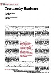
10 compared to standard JPEG/DCT method. The graphical comparison of compression efficiency, PSNR and MSE is also shown in Fig. 16, 17 and 18 respectively. VI. CONCLUSION AND FUTURE WORK
Image datasets
Fig16 Comparison of compression efficiency (%) for proposed vs. standard JPEG/DCT based compression
In this paper, a novel IP design based HWT image compression and decompression including its mathematical framework is proposed. The models can be used as a dedicated macro block in the library of an image processing toolbox to perform end to end HWT-based image compression. Further, the designed hardware can be used as an IP core in digital camera systems to perform image compression and decompression. Our future works aims to develop IP based video CODEC through mathematical functions, followed by subsequent validation in commercial synthesis tool. REFERENCES [1] [2] [3] [4]
Image datasets
Fig27 Comparison of PSNR for proposed vs. standard JPEG/DCT based compression
[5] [6]
[7] [8]
[9]
Image datasets
[10]
Fig38 Comparison of MSE for proposed vs. standard JPEG/DCT based compression
[11]
indicates that the designed IP core/IP block framework was successful in compression and decompression of test image (shown in Fig.2) . Similarly, successful results were obtained for all tested images selected from 3 datasets [16]-[18]. Total six images are selected from 3 datasets [16]-[18] to report the compression efficiency for different threshold (T) values. Additionally, the Mean Square Error (MSE) [1,2] and the Peak Signal to Noise Ratio (PSNR) [1,2] of the compressed images is also reported. Table IV reports the comparison between the original image and the proposed IP based compressed image for hard threshold T=25 in terms of storage size in bits. Further, it also reports the compression efficiency percentage, MSE and PSNR of all the test images. Table V reports the same quality parameters of the standard JPEG/DCT based compressed image. It can be observed that the compressed image generated through proposed HWTbased IP core achieves higher compression efficiency
[12] [13]
[14]
[15] [16] [17] [18]
[19]
S. Benchikh and M. Corinthios, “A hybrid image compression technique based on DWT and DCT transforms,” International Conference on Advanced Infocom Technology 2011, China, 2011, pp. 1-8. A. M. G. Hnesh and H. Demirel, “DWT-DCT-SVD based hybrid lossy image compression technique,” International Image Processing, Applications and Systems (IPAS), Hammamet, 2016, pp. 1-5. ISO/IEC 15444-1 | ITU-T Rec. T.800, Information Technology - JPEG 2000 Image Coding System: Core Coding System, 2002. T. Bruylants, A. Munteanu, and P. Schelkens,”Wavelet based volumetric medical image compression”, Signal Processing: Image Communication, vol 31, 2015, Pages 112-133. A. A. Nashat and N. M. H. Hassan, "Image compression based upon Wavelet Transform and a statistical threshold," International Conference on Optoelectronics and Image Processing, Warsaw, 2016, pp. 20-24. A. Bilgin and M. W. Marcellin, “Applications of reversible integer wavelet transforms to lossless compression of medical image volumes,” Proceedings. 1998 IEEE International Symposium on Information Theory (Cat. No.98CH36252), Cambridge, MA, 1998, pp. 411. S. Li, H. Yin, X. Fang and H. Lu, “Lossless image compression algorithm and hardware architecture for bandwidth reduction of external memory,” in IET Image Processing, vol. 11, no. 6, 6 2017, pp. 379-388. G. Scarmana and K. McDougall, “Exploring the application of some common raster scanning paths on lossless compression of elevation images,” 2015 IEEE International Geoscience and Remote Sensing Symposium (IGARSS), Milan, 2015, pp. 4514-4517. R. K. Lama, S. Shin, M. Kang, G. R. Kwon and M. R. Choi, "Interpolation using wavelet transform and discrete cosine transform for high resolution display," 2016 IEEE International Conference on Consumer Electronics (ICCE), Las Vegas, NV, 2016, pp. 184-186. C. Yu and S.J. Chen, "Design of an efficient VLSI architecture for 2-D discrete wavelet transforms," in IEEE Transactions on Consumer Electronics, vol. 45, no. 1, pp. 135-140, Feb 1999. A. Sengupta, "Evolution of the IP Design Process in the Semiconductor/EDA Industry [Hardware Matters]," in IEEE Consumer Electronics Magazine, vol. 5, no. 2, pp. 123-126, April 2016. A. Sengupta, "Cognizance on Intellectual Property: A High-Level Perspective," in IEEE Consumer Electronics Magazine, vol. 5, no. 3, pp. 126-128, July 2016. P. M. Corcoran, P. Bigioi and E. Steinberg, "Wireless transfer of images from a digital camera to the Internet via a standard GSM mobile phone," ICCE. International Conference on Consumer Electronics (IEEE Cat. No.01CH37182), Los Angeles, CA, 2001, pp. 274-275. P. M. Corcoran, P. Bigioi and E. Steinberg, "Wireless transfer of images from a digital camera to the Internet via a standard GSM mobile phone," in IEEE Transactions on Consumer Electronics, vol. 47, no. 3, pp. 542547, Aug 2001. I. Andorko, P. Corcoran and P. Bigioi, "A dual image processing pipeline camera with CE applications," IEEE International Conference on Consumer Electronics (ICCE), Las Vegas, 2011, pp. 737-738. Public Lung Database to Address Drug Response, Available. http://www.via.cornell.edu/databases/crpf.html. NASA Image and Video Library, [Online]. Available. https://images.nasa.gov/#/ Dataset of Standard 512x512 Grayscale Test Images [Online]. Available. http://decsai.ugr.es/cvg/CG/base.htm, Last Accessed on 18 Aug 2017. E. Kougianos, S. P. Mohanty, G. Coelho, U. Albalawi, and P. Sundaravadivel, “Design of a High-Performance System for Secure
2169-3536 (c) 2017 IEEE. Translations and content mining are permitted for academic research only. Personal use is also permitted, but republication/redistribution requires IEEE permission. See http://www.ieee.org/publications_standards/publications/rights/index.html for more information.
This article has been accepted for publication in a future issue of this journal, but has not been fully edited. Content may change prior to final publication. Citation information: DOI 10.1109/ACCESS.2017.2776293, IEEE Access
11 Image Communication in the Internet of Things (Invited Paper)”, IEEE Access Journal, Volume 4, 2016, pp. 1222--1242. [20] S. P. Mohanty, “A Secure Digital Camera Architecture for Integrated Real-Time Digital Rights Management”, Elsevier Journal of Systems Architecture, Volume 55, Issues 10-12, December 2009, pp. 468-480.
Peter Corcoran is a Fellow of IEEE, the Founding Editor of IEEE Consumer Electronics Magazine and holds a Personal Chair in Electronic Engineering at the College of Engineering & Informatics at NUI Galway. He is co-author on 300 technical publications and coinventor on 300 granted US patents.
Anirban Sengupta (M’09-SM’17) is Assistant Professor (Associate Professor appointment approved) in Computer Science and Engineering at Indian Institute of Technology Indore. He has been an active researcher with strong publications in the emerging areas of ‘Hardware Security’, ‘IP Core Protection’, ‘Privacy and Digital Rights Management for Electronics Devices’, ‘Forensic Engineering for Security’. He has been awarded prestigious IEEE Distinguished Lecturer (Renowned DL of IEEE CE Society) by IEEE Consumer Electronics Society in 2017. His research achievements have received wide media coverage as IET International News , United Kingdom in December 2017 issue of IET Member News periodical (Vol.9, Issue 46, pp.5). He has been awarded "Outstanding Associate Editor" Award from IEEE TCVLSI Letter Editorial Board, IEEE Computer Society in Sep 2017. He has been inducted into the Executive Committee of IEEE Computer Society Technical Committee on VLSI in Oct 2017. He is recipient of 'Sir Visvesvaraya Faculty Research Fellow' by Ministry of Electronics & IT. He has 133 Publications & Patents with bulk of them in IEEE and IET. He is currently Editor-in-Chief of IEEE VLSI Circuits & Systems Letter of IEEE Computer Society Technical Committee on VLSI. He also currently serves in several Editorial positions as Senior Editor, Associate Editor, Editor and Guest Editor of several IEEE Transactions/Journals, IET and Elsevier Journals including IEEE Transactions on Aerospace and Electronic Systems (TAES), IEEE Transactions on VLSI Systems, IEEE Access Journal, IET Journal on Computer & Digital Techniques, Elsevier Microelectronics Journal, IEEE Consumer Electronics Magazine, IEEE VLSI Circuits & Systems Letter. He further serves as Guest Editor of IEEE Transactions on VLSI Systems, IET Computers and Digital Techniques and IEEE Access Journals. He is the Technical Program Chair of 36th IEEE International Conference on Consumer Electronics (ICCE) 2018 in Las Vegas, 15th IEEE International Conference on Information Technology (ICIT) 2016, 3rd IEEE International Symposium on Nanoelectronic and Information Systems (iNIS) 2017 and 2019 IEEE International Symposium on VLSI (ISVLSI) in Florida. Several of his IEEE publications have appeared in 'Top 50 Most Popular Articles' from IEEE Periodicals. His Patents have been cited in various industry patents such as IBM Corporation, Siemens, Qualcomm and STC University of Mexico. He has supervised around 15 candidates including several Ph.D. candidates all of whom are/were placed in academia and industry. He has successfully commissioned special issues on ‘Hardware Security, Privacy, IP protection’ in IEEE TVLSI, IET CDT, IEEE Access as well as IEEE CEM which have received wonderful response from scientific community. Further due to high quality special issue in IEEE Access Journal in 2016, He has also been conferred award from IEEE Access for his outstanding contribution. He is also recipient of ‘Best Research Paper Award 2017’ by Indian Institute of Technology Indore. He has been awarded highest rating ‘Excellent’ by expert committee of Department of Science & Technology (DST) based on the performance (output) in externally funded project in 2017. His research ideas have been awarded competitive funding by various prestigious agencies such as Department of Science & Technology (DST), Council of Scientific and Industrial Research (CSIR) and Department of Electronics & IT (DEITY). More information available at: www.anirbansengupta.com Dipanjan Roy (S’16) is a research scholar in Computer Science and Engineering at Indian Institute of Technology (I.I.T) Indore. He worked as a software development engineer in “Amazon Development Center, Bangalore. Saraju P. Mohanty (S’00-M’04-SM’08) is a Professor at the Department of Computer Science and Engineering, University of North Texas, where he directs the NanoSystem Design Laboratory. He is author of 220 publications. He currently serves on the editorial board of IEEE Transactions on Computer-Aided Design of Integrated Circuits and Systems (TCAD and many others. He is currently the Editor-in-Chief of IEEE Consumer Electronics Magazine.
2169-3536 (c) 2017 IEEE. Translations and content mining are permitted for academic research only. Personal use is also permitted, but republication/redistribution requires IEEE permission. See http://www.ieee.org/publications_standards/publications/rights/index.html for more information.