1114
IEEE TRANSACTIONS ON CIRCUITS AND SYSTEMS—I: REGULAR PAPERS, VOL. 51, NO. 6, JUNE 2004
Reusable Silicon IP Cores for Discrete Wavelet Transform Applications Shahid Masud, Member, IEEE, and John V. McCanny, Fellow, IEEE
Abstract—Architectures and methods for the rapid design of silicon cores for implementing discrete wavelet transforms over a wide range of specifications are described. These architectures are efficient, modular, scalable, and cover orthonormal and biorthogonal wavelet transform families. They offer efficient hardware utilization by exploiting a number of core wavelet filter properties and allow the creation of silicon designs that are highly parameterized, including in terms of wavelet type and wordlengths. Control circuitry is embedded within these systems allowing them to be cascaded for any desired level of decomposition without any interface glue logic. The time to produce chip designs for a specific wavelet application is typically less than a day and these are comparable in area and performance to handcrafted designs. They are also portable across a wide range of silicon foundries and suitable for field programmable gate array and programmable logic data implementation. The approach described has also been extended to wavelet packet transforms. Index Terms—Biorthogonal, digital signal processing (DSP), discrete wavelet transforms (DWTs), field programmable gate array (FPGA), folding, image processing, IP cores, rapid design, silicon IP cores, system-on-chip architectures, very large-scale integration (VLSI) architecture, VHDL, video compression.
I. INTRODUCTION
T
HE USE OF wavelet transforms has become increasingly popular in a wide range of speech and image processing applications. However, the computational requirements of many wavelet systems, particularly image and video based systems are often best suited to a dedicated hardware implementation. To date, quite a number of investigations have been undertaken into both architectures for and specific implementations of silicon wavelet systems. Important contributions include the works of Parhi and Nishitani [1], Vishwanath and Owens [2], Chakrabarti et al. [3], Grzeszczak et al. [4] and Yu et al. [5]. These papers present a variety of schemes ranging from digit-serial architectures, filter-bank folding, lattice structures, systolic arrays, and other parallel processing schemes. An important feature of wavelet-based transforms is that there is an extremely large choice of possible wavelet basis functions that can be used for signal transformation. These are broadly categorized into two main families depending on Manuscript received August 1, 2003. This work was performed at Queen’s University, Belfast, U.K. This paper was recommended by Associate Editor Y. Wang. S. Masud is with the Department of Computer Science, Lahore University of Management Sciences, Lahore 54792, Pakistan (e-mail:
[email protected]). J. V. McCanny is with the DSiP Laboratories, School of Electrical Engineering, Queen’s University, Belfast BT9 5AH, U.K. (e-mail: j.mccanny@ ee.qub.ac.uk). Digital Object Identifier 10.1109/TCSI.2004.829236
whether the mother wavelet used satisfies conditions of “orthnormality” or “biorthogonality” [6], [7]. The level of wavelet decomposition performed varies widely and is algorithm dependent. In addition, the wavelet basis functions used at different levels of signal decomposition can themselves vary, as can related parameters such as lengths of filter banks, signal and filter coefficient wordlengths [8]. To date, most of the research which has been undertaken on wavelet architectures or designs has been focused on specific orthonormal wavelet systems such as Haar and Daubechies wavelets [4], [9], [10], with little work having been published on biorthogonal systems. The purpose of this paper is to present the results of research which has addressed this problem in a much more general sense. In particular, the paper describes generic and modular architectures that allow the rapid silicon design of a very broad range of wavelet systems directly from a high-level specification. This work has been motivated by two main considerations. The first is described above—the need to be able to create wavelet systems with a very wide range of specifications and tuned to different computational requirements. The second has been motivated by the challenges arising from the new era of system-on-a-chip (SoC), in particular, the desire to rapidly create complex and efficient reusable intellectual property cores. This extends our previous research in this area, which has shown how digital signal processing (DSP) systems-on-silicon can be created in a fraction of time previously thought possible using hierarchical libraries of generic DSP architecture templates captured in the form of a hardware description language [11]. The paper is structured as follows. Sections II and III introduce new generic architectures for the creation of orthonormal and biorthogonal wavelet filters, respectively. Details are then presented (Section IV) as to how these have been used for in creation of parameterized generators for the design of silicon wavelet cores. Section V then presents the result of numerous case studies covering both application specified integrated circuit (ASIC) and field programmable gate array (FPGA) implementation. As will be discussed, this approach allows wavelet designs to be created very rapidly from a high level specification. The designs produced are highly portable across different silicon foundries and can also easily be implemented in FPGA and programmable logic data (PLD) technology. This section also considers the implementation of wavelet packet transforms—systems that comprise both orthonormal and biorthogonal wavelet types and arbitrary filter bank connections. A generic method for folding wavelet architectures is also described. This allows hardware requirements to be tailored to computational bandwidth. The general conclusions from the work are then presented in Section VI.
1057-7122/04$20.00 © 2004 IEEE
MASUD AND McCANNY: REUSABLE SILICON IP CORES
1115
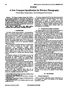
Fig. 1. Three-level DWT.
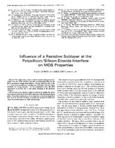
Fig. 2.
Two-level wavelet packet decomposition system.
II. GENERIC ARCHITECTURE FOR ORTHONORMAL WAVELET TRANSFORMS The hardware implementation of discrete wavelet transforms (DWTs) and wavelet packet transforms is based on the filter bank representation shown in Figs. 1 and 2, respectively. The implementation becomes complex because of a varying choice of wavelet, sample rate and the cumulative wordlengths at every stage. All these issues represent important challenges in the creation of efficient, generic and reusable architectures for the rapid design of wavelet systems. The system which has been created for implementing orthonormal wavelet filters exploits the fact that the polyphase (bi-phase in the case of wavelets) decomposition of wavelet filof ters can be obtained by writing the transfer function both the low- and high-pass filters in the form (1) where the symbols in this equation have their usual meaning.
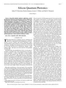
Equation (1) is, in effect, two filters that individually operate at half-rate on alternative data samples. This is followed by a decimation stage in wavelet decomposition, meaning that the function of each filter pair can be time multiplexed onto a single half-length filter, thus reducing filter hardware requirements by 50%. This is illustrated in top and bottom halves of Fig. 3, which shows how each multiplier block can be shared and used to compute alternate multiplications with even and odd order coefficients. In this approach data is input at the same rate as a full-length direct-form filter, but with alternative even and odd coefficients used in each processing cycle. The result is only output when both the even and odd index samples have been processed. The odd index samples computations are therefore temporarily stored in a buffer and are added to even sample computations to generate a complete filtered and decimated output. As will be noted, this system also offers the attraction that the data delay line is shared between the two filter structures and this is also beneficial in reducing hardware requirements. A transposed-direct-form filter in this situation would require two sep-
1116
Fig. 3. Time interleaved implementation of an
IEEE TRANSACTIONS ON CIRCUITS AND SYSTEMS—I: REGULAR PAPERS, VOL. 51, NO. 6, JUNE 2004
N -tap wavelet analysis filterbank.
arate delay lines with increased wordlengths. Since the filters used in wavelet transform have only a few taps, the use of direct-form filter structure poses no problems. The operation of the time-interleaved circuit can be explained through an eight-tap example as follows. The first sample arto find the first coefficient set , rives at time , respectively, available at each of the multipliers. The and is calculated and passed to the output. output value to encounter the The second (odd) sample arrives at time , and . The previous input coefficient values moves forward through one delay and hence it is not operated is calculated by any multiplier. The output value sample and this is stored in the buffer memory. When has moved to the next multiplier. The output value arrives, is then produced and added to the value that was calculated in the previous odd cycle. This represents the second decimated output value. The process continues and gives a decimated and filtered output. This approach is different from what has previously been described in that it is the function of each half- rate multiplier which is multiplexed onto the same piece of hardware and not the functions of the high and low pass filter as described in [11]. This is highly advantageous in terms of modularity (and thus, chip-design synthesis) and exploits the fact that both half-rate filters require the same filter lengths and data/coefficient wordlengths. As will be discussed, this approach is consistent with what we have adopted for biorthogonal wavelets (see Section III), where the high-pass/low-pass filter approach is not attractive due to filter order and wordlength variations. Another important difference is that the architecture in Fig. 3 does not require the computation of intermediate multiplications and additions that are then discarded because of decimation. This is highly advantageous in terms of power consumption. For the purpose of this paper, attention is focused mainly on high-throughput applications, and consequently, a bit-parallel,
word-serial filter implementation has been assumed. However, the basic architecture can be simply extended to create silicon generators in which other word formats, such as bit-serial or digit-serial data streams are used. This allows flexibility across applications in trading silicon area with performance and power consumption. III. GENERIC ARCHITECTURE FOR BIORTHOGONAL WAVELET FILTERS Biorthogonal wavelet filters evolved from the idea of having an exact reconstruction scheme in which the synthesis filters were different from the analysis filters. Hence the “orthonormality” condition is relaxed to “biorthogonality.” Such filters are attractive in that integer coefficients are possible and that they offer linear phase response [7]. However, because of this property the low-pass and high-pass filters in a biorthogonal filter bank can have different lengths with their filter coefficients possessing a combination of symmetry or anti-symmetry. The filter orders can also be even or odd. The linear phase property of the biorthogonal filters results in the coefficients being symmetric, in the case of odd order systems, or asymmetric in the case of even order systems. The coefficients can thus be written as (2) where is the filter order. Architectures for such linear phase filters can exploit this property to reduce the number of multo (even order) and to (odd tipliers from order). As before, downsampling by a factor of two allows alternate samples produced by the two analysis filters to be ignored. As in the case of orthonormal wavelet filters, polyphase decomposition can be applied so that only one output needs to be computed for every two input samples.
MASUD AND McCANNY: REUSABLE SILICON IP CORES
1117
TABLE I SEQUENCE OF OUTPUT FROM A NINE-TAP BIORTHOGONAL ANALYSIS FILTER
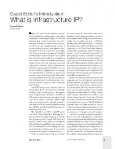
An efficient and generic architecture for biorthogonal wavelets has been derived by combining such properties and is described by first considering the example of an odd order (symmetrical filter coefficients) filter structure. Here a nine-tap filter is presented for illustration. The operation of this system can be described by considering the outputs produced by such a system as documented in Table I. From this, the following will be noted. • Coefficient symmetry simplifies the actual computations required thereby reducing the number of multiplications and additions needed. • Polyphase decomposition can be used to interleave even and odd order coefficient values to the same multiplier (as described in orthonormal case). • A multiplexing scheme can be devised to appropriately connect the delay line taps to the multiplier/accumulators at correct time instance in order to produce correct output values. The architecture developed from the above considerations is shown in Fig. 4. This is suitable for nine-tap wavelet filter pairs such as biorthogonal 9, 3 tap or biorthogonal 9, 7 tap systems. The entries in Table I under “Required output” provide the basis for this simplification. Since intermediate filter outputs at time are not required, we can spread the computations required at time etc., over two computation clock can be discycles. For example, the computations at time take tributed such that take place in even input cycle and
place in the odd input data cycle. A similar explanation holds for all the subsequent outputs. The results from the even cycle are stored in the output accumulator and added with results from the odd cycle to produce the final decimated output. A corresponding architecture for even-order biorthogonal wavelet filters possessing antisymmetry (i.e., ) can similarly be developed by replacing adders in Fig. 4 with subtractors. An example of a system (for a four, 4–tap filter pair) is also shown in Fig. 5. Even- and odd-order biorthogonal wavelet filters require different interconnections strategies for delay line taps and multiplier coefficients. The provision for this has been provided using the parameterization scheme described later so that the architecture is fully scalable for any type of biorthogonal wavelet filter. The number of multipliers required for each of the architectures described (and thus an estimate of the silicon area requirement) can be obtained from Number of multipliers
Filter Taps
(3)
where the operation requires rounding up of the value within the brackets to the nearest integer. Here, one adder is associated with the input of every multiplier. Similarly, adders are required in the accumulation path of the multiplier outputs. A further adder, with associated delay elements, is also required at the filter output for the accumulator (Figs. 4 and 5). Equivalent direct-form finite impulse remultipliers and adders for an sponse (FIR) filters require
1118
IEEE TRANSACTIONS ON CIRCUITS AND SYSTEMS—I: REGULAR PAPERS, VOL. 51, NO. 6, JUNE 2004
Fig. 4.
Nine-tap low-pass analysis filter for biorthogonal wavelet transform.
Fig. 5.
Efficient implementation of a four-tap biorthogonal wavelet filter.
-tap filter. Exploitation of symmetry reduces this number to multipliers and M adders. The polyphase decomposition technique, as presented in orthonormal wavelet filters, multipliers and adders for a similar requires implementation. The new architectures presented here, based on simultaneous exploitation of symmetry and polyphase decomposition, results in a saving of up to 4X over direct-form FIR filters and up to 2X over polyphase decomposition techniques, while retaining the modularity and scalability in the design. IV. RAPID DESIGN OF WAVELET TRANSFORM CORES Parameterized silicon cores to implement a wide range of orthonormal and biorthogonal wavelet functions have
been created using the generic architectures described. The core elements in these have themselves been created from a lower level library of parameterized architectural templates [Intellectual Property (IP) cores] for implementing functions such as multipliers, multiplexers and delay elements [11], with these captured using (VHDL). For the purpose of this research, attention was focused mainly on the use of bit parallel Booth encoded, Wallace-tree multipliers, although, as indicated earlier, the concepts are easily extendible to many other types of multipliers including ones with bit serial, digit serial as well as bit parallel data organizations. When coupled with parameterized wordlengths, levels of pipelining and filter length, this provides high flexibility in design space exploration and
MASUD AND McCANNY: REUSABLE SILICON IP CORES
1119
Fig. 6. Scalable architecture for biorthogonal wavelet filters.
allows the rapid tailoring of circuits to meet throughput, power and area requirements. Generic cores based on the blocks described, therefore, allow a multistage wavelet transform core for any orthonormal or biorthogonal wavelet type and at any wordlength (within practical bounds) to be quickly created and implemented as silicon designs. A. Orthonormal Wavelet Cores The orthonormal wavelet filter architecture in Fig. 3 was implemented using a number of modular building blocks. Here, the input component (i) comprises two multipliers in the filter bank and a delay element. The latter is incorporated to synchronise the input reading of data and thus facilitates the seamless interfacing of multiple wavelet blocks. The block labeled (ii) in Fig. 3 comprises two delay elements and two multiplier/accumulators (MACs) and implements repeating taps of the analysis filter bank. The output circuit for the analysis filter then comprises an accumulator and decimator as outlined in block (iii). In this case, outputs are only produced when two data samples have been processed. The delay element at the output removes the need of glue logic for cascading these cores. B. Biorthogonal Wavelet Cores The architectures for biorthogonal filters shown in Figs. 4 and 5 have been generalized into a scalable architecture, illustrated schematically in Fig. 6. This architecture was obtained by considering the fact that same filter coefficient will multiply with two different data samples due to symmetry and the coefficient supplied at input to each multiplier will change in even and odd cycles due to bi-phase decomposition. There is a small additional overhead incurred in this design in terms of adders and multiplexers but this makes the architecture much more generic and modular. Another important advantage of this scheme is that if offers a simple interconnection and scheduling mechanism that renders itself to architecture parameterization.
A parameterized SoC design system for implementing any general biorthogonal wavelet filter can be produced in the following four steps. The input parameters supplied to the core include number of taps, wordlengths and wavelet type. • Generation of delay line An -tap delay line is generated using latches. • Generation of processing elements The processing elements, each comprising a multiplier, an adder and two multiplexers are created. Every four taps of the filter requires one processing element (see Fig. 6). To facilitate the generation of architectures comprising biorthogonal wavelet filters with inverse-symmetry [i.e., ], the adder in the processing element of Fig. 6 is changed to a subtractor; examples include biorthogonal 6, 2 tap wavelet filters. This selection is also possible through generic parameters. • Generation of adder chain An adder chain is required to accumulate the results produced by the multiplications. The number of adders and their interconnections are also automatically generadders are required for this operation, ated. Here where is the number of processing elements. • Output decimator and accumulator The final constituent block in the scaleable architecture is the output accumulator based on a latch plus carry lookahead adder, as shown in Fig. 6. This produces a decimated output by storing the intermediate results in the latch. The output is controlled by a synchronous available signal. This removes the need for interface glue logic when creating multilevel wavelet systems. The generic circuits described for both orthonormal and biorthogonal wavelet filters operate using a simple control circuit, with the only external signals required being the Clock and Reset signals. Specific coefficient values are internally assigned during logic synthesis process and derived from generic specifications, as described below.
1120
IEEE TRANSACTIONS ON CIRCUITS AND SYSTEMS—I: REGULAR PAPERS, VOL. 51, NO. 6, JUNE 2004
C. Coefficient Allocation Procedure The architectures described have been captured in VHDL. This method allows replication of smaller processing blocks through generic specification but there is no direct mechanism to acquire the wavelet coefficients from a high level description. Coefficients cannot be directly supplied at time of instantiation because only “integers” are permitted as generic VHDL parameters. The following method was therefore developed to allow access to a wide range of wavelet families through a generic description. A MATLAB code was first used to generate a text file containing the coefficients for all required wavelets. The text file containing real number coefficients is converted to two’s-complement format at the maximum desired resolution of MAXbits. The variable MAX was chosen as 16 bits in this system. However, this can be easily varied. The actual coefficient resolution (between 1-bit and MAX-bits) is specified in the generic description of the cores during instantiation. These values are then appropriately embedded in a VHDL package that is included in the core description. Each wavelet filter is identified by a separate index value that is specified in generics and used to access the appropriate set of filter coefficients. The coefficient wordlengths are selected by a VHDL code that returns only the required number of bits of precision specified in the generics. The wordlength growth after every stage can easily be adjusted by observing the software simulation. V. DESIGN CASE STUDIES Numerous design examples have been undertaken to illustrate the ease and speed with which wavelet transforms can be implemented. The methods presented here allow a nonspecialist DSP engineer to develop a silicon implementation of a full wavelet system concurrently with algorithm development. The following generic parameters are all that need to be specified at the time of instantiation of any wavelet block: 1) wavelet type e.g., Daubechies, biorthogonal 9, 7 tap etc.; 2) levels of decomposition; 3) length of low-pass and high-pass filters in biorthogonal wavelets; 4) data wordlength; 5) coefficient wordlength; 6) wordlength extension to prevent overflow (and to cater for cascading stages). All the cores described below have been functionally tested and verified using VHDL test benches. It is important to note that the performance measures reported in this paper for each core are entirely dependent on chosen wordlengths and wavelet type. An important advantage of this approach is that it readily allows the choice of a particular core and corresponding wordlengths to be determined on the basis of given design constraints. The cores can be cascaded for a multiple level wavelet decomposition mirroring the signal flow graph. The control circuit of the cores designed here allows a direct cascading of multiple blocks for this purpose. For low-bandwidth systems, the data can be recycled for higher levels using appropriate memory, multiplexers, and control signals. A. Orthonormal Wavelet Transforms The following are some examples of silicon wavelet implementations developed using the methods described.
TABLE II CORE SPECIFICATIONS FOR DIFFERENT WORDLENGTHS OF BIORTHOGONAL 9, 7 TAP WAVELET FUNCTION
1) Daubechies wavelets: In this design, 9-bit data and coefficient values in two’s-complement format were used. The Synopsys environment was used to synthesize the design and generate a netlist file, which was then converted to a silicon layout. Such a core comprises about 12 K gates and requires an area of 0.39 mm . The performance measures are for single-stage decomposition implemented in a triple level metal, 0.18- m CMOS technology. This single stage filter bank can be reused to implement higher octaves by employing folding and scheduling techniques. A three-level cascaded wavelet decomposition based on a Daubechies four-tap wavelet, (as in Fig. 1), was instantiated, with coefficient and data resolution being 7 and 9 bits, respectively. A 6-bit truncation was applied after every stage so that the internal wordlengths are 18, 21, and 24 bits for the first, second, and third stages, respectively. In this case, the silicon area required is 0.625 mm requiring around 20 K gates. A clock frequency of over 160 MHz was achieved in this design. This corresponds to a data sample rate of 80 MSamples/s. 2) Symmlet 12-tap wavelet, two stages: In this case, a twolevel wavelet decomposition based on the use of two cascaded Symmlet 12-tap wavelet functions, was synthesized. Here the (two’s-complement) coefficient and data wordlengths were 10 and 9 bits, respectively, with internal wordlength accuracies of 25 and 32. Here, 9-bit truncation is employed between stages. This design requires 35 K gates and has a silicon area of 0.913 mm (0.768 mm 1.187 mm). B. Biorthogonal Wavelet Transforms A number of designs were also created based on biorthogonal wavelet filter architecture shown in Fig. 6. The details of each are presented below: 1) Biorthogonal 9, 7 tap wavelet transform: A typical silicon layout for a single stage design with two’s-complement 9-bit coefficients and data occupies an area of 0.321 mm in the ASIC technology used earlier and comprises around 10 K gates. It can process data at sample rates in excess of 150 MHz. Silicon designs for a wide range of wordlength specifications have also been created. Three single-stage cores along with storage memory can form a two-dimensional (2-D) wavelet decomposition as required in the JPEG 2000 image coding standard. Details of some of these cores are presented in Table II. The effect
MASUD AND McCANNY: REUSABLE SILICON IP CORES
1121
TABLE III FPGA IMPLEMENTATION OF BIORTHOGONAL WAVELET TRANSFORMS
of wordlengths specification on the size of the core is obvious from this table. The methods presented in this paper allow design changes and choices to be made on the fly. C. FPGA Implementation The biorthogonal wavelet filter designs were also ported to Xilinx 4052XL series speed grade FPGA devices. The performance figures obtained are tabulated in Table III, with details depending on the targeted device. This particular device was selected for the reasons of availability in the target library and the number of configurable logic blocks (CLBs) (1936) appeared sufficient for the demonstration of our architectures and designs. A clock frequency of over 65 MHz was achieved in all the implementations, which is sufficient for some real-time video processing applications. A similar design for a Daubechies eight-tap wavelet analysis using 8-bit data and 7-bit coefficients requires 353 CLBs and 50 input/output blocks (IOBs). D. Wavelet Packet Transform The cores developed previously for orthonormal and biorthogonal wavelet transforms have been employed to create silicon designs for a number of wavelet packet decomposition systems. Two related and important issues have to be addressed in the implementation of wavelet packet transforms. The first is that such systems allow different wavelet functions to be used to implement each filter bank. The second is interfacing of different filter banks at successive stages. The architectures described provide the means for doing this in a very straightforward manner. In the case of wavelet packet transforms, the internal architecture of the filter banks remains unchanged from the dyadic wavelet decomposition but the external arrangement for higher levels is variable and flexible. A basic core for wavelet decomposition can therefore be reused to produce any arbitrary wavelet packet decomposition. Such cores are easily cascadable because of the pipelined input and output and an embedded control circuit. The choice of a wavelet function and the interconnection of filter banks are easily specified during instantiation. Some examples of implementations based on this approach are given below. 1) Two-level wavelet packet transform: This design illustrates the use of wavelet transform cores in developing a two-
level wavelet packet decomposition, as shown in Fig. 2. The first level of has been instantiated with a Daubechies eight-tap wavelet core, whereas two Daubechies four-tap wavelet cores have been used in the second stage of analysis. As before, data and coefficient values are in a two’s-complement format and comprise 9 and 8 bits, respectively. The output from the first stage (Daubechies 8-tap) is truncated to 13 bits and used as input to the two subsequent filter banks. The output from the final (Daubechies four-tap) filter banks is then truncated to 15 bits. The methodology, however, allows a flexible mechanism for allocation and truncation of wordlengths. The resulting design requires 28 K gates and an area of 1.097 mm (0.806 mm 1.362 mm). The maximum input data throughput is in excess of 150 MHz. A similar wavelet packet transform with the wavelet functions reversed comprises 31 K gates but improves the power consumption by over 20%. This is due to the fact that the wavelet function with the higher number of taps is now at the second level of decomposition with this operating at half the frequency of the first. 2) Biorthogonal wavelet packets (Irregular Decomposition): A three-level wavelet packet transform has also been produced. A range of wavelet functions was utilized to demonstrate the flexibility in this scheme. The first stage uses biorthogonal 9, 7 tap wavelet filters, the second stage (i.e., two sets of filter banks) comprises biorthogonal 9, 3 tap wavelet functions and the third stage utilizes biorthogonal 6, 2 tap wavelet functions (two sets of filter banks). The last stage filter banks are connected to the low-pass output of stage 2. The high pass output of stage 2 is directly available at the output. The input data as well as the coefficient are represented in an 8-bit two’s-complement format. An 8-bit truncation was incorporated at the outputs of the first and the second stage filter banks. The design comprises 44 K gates. The characteristics of individual blocks are summarized in Table IV. As mentioned earlier, these cores easily operated at over 160 MHz corresponding to input data rate of 80 MSamples/s. 3) Combination of orthonormal and biorthogonal wavelets: In this case, a silicon layout for a two-level balanced wavelet packet tree, as shown in Fig. 2, was produced. Here, a biorthogonal 9, 3 tap wavelet function is employed in the first level, whereas the succeeding level comprises Daubechies four-tap and Daubechies eight-tap wavelet functions. The latter orthonormal filter banks are connected to the low-pass and the high-pass outputs of the first stage biorthogonal filter bank,
1122
IEEE TRANSACTIONS ON CIRCUITS AND SYSTEMS—I: REGULAR PAPERS, VOL. 51, NO. 6, JUNE 2004
TABLE IV SILICON AREA OF BLOCKS INSTANTIATED IN BIORTHOGONAL WAVELET PACKET DECOMPOSITION
Fig. 7. Folded implementation of an eight-tap wavelet filter.
respectively. The input data and coefficients comprised 9 bits with a similar truncation between the filter banks. The total silicon area in this case is 0.92 mm (0.735 mm 1.252 mm) and the number of gates required is 28 K. E. Architecture Folding1 The designs described contain separate hardware implementations for each stage in the filter bank. In many practical applications the 150-MHz sampling rate achievable from these cores is well beyond what is required. The architectures developed offer the attraction that these can be easily systematically folded and retimed through the multiplexing of operations (multiplication, addition, accumulation, etc.,) onto a reduced number of components. The amount of folding required depends on the wavelet choice and the downsampling (decimation) ratio. A parameterized generator for wavelet transforms that incorporates such folding has therefore also been developed, with the folding factor being incorporated as an additional parameter in generic specifications. The schematic of a Daubechies eight-tap wavelet filter instantiated with folding parameter of four is shown in Fig. 7. The principle of the folded wavelet cores is to spread the computations of wavelet coefficients over multiple computation cycles. The amount of time available depends upon the desired throughput, which is linked to the folding parameter. As 1The material provided in Section V-E and related information is subject of a U.S. patent application.
shown in the figure, the circuit computes the partial products , and . A for both the even and odd cycles at time similar core instantiated with folding parameter of two would consist of two multipliers each computing the partial products and , respectively. The accumulator at times in this circuit has been slightly modified to facilitate the operation over a variable range of folding requirements. In this case, the output block comprises two latches, in the forward and feedback paths, respectively, as well as a pipelined adder. Hardware sharing in this wavelet filter architecture leads to a tradeoff between speed, area, and power whilst retaining the generic architectural attributes and on-the-fly coefficient allocation described earlier. A provision has been made in the parameterization scheme to allow folding of the complete filter architecture on to a single multiplier. This means that an eight-tap Daubechies wavelet filter, instantiated with a folding parameter “4” comprises a single MAC unit onto which all the filtering operations are multiplexed. Further increases in hardware efficiency through multiplexing can be achieved by using digit-serial or bit-serial multipliers. However, the flexibility displayed in this scheme in terms of wordlength specification cannot be attained in other architectures. A silicon design capable of performing a three-level DWT and based on the use of the folded architecture described has been generated with details presented in Table V. The first stage operates at 160 MHz and has a folding parameter of “1.” The
MASUD AND McCANNY: REUSABLE SILICON IP CORES
1123
TABLE V SPECIFICATIONS OF THREE-LEVEL FOLDED WAVELET CORES
Fig. 8. Initial floor plan of a Daubechies eight-tap, three-level wavelet transform processor.
second stage operates at 80 MHz and has a folding parameter of “2.” Similarly, the third stage operates at 40 MHz with a folding parameter of “4.” The total number of gates required in this case, for a three-stage decomposition is around 36 K. The initial layout of this chip is shown in Fig. 8. VI. DISCUSSION AND CONCLUSION A methodology is presented that allows a nonspecialist to very rapidly design highly efficient silicon wavelet transform cores from a high level specification. This is based on generic scalable architectures utilising time-interleaved coefficients for the wavelet filters. These architectures are parameterized in terms of wavelet family, wavelet type, data wordlength and coefficient wordlength. The approach is flexible both in the scalability of architecture and the choice of wavelet basis functions. A new wavelet type can easily be added whenever required. The control circuitry required is self-contained and has been designed so that these can be cascaded without any interface glue logic, for any desired level of wavelet decomposition or reconstruction. Efficient architectures for both orthonormal and biorthogonal wavelet filters were developed and used as the basis for the parameterized generator presented. This contrasts with existing research, which has tended to focus mainly on
specific examples of orthonormal wavelets. Moreover, the new architectures for biorthogonal wavelet transforms reported are the first to concurrently exploit characteristic properties, such as symmetry and the multirate nature of such filters. Case studies for stand-alone and cascaded silicon cores for various wavelet algorithms, respectively, are reported. The typical design time to produce silicon layout of a wavelet-based system has been reduced to less than a day. The time from specification to implementation is the time required to run the simulation, synthesis, and layout tools. The designs have been captured in VHDL and are portable across a range of foundries, target technologies and are applicable to FPGA and PLD implementations. The use of a hierarchical approach used in the creation of the various silicon generators described means that tightly designed smaller blocks are used to create larger library blocks (such as multipliers) which are in turn used to create the circuits described. This “bottom-up,” architecture-based approach results in highly efficient silicon designs being created—comparable with handcrafted—and contrasts strongly with the common (and often highly inefficient) approach of creating RTL based cores from a high level VHDL description. As discussed in Section I, a number of specific DWT chip designs have been reported in the literature [4], [5], [11]–[16]. A key aspect of the generalized methodology described is that benchmark performance figures compare very favorably with previous, fixed specification, full-custom designs. For example, the Daubechies four-tap, 3-level 0.8- CMOS design reported by Yu et al. [5] requires a silicon area of 8.5 mm . This roughly corresponds to 0.679 mm in 0.18- CMOS technology and compares with a figure of 0.604 mm in our approach. Our design also produces much better area and performance figures than those reported by Sheu [12]. The FPGA results for the biorthogonal 9, 7 DWT also compare very favorably those reported by Altera [11], clearly demonstrating that it is possible to create generic silicon designs which are highly competitive with specific manual designs but can be created in a fraction of the time previously required. Whereas some FPGA implementations of biorthogonal wavelets have been reported [11]–[16], the full details of architecture and wordlengths are not available. Previously described implementations are based on direct-form FIR filter design and do not utilize the hardware efficiencies described. In addition, designs such as those reported by Schoner [13] and Truchetet [15] are specifically aimed at short-length wavelet filters with
1124
IEEE TRANSACTIONS ON CIRCUITS AND SYSTEMS—I: REGULAR PAPERS, VOL. 51, NO. 6, JUNE 2004
coefficients being “integers” or “powers of two.” The Altera FPGA megafunction [11] allows parameterization of input and output wordlengths but the wavelet choice is restricted. The designs presented in this paper are much more general any of the family of biorthogonal wavelet functions can be instantiated from the generic core described. A multilevel wavelet system can be produced using either a filter bank folding or by cascading a number of cores instantiated with appropriated wordlengths and wavelet choice. The former approach is hardware efficient but suffers from high latency, whereas the latter approach provides the highest throughput. Since a word-parallel data format was used in the design of the cores reported, the designs in the latter case may not be suitable for very high levels of decomposition or low throughput applications. In these circumstances, the folded cores presented in Section V and the use of digit-serial or bit-serial library components can improve silicon area efficiency while retaining the flexibility in wavelet choice and architecture scaling. This can provide efficient design solutions for a very broad range of target applications. Parameterized architectures for wavelet packet decomposition containing orthonormal and biorthogonal wavelet functions have also been created. The implementation examples described include arbitrary packet tree decomposition with a variety of wavelet combinations. An example containing a mix of orthonormal and biorthogonal wavelet functions has also been presented. The possibility of selectively applying quantization in any desired output path, as demonstrated, is advantageous in signal coding. In these applications, each subband contributes differently to the overall system characteristics and an independent assignment of wordlengths can make the hardware design much more flexible and efficient. This flexibility is not possible in previously presented architectures [16]. REFERENCES [1] K. K. Parhi and T. Nishitani, “VLSI architectures for discrete wavelet transforms,” IEEE Trans. VLSI Syst., pp. 191–202, June 1993. [2] M. Vishwanath, R. M. Owens, and M. J. Irwin, “VLSI architectures for the discrete wavelet transform,” IEEE Trans. Circuits Syst. II, vol. 42, pp. 305–316, May 1995. [3] C. Chakrabarti, M. Vishwanath, and R. M. Owens, “Architectures for wavelet transforms: A survey,” J. VLSI Signal Processing, pp. 171–192, 1996. [4] A. Grzeszczak, M. K. Mandal, S. Panchanathan, and T. Yeap, “VLSI implementation of discrete wavelet transform,” in IEEE Trans. VLSI Syst., Dec. 1996, pp. 421–433. [5] C. Yu, C. A. Hsieh, and S. J. Chen, “Design and implementation of a highly efficient VLSI architecture for discrete wavelet transform,” in Proc. IEEE Custom Integrated Circuits Conf., 1997, pp. 237–240. [6] I. Daubechies, “Orthonormal basis of compactly supported wavelets,” Commun. Pure App. Math., vol. XLI, pp. 909–996, 1988. [7] A. Cohen, I. Daubechies, and J. C. Feauveau, “Biorthogonal bases of compactly supported wavelets,” Commun. Pure Appl. Math., pp. 485–560, 1992. [8] S. Masud and J. V. McCanny, “Finding a suitable wavelet for imagecompression applications,” in Proc. IEEE Int. Conf. Acoustic Speech Signal Processing, vol. V, May 1998, pp. 2581–2584. [9] A. S. Lewis and G. Knowles, “VLSI architecture for 2-D Daubechies wavelet transform without multipliers,” Electron. Lett., pp. 171–173, 17, 1991. [10] T. C. Denk and K. K. Parhi, “VLSI architectures for lattice structure based orthonormal discrete wavelet transforms,” IEEE Trans. Circuits Syst. II, vol. 44, pp. 129–132, Feb. 1997.
[11] Biorthogonal wavelet filter megafunction (1997, Feb.). [Online]. Available: http://www.altera.com [12] M. H. Sheu, M. D. Shieh, and S. F. Cheng, “A unified VLSI architecture for decomposition and synthesis of discrete wavelet transform,” in Proc. IEEE Midwest Symp. Circuits Systems, vol. 1, Aug. 1996, pp. 113–116. [13] B. Schoner, C. Jons, and J. Villasenor, “Issues in wireless video coding using run-time-reconfigurable FPGAs,” in Proc. IEEE Symp. FPGAs for Custom Computing Machines, Apr. 1995, pp. 85–89. [14] F. Truchetet and A. Forys, “Implementation of still-image compressiondecompression scheme on FPGA circuits,” in Proc. IEEE Pacific Rim Conf. Communications, Computers Signal Processing, vol. 1, 1997, pp. 481–484. [15] ADV601 Chip, Analog Devices. [Online]. Available: http://www. analog.com [16] X. Wu, Y. Li, and H. Chen, “Programmable wavelet packet transform processor,” Electron. Lett., pp. 449–450, 18, 1999.
Shahid Masud (S’92–M’92) received the B.Sc.Engg. (Honors) from the University of Engineering and Technology, Lahore, Pakistan, the M.Eng.Sc. degree from the University of New South Wales, Sydney, Australia, and the Ph.D. degree from Queen’s University Belfast, Belfast, U.K., in 1990, 1992, and 1999, respectively. He was with Amphion Semiconductor Ltd., Belfast, U.K. He has published 20 papers in important journals and conferences and has three patents pending. He is currently an Assistant Professor at Lahore University of Management Sciences, Lahore, Pakistan. Dr. Masud is a member of the Institute of Electrical Engineers, U.K., and a Chartered Engineer (C.Eng.).
John V. McCanny (M’89–SM’95–F’99) received the B.S. degree (honors) in physics from the University of Manchester, Manchester, U.K., the Ph.D. degree in solid-state physics from the new University, Ulster, N. Ireland, U.K., and the higher doctorate (D.Sc.) degree (in recognition of his research contributions) from the Queen’s University Belfast, Belfast, U.K., in 1973, 1978, and 1998, respectively. He joined the Royal Signals and Radar Establishment (now Qinetiq), Malvern, U.K., in 1979, and was Principal Scientific Officer when he left in 1984. In 1984, he was appointed a Lecturer in the Department of Electrical and Electronics Engineering, Queen’s University Belfast, where he became a Reader in 1988 and a Full Professor in 1989. He is currently the Director of the Institute for Electronics Communications and Information Technology (ECIT), a $75 M facility currently being built on the Northern Ireland Science Park. He has published over 250 scientific papers and five research books in the field of very large-scale integrated architectures and system-on-chip design for signal and image processing, and holds ten patents. He has also successfully co-founded two high technology companies, Audio Processing Technology Ltd.—which markets hi-fi audio compression products worldwide, and Amphion Semiconductor—a leading supplier of semiconductor intellectual property for digital TV and video multimedia applications. Prof. McCanny was awarded a Royal Academy of Engineering Silver Medal for “outstanding contributions to U.K. Engineering leading to commercial development,” in 1996. He was also awarded an IEEE Third Millennium medal in 2000. From 1999–2000 he chaired the IEEE Signal Processing Society’s Technical Committee on the Design and Implementation of Signal Processing Systems and was also a member of the Society’s Technical Directions committee. He was elected Fellow of the Royal Society (of London) in 2002 and was also awarded a Commander of the Order of the British Empire (CBE) by Queen Elizabeth II in the same year. He has recently been awarded the 2003 Royal Dublin Society/Irish Times Boyle Medal, which recognizes scientific excellence in Ireland. He is a Fellow of the U.K. Royal Academy of Engineering, the Institute of Electrical Engineers, U.K., and the Institute of Physics, and a member of the Royal Irish Academy.