Furthermore, we demonstrate techniques for synthesizing the hardware and software units required to monitor the validity of ptLTL specifications. 1 Introduction.
Past Time LTL Runtime Verification for Microcontroller Binary Code Thomas Reinbacher1 , J¨org Brauer2 , Martin Horauer3 , Andreas Steininger1 , and Stefan Kowalewski2 1
Embedded Computing Systems Group, Vienna University of Technology, Austria 2 Embedded Software Laboratory, RWTH Aachen University, Germany 3 Department of Embedded Systems, UAS Technikum Wien, Austria
Abstract. This paper presents a method for runtime verification of microcontroller binary code based on past time linear temporal logic (ptLTL). We show how to implement a framework that, owing to a dedicated hardware unit, does not require code instrumentation, thus, allowing the program under scrutiny to remain unchanged. Furthermore, we demonstrate techniques for synthesizing the hardware and software units required to monitor the validity of ptLTL specifications.
1
Introduction
Program verification deals with the problem of proving that all possible executions of a program adhere to its specification. Considering the complexity of contemporary embedded software, this is a particularly challenging task. Conventional ad-hoc testing is significantly less ambitious; it is thus the predominant method in the (embedded) software industry. Typically, a set of test-cases is derived manually or automatically in a best effort fashion. Then, the arduous task of judging the results of a test-case run often remains with the test engineer. 1.1
Runtime Verification by Code Instrumentation
The field of runtime verification [7] has gained momentum as it links traditional formal verification and monitoring the execution of test cases. The aim is to increase confidence in correctness of the system, without claiming freedom from defects. In runtime verification, test oracles, which reflect the specification, are either automatically derived (e.g., from a given temporal logic formula that specifies a requirement) or formulated manually in some form of executable code. Correctness of an execution is then judged by means of evaluating sequences of events observed in an instrumented version of the program under scrutiny. Instrumentation can either be done manually, or automatically by scanning available program nodes (e.g., assignments, function calls, . . . ) at the level of the implementation language. Function calls are then inserted to emit relevant events to an observer, i.e., the test oracle. The latter approach has proven feasible for high-level implementation languages such as C, C++, and Java, as well as for hardware description languages such as VHDL and Verilog. Various runtime verification frameworks have thus emerged [6, 8, 13, 14, 20].
1.2
Pitfalls of Code Instrumentation
Despite considerable technical progress, existing approaches to runtime verification are not directly transferable to the domain of embedded systems software, mainly due to the following reasons: 1. Embedded code often adopts target-specific language extensions, direct hardware register and peripheral access, and embedded assembly code. When instrumenting such a code basis, one has to take all the particularities of the target system into account, depleting the prospect of a universal approach. 2. In its present shape runtime verification proves the correctness of high-level code. However, to show that a high-level specification is correctly reproduced by the executable program, it is necessary to verify the translation applied to the high-level code as it is not unknown for compilation to introduce errors [2, 9, 24]. One thus needs to prove that for a given source code P , if the compiler generates a binary code B without compilation errors, then B behaves like P [29]. Proving correctness of the compiler itself is typically not feasible due its complexity and its sheer size [21, 22]. Flaws introduced by the compiler may thus remain unrevealed by existing approaches. 3. Instrumentation at binary code level is never complete as long as the full control flow graph (CFG) is not reconstructed from the binary program. Although CFG reconstruction of machine code is an active research area [3, 12, 17], generating sound yet precise results remains a challenge. 4. Instrumentation increases memory consumption, which may be of economical relevance for small-sized embedded targets. We conclude that a non-instrumenting approach for microcontroller binary code may be a notable contribution to further establish the use of lightweight formal techniques, such as runtime verification, in the embedded software industry. 1.3
Requirements to Runtime Verification of Microcontroller Code
To overcome the pitfalls discussed so far, which prohibit the application of existing frameworks to the embedded systems domain, it is necessary to provide a framework that works on the level of binary code and additionally satisfies the following requirements: Req1: Generality For a verification on the binary code level the target microcontroller must be fixed. However, the approach shall not be bound to a certain compiler (version) or high-level programming language. Req2: No Code Instrumentation Typically, software event triggers are instrumented to report execution traces as sequences of observations. For small-scale embedded platforms, it is necessary to extract event sequences without code instrumentation. Req3: Provide Mechanics to Evaluate Atomic Propositions The atomic propositions (AP ) of the specification need to be evaluated on microcontroller states of the running system. We need to find a reasonable trade-off between expressiveness of the AP and the complexity of their evaluation.
Furthermore, to be useful in an industrial environment, some practical requirements need to be considered: Req4: Automated Observer Synthesis From a user point of view, it is desirable to input a specification in some (temporal) logic, which is automatically synthesized into an observer that represents the semantics of the temporal property. Req5: Usability We aim at a framework which is applicable in industrial software development processes; at best, this is a push-button solution. It shall be possible to include implementation-level variables in the specification, which are automatically mapped to the memory state on the target hardware. 1.4
Contributions to Runtime Verification
The contribution of this paper is a framework for supervising past time linear temporal logic (ptLTL) properties [15] in embedded binary code. ptLTL allows to specify typical requirements to embedded software in a straightforward fashion, which contrasts with our experiences using Computation Tree Logic (CTL) [31]. Further, we present a host application that interacts with a customized hardware monitoring unit and a microcontroller IP-core (executing the software under scrutiny), both of which are instantiated within an FPGA. In our approach, supervision of ptLTL specifications can take place either offline (using the host application) or online in parallel to program execution. Both options come along without any kind of code instrumentation or user-interaction. We implemented the presented approach into our testing framework called CevTes [30]. 1.5
Structure of the Paper
The presentation of our contributions is structured as follows. In Sect. 2, we present preliminaries used throughout the paper. Sect. 3 introduces our framework for runtime verification of binary code. We apply our approach to a real-life example in Sect. 4. We put our work in context with related work in Sect. 5 and conclude with a discussion of achievements in Sect. 6.
2
Preliminaries
This section introduces notations used in the remainder of the paper, including a formal microcontroller model and the finite-trace temporal logic ptLTL. 2.1
Formal Microcontroller Model
Addressing memory locations: Let Addr = {0 ≤ x < |Mem| : x ∈ N ∪ {0}} denote the set of memory locations of the microcontroller, where Mem represents the (linear) address space of the microcontroller memory. We write rx to address a specific memory location, e.g. , r20 denotes the memory location with address 20. We assume a memory mapped I/O architecture (e.g. Intel MCS-51), thus, I/O registers reside within Mem.
State of the microcontroller program: In the following, let Nk = {0, . . . , k− 1}. A state S of the microcontroller is a tuple hpc, mi ∈ Locs × (Addr → N2w ), where Locs is a finite set of program counter values, and m : Addr → N2w is a map from memory locations (with bit-width w) to memory configurations. The state space of the program is thus a subset of Locs × (Addr → N2w ). We denote the initial microcontroller state S0 by h0x00, m0 i where m0 represents the configuration of all memory locations after power-up and 0x00 is the assumed reset vector. State updates: State updates trigger a state transition, thereby, transforming a predecessor state S −1 into the current state S. A state update is a triple δ = hζδ , @δ , pc δ i, where ζδ is the new configuration of the altered memory location, @δ is its address, and pc δ is the new program counter value. Given a strict sequential execution of the program, state updates are in temporal order. A δ state update S −1 − → S transforms S −1 = hpc −1 , m−1 i into S = hpc δ , mi where: ( ζδ if i = @δ m(i) = −1 m (i) otherwise A sequence of events, denoted π, is a trace of state updates δ, e.g. , π = hδ0 . . . δn i. 2.2
Past Time LTL
While past time operators do no yield extended expressive power of future time LTL [10, Sect. 2.6], a specification including past time operators may sometimes be more natural to a test engineer [19, 23]. A ptLTL formula ψ is defined as ψ ::= true | f alse | AP | ¬ψ | ψ • ψ ψ | � ψ | � ψ | ψ Ss ψ | ψ Sw ψ where • ∈ {∧, ∨, →}. ψ means previously ψ, i.e., it is the past-time analogue of next. Likewise, the other temporal operators are defined as: �ψ expresses eventually in the past ψ and �ψ is referred to as always in the past. The duals of the until operator are Ss and Sw , i.e. , strong since and weak since, respectively. Monitoring operators: These basic operators can be augmented by a set of monitoring operators [15, 20]. The semantics of the monitoring operators is derived from the set of basic operators in ptLTL, thus, do not add any expressive power. However, they provide the test engineer a succinct representation of the most common properties emerging in practical approaches: ψ ::= ↑ ψ | ↓ ψ | [ψ, ψ)s | [ψ, ψ)w ↑ ψ stands for start ψ (i.e., ψ was false in the previous state and is true in the current state, equivalent to ψ ∧ ¬ ψ), ↓ ψ for end ψ (ψ was true in the
previous state and is false in the current state, equivalent to ¬ψ ∧ ψ), and [ψ1 , ψ2 ) for interval ψ1 ψ2 (ψ2 was never true since the last time ψ1 was true, including the state when ψ1 was true, equivalent to ¬ψ2 ∧ (( ¬ψ2 ) S ψ1 )). The set of atomic propositions AP contains statements over memory locations in Locs. Space constraints force us to refer the reader to [10, 15, 20] for a formal semantics. Determining satisfaction: It is important to appreciate that satisfaction of a ptLTL formula can be determined along the execution trace by evaluating only the current state S and the results from the predecessor state S −1 [15].
3
System Overview
HW Monitor
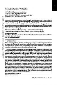
The following section details our runtime verification framework, as depicted in Fig. 1, which works on microcontroller binary code rather than a high-level representation of the program, thus meeting Req1.
State USB
updater
Synth. SW ptLTL observer
Binary *.hex
SUT (IP-Core)
Atomics checker
FPGA
Host Application
S
A
A
•
Synth. HW ptLTL observer
Atomics Atomics checkers checkers
Event logger δ0 . . . δn
A
•
A
A
A Data interface
A
I/O & Pheripherals
CPU
A
•
RAM PROM Program interface A A
A
Environment
Fig. 1. System overview
We address Req2 by a hardware monitor unit, which is transparently attached to an industrial microcontroller IP-core running on an FPGA. The monitor allows
to extract execution traces without code instrumentation. We tackle Req3 by a twofold approach: (i) Offline mode: We permanently send state updates δ from an hardware implemented event logger to a host application which applies δ to the current state S −1 to obtain the successor state S. The AP of the ptLTL formula ψ are evaluated on S and the validity of ψ is decided by a synthesized SW ptLTL observer. (ii) Online mode: As a self-contained alternative, we check the AP of the ptLTL formula on-the-fly and decide the validity of ψ by a synthesized HW ptLTL observer directly on the FPGA. We meet Req4 by instantiating an algorithm described by Havelund and Ro¸su [15], i.e., we generate observer for ptLTL as executable Java or VHDL code. Finally, we comply with Req5 by providing a graphical interface to the system and an optional debug file parser allowing to state formulas over high level symbols. 3.1
ptLTL Observer Synthesis
Runtime verification requires an observer to be attached to the system under test. Our approach supports a full FPGA based solution as well as a combined one where a hardware event logger stimulates a Java class on the host computer. Technically speaking, we derive (a) Java classes and (b) VHDL entities, both representing an observer for the specification ψ. In a subsequent step, (a) is compiled into executable Java code and (b) is synthesized into a netlist. Both observers rely on the hardware monitor unit to evaluate the AP of ψ. Whereas (a) utilizes event updates about the state of the microcontroller, (b) makes use of a dedicated atomics checker hardware unit. Observer synthesis thus consists of the following stages: (i) We use the ANTLR parser generator [26] to parse a ptLTL formula ψ, which yields an abstract syntax tree (AST) representing the specification. (ii) After some preprocessing of the AST, we determine the n subformulas ψ0 . . . ψn of ψ using a post-order traversal of the AST. (iii) We generate observers as executable Java or synthesizable VHDL code [15]. 3.2
Hardware Monitor Unit
The hardware monitor unit (cf. Fig. 1) is attached to the system under test, an (unmodified) off-the-shelf microcontroller IP-core1 , which is embedded into its application environment. The observer consists of three main components, namely an event logger, an atomics checker unit, and a synthesized ptLTL observer. The remainder of this section discusses the details of these components. Event logger The event logger wiretaps the data and the program interface of the microcontroller and collects memory updates δ non-intrusively. For example, if the currently fetched instruction is MOV [*20, 0x44], which moves the constant value 0x44 into r20 , and the current program counter pc equals 0xC1C1, then the event logger assembles a new state update δ = h0x44, 20, 0xC1C1i. 1
For our actual implementation we employ an Intel MCS-51 IP-core from Oregano Systems (http://www.oregano.at).
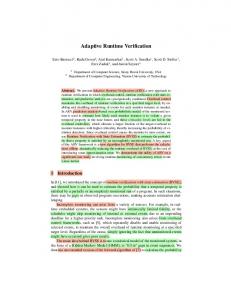
Atomics checkers The purpose of these units is to check the atomic propositions of ψ, one per unit. Ideally, we would favor a full-fledged hardware-only solution allowing for arbitrary atomic propositions to be checked on-the-fly. However, as we aim at a lightweight monitor with small area overhead, we opted for offering two implementation variants: a software-implemented offline checker supports arbitrary expressions for atomics, and we use constraints similar to Logahedra [16] for the hardware-based online approach, thus allowing to establish a balance between hardware complexity and expressiveness. More specifically, the hardware-based atomics checker supports conjunction of restricted two-variableper-inequality constraints of the form (±2n · ri ± 2m · rj ) ./ C where ri , rj ∈ Mem, C ∈ Z, n, m ∈ Z, and ./ ∈ {=, 6=, ≤, ≥, }. The second operand is optional, thus allowing range constraints of the form ±(2n ) · ri ./ C. Fig. 2 shows the generic hardware design to evaluate a single atomic proposition. The unit is connected to the data interface. We instantiate one such unit for each ap ∈ AP ; the derived verdicts atomic(0 . . . |AP |) serve as input for the ptLTL observer. The constant C is loaded into the compare unit; mode constitutes control signals to determine the operation to be performed on the operands. The write-enable signal issued by the CPU triggers the atomics checker unit which stores the value on the data bus in a register iff the destination address equals i or j, respectively. The shifter unit supports multiplication and division by 2n . The arithmetic unit is a full-adder, serving both as adder and subtracter. Observe that, when Add(hai, hbi, c) is a ripple carry adder for arbitrary length unsigned vectors hai and hbi and c the carry in, then a subtraction of hai − hbi is equivalent to Add(hai, hbi, 1). Relational operators can be built around adders in a similar way [18, Chap. 6].
Synthesized HW ptLTL observer The synthesized ptLTL observer unit subsumes the verdicts of the diverse atomic checker units over the respective AP of ψ into a final decision π |= ψ. While in the offline mode this function is performed in software, a dedicated hardware block is needed for the online mode.
RAM bus RAM we mode constant
Operands register & Mux
Shifter Shifter
Arithm. unit add/subb
Fig. 2. The atomics checker unit
Compare =, 6=, ≤ ≥,
atomic(i)
Housekeeping The hardware monitor unit supports writing the *.hex file under scrutiny into the target system’s PROM and handles communication tasks between FPGA and host application using a high-speed USB 2.0 controller. 3.3
Host Application
The host application is responsible for offline runtime verification. It reads a *.hex binary file and a ptLTL formula ψ. Optionally, compiler-generated debug information is parsed and symbols in the high-level implementation language are related to memory addresses in microcontroller memory. Rather than expressing properties over memory locations within the RAM of the microcontroller, this approach allows high-level implementation symbols to be included in the formula. For example, the formula ↑ foo = 20 is satisfied iff the memory location that corresponds to the variable foo, say, r42 , does not equal 20 in the predecessor state S −1 and equals 20 in the current state S. Therefore, even though the analysis is based on binary code, it is possible to state propositions over high-level symbols, which eases the process of specifying desired properties. δ
State updates State transitions S −1 − → S are performed on each state update δ, received from the event logger. Incoming events are categorized as follows: (i) events that perform plain state updates and (ii) events that alter memory locations used in atomic propositions of the formula. Events in (i) are used to keep a consistent representation of the current microcontroller state, whereas events in (ii) additionally trigger the SW ptLTL observer to derive a new verdict. Event evaluation Atomic propositions are directly evaluated on the current state S, and the resulting verdicts are then forwarded to the observer that decides the validity of formula ψ. Synthesized SW ptLTL observer Whenever the destination address @ of a state update δ matches any memory location in the atomic propositions AP of ψ, the generated software ptLTL observer code is executed and a new verdict is derived. If the property is violated, the unit reports “×” to the user. State updates are in temporal order, thus, it would be possible to store a sequence hδ1 , . . . , δn i of state updates and apply the observer afterwards, decoupled from program execution. However, in our experiments, it was always possible to evaluate the events without time-penalty, i.e., as they occur while the program is running. The stored state space consists only of the current state S.
4
Worked Example
In the remainder of this section, we report on applying our toolset to embedded C code. As an example, we consider a function block specified by the PLCopen
S EStopOut = 0 7 start
1
S EStopOut = 1
8
5 9 6
2
3
4
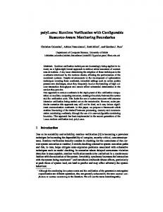
Fig. 3. The emergency stop function block as nondeterministic finite state machine
consortium, which has defined safety-related aspects within the IEC 61131-3 development environment to support developers and suppliers of Programmable Logic Controllers (PLC) to integrate safety-related functionality into their systems. In the technical specification TC5 [28], safety-related function blocks are specified at a high level while the actual implementation is left to the application developer. The emergency stop function block [28, pp. 40 – 45], which we consider in the following, is a function block intended for monitoring an emergency stop button.
Interfaces The function block senses five Boolean inputs, namely Activate, S EStopIn, S StartReset, S AutoReset, Reset and drives three boolean outputs Ready, S EStopOut, Error and one 16-bit wide diagnosis output DiagCode. S EStopOut is the output for the safety-related response.
Requirements The functional description of the block is given by PLCopen as a state diagram [28, p. 42]; Figure 3 shows a simplified version of the state machine (transition conditions and transitions from any state to the idle state (S1 ) have been omitted to make the presentation accessible). Overall, the block comprises nine states, i.e., Idle (S1 ), Init (S2 ), Wait for S EStopIn1 (S3 ), Wait for Reset 1 (S4 ), Reset Error 1 (S5 ), Safety Output Enabled (S6 ), Wait for S EStopIn2 (S7 ), Wait for Reset 2 (S8 ), and Reset Error 2 (S9 ).
Implementation The implementation consists of approximately 150 lines of low level C code targeting the Intel MCS-51 microcontroller. For our experiments, we used the Keil µVision3 compiler. The compiled and linked *.hex file is written into the Intel MCS-51’s PROM, serving as the system under test.
4.1
ptLTL Specification
In the implementation, the 8-bit unsigned variable currState represents the current state, of the function block. An enumeration maps the state numbers {S1 , . . . , S9 } to identifiers. To simplify presentation, we write ΘSx as abbreviation for the event currState = Sx . We proceed by describing two desired properties of the system. Property 1 Predecessors of state Safety Output Enabled (S6 ) are {S2 , S4 , S7 , S8 }, thus, S6 shall not be reached from any other state, which is formalized as: ψ 1 := ↑ (ΘS6 ) → [ ↑ (ΘS2 ∨ ΘS4 ∨ ΘS7 ∨ ΘS8 ), ↑ (ΘS1 ∨ ΘS3 ∨ ΘS5 ∨ ΘS9 ))S The start of event ΘS6 implies that the start of {ΘS2 , ΘS4 , ΘS7 , ΘS8 } was observed in the past; since then, the start of {ΘS1 , ΘS3 , ΘS5 , ΘS9 } was never observed. Property 2 Transitions to the reset states Reset Error 1 (S5 ) and Reset Error 2 (S9 ) shall only originate from Wait for Reset 1 (S4 ) and Wait for Reset 2 (S8 ), thus, have only a single predecessor state. ψ 2 := ↑ (ΘS5 ) → ↓ (ΘS4 ) ψ 3 := ↑ (ΘS9 ) → ↓ (ΘS8 ) The start of event ΘS5 causes the end of event ΘS4 ; the start of ΘS9 causes the end of ΘS8 . 4.2
Online Runtime Verification
We synthesized observers for properties ψ 1 , ψ 2 , and ψ 3 (cf. Fig. 5), both as VHDL hardware description and Java code. We sampled the emergency stop module with different, randomly-generated input patterns and could not find a property violation. To prove our approach feasible, we intentionally altered the next-state code of the state-machine implementation in a way that the transition from S7 to S8 is replaced by a transition from S7 to S9 , thus conflicting with ψ 3 . Error scenario The relevant C code of the implementation is listed in Fig. 4. Whereas the code on the left shows the correct implementation of state Wait for S EStopIn1 (S3 ), the code on the right erroneously introduces a transition to the state Reset Error 2 (S9 ). We first synthesize hardware observers for ψ 1 , ψ 2 , and ψ 3 . Next, the host application configures the atomic checker unit with the atomic propositions that need to be evaluated, that is: ap1 : ap2 :
ΘS8 , (currState = ST WAIT FOR RST2) ΘS9 , (currState = ST RST ERR2)
The (Boolean) verdicts over the atomics are the inputs to the synthesized ptLTL observer, i.e., the vector atomics of the VHDL entity shown in Fig. 5. The Boolean
1 2 3 4 5 6 7 8 9 10 11 12
case ST WAIT FOR ESTOPIn2: Ready = true; S EStopOut = false; Error = false; DiagCode = 0x8004; if (! Activate) currState = ST IDLE; if (S EStopIn && !S AutoReset) currState = ST WAIT FOR RST2; if (S EStopIn && S AutoReset) currState = ST SAFETY OUTP EN; break;
1 2 3 4 5 6 7 8 9 10 11 12
case ST WAIT FOR ESTOPIn2: Ready = true; S EStopOut = false; Error = false; DiagCode = 0x8004; if (! Activate) currState = ST IDLE; if (S EStopIn && !S AutoReset) currState = ST WAIT FOR RST2; if (S EStopIn && S AutoReset) currState = ST RST ERR2; break;
Fig. 4. Emergency stop C implementation; correct(left) and erroneous (right)
output err is raised to true whenever the specification is falsified by the monitor. The sequential process p reset takes care of initialization of the involved registers and the combinatorial process p observer logic implements the actual observer for ψ 3 . We again applied a random input pattern and revealed the erroneous state transition. For example, the sequence S1 � S2 � S6 � S7 � S9 � S6 was shown (by the observer) to be conflicting with specification ψ 3 . 4.3
Offline Runtime Verification
To conclude the example, we also applied our offline approach to the emergency stop example. We thus synthesized a Java class serving as monitor and used the event logger of the hardware monitor unit to offer state updates δ to the host. Likewise, the host application was also able to reveal the erroneous state transition. However, offline runtime verification requires a host computer to be present, whereas our online approach is a self-contained hardware approach.
5
Related Work
As our approach supports software as well as hardware-based monitoring functionality, we categorize related work into software- and hardware-based approaches. Software-based monitoring The commercial tool Temporal Rover [8] allows to check future and past time temporal formulae using instrumentation of source code. Basically, the tool is a code generator that supports Java, C, C++, Verilog or VHDL; properties to be checked are embedded in the comments of the source code. The respective property checks are then automatically inserted into the code, compiled, and executed. Academic tools with automated code instrumentation capabilities are the Java PathExplorer (JPaX) [13], the Monitoring and Checking (MaC) framework [20], and the Requirements Monitoring and Recovery (Rmor) [14] tool. JPaX and MaC facilitate automated instrumentation of Java bytecode; upon execution, they send a sequence of events to an observer. JPaX additionally supports
1 2
library ieee ; use ieee . std logic 1164 . all ;
3 4 5 6 7 8 9 10 11 12 13
entity FORMULA PSI 3 is generic ( ATOMICS LEN : positive := 2; SUBFORMULAS LEN : positive := 5); port ( clk : in std logic ; reset : in std logic ; atomics : in std logic vector (ATOMICS LEN−1 downto 0); err : out std logic ); end FORMULA PSI 3;
14 15 16 17 18
architecture behaviour of FORMULA signal pre reg , pre reg next : std signal now reg, now reg next : std : std signal atomics reg
PSI 3 is logic vector (SUBFORMULAS LEN−1 downto 0); logic vector (SUBFORMULAS LEN−1 downto 0); logic vector (ATOMICS LEN−1 downto 0);
19 20
begin
21 22 23 24 25 26 27
p observer logic : process(pre reg, now reg, atomics reg) variable pre reg next v : std logic vector (SUBFORMULAS LEN−1 downto 0); variable now reg next v : std logic vector (SUBFORMULAS LEN−1 downto 0); begin pre reg next v := pre reg ; now reg next v := now reg;
28 29 30 31 32 33 34
now reg next v(4) now reg next v(3) now reg next v(2) now reg next v(1) now reg next v(0) pre reg next v
:= := := := := :=
atomics reg(0); not now reg next v(4) and pre reg next v(4); atomics reg(1); now reg next v(2) and not pre reg next v(2); not now reg next v(1) or now reg next v(3); now reg next v;
35 36 37 38
pre reg next