International Journal of Information Technology and Knowledge Management January-June 2011, Volume 4, No. 1, pp. 1-5
PATTERN CLASSIFICATION OF PARTIAL DISCHARGE IN LV WINDING OF 1- TRANSFORMER USING PCA Ganesh Rao1 & Shailja Shukla2
Partial discharge is the commencement of failure of insulation of electrical devices used at high voltage. If such discharge is not detected then fault may increase at the working duration. Basically partial discharge is the cause of failure of insulation in electrical equipment. The insulation of electrical equipment deteriorates due to thermal, mechanical, electrical and environmental stresses. Continuous on-line monitoring of partial discharge (PD) activities involves recording large amounts of data and it is hallenging task to extract useful information from them. This paper proposes a partial discharge analysis and its pattern classification in LV winding of single phase Transformer using straight or electrical technique for analysis and principle component analysis algorithm for recognition of partial discharge pattern. Getting different patterns by changing fault location, we can classify these patterns according to their position in the LV winding. To measure the partial discharge we have different technique like direct or electrical method, acoustic measurement, balance. In this paper electrical method is used in which PD Analyzer DDX-9101 is used in which we get the 2-D pattern in sinusoidal waveform at different voltage level by changing location of fault in LV winding. When we vary voltage level with changing location of fault in LV winding we get variation in peaks level and also peaks location i.e. in +ve and –ve half cycle. By analysis of these peaks level and peaks location at different fault location we can analysie these pattern and also recognize or classify these partial discharge pattern with the help of principle component analysis (PCA) algorithm. It has been concluded that the discharge magnitude (PD level) will be very low if fautl is at near supply end, as we go onwards to the supply end discharge magnitude will increase. Keyword: LV Winding of 1 – Φ Transformer, PD Analyzer (DDX-9101), 2-D Partial Discharge Patterns, Principle Component Analysis (PCA) Algorithm
1. INTRODUCTION The steep increase in the demand for electric power necessitates the introduction of higher capacity power equipment with increased voltage rating. The reliability of such equipment is very important, as an unplanned outage of any equipment causes a heavy replacement cost, in addition to the loss due to power shut down from the reliability point of view, an insulation structured is considered as a key factor, moreover, the high cost of insulation necessitates insulation optimization. An insulation system is seldom made from a single material. Often it is made up of few insulating material. Obviously the electrical stress within the system is never uniform and a material with low dielectric constants viz. an air gap is more stressed. If such a gap does not able to with stand the stress, then flash over takes place. Since the discharges occur partially in the insulation system, they are known as Partial Discharges (PD) that can occur in the insulation. Partial discharge detection and measurement in EHV equipment during manufacturing period plays very
important role in order to predict the severity with which insulation system is functioning. Also it is necessary for a practicing to engineer to understand the cause, behavior of partial discharges and the associated measurement techniques. Partial discharge is the commencement of failure of insulation of all electrical devices those are used at high voltage. If such discharge is not detected it will lead to failure of insulation. It begins with voids, cracks, bubbles etc. for different insulation materials such as solid, liquid and air the level of discharge, the breakdown voltage is different. By various techniques Partial discharge can be detected and measured. Acoustic measurement, straight detection, balance detection are commonly used techniques. In our experiment we detected it through straight detection technique. Under it we used PD detector DDX - 9101 type device that gives the PD voltage, charge, and waveform. The results were recorded and compared in a table as well as in a graph which shows how P.D. varies at different voltages for different materials.
1
M.E. (Control System), JEC, Jabalpur
2. WHAT IS PARTIAL DISCHARGE
2
Electrical Engg. Deptt., JEC, Jabalpur
A partial discharge defined as localized discharged in which the distance between two electrodes is only partially bridged
Email:
[email protected],
[email protected] 1
2
2
GANESH RAO & SHAILJA SHUKLA
i.e. the insulation between the two electrodes is partially punctured. Partial discharge may originates at one of the electrode or occur in a cavity in the dielectric.
4.
Discharge Detector: It is a device or an instrument used for either detecting or measuring the discharges[12].
The air or gas cavities are one of the most wide spread types of localized defect. Due to the fact that the dielectric permittivity of air is few times less than the dielectric filed intensity in the gas layer can considerably exceed the average field intensity in the insulator [11].
When a partial discharge occurs the event may be detected as a very small change in the current drawn by the sample under test. PD currents are difficult to measure because of their small magnitudes and short duration.
Therefore in the no. of cases ionization process start even the working voltage. The sum total of this ionization process is called the “partial discharge” since they cover a small part of total distance between the electrodes.
3. NEED OF DETECTION OF PD
Once begin PD causes progressive deterioration of insulating materials ultimately leading to electric breakdown. PD can be prevented through careful design and material is confirmed using PD detector equipment during the manufacturing stage as well as periodically through the equipments useful life. PD prevention and detection are essential to ensure reliable, long term operation of HV equipment used by electric power utilities[12]. Terminology used: 1.
Electric Discharge: The movement of electrical charges through and insulating medium, initiated by electron avalanches.
2.
Partial Discharge: An electrical discharge that only partially bridges the dielectric insulating medium between two conductors. Examples are: internal discharges, surface discharges, corona discharges.
Internal discharges are discharges in the cavities or voids which lie inside the volume of the dielectric or at the edges of conducting inclusions in a solid or liquid insulating media. Surface discharges are discharges from the conductor into a gas or a liquid medium and form on the surface of the solid insulation not covered by the conductor. Corona discharges are a discharge in a gas or liquid insulator around the conductors that are away or remove from solid insulation. 1.
Discharge Inception Applied Voltage: This is the lowest voltage at which discharges of specified magnitude will occur when an increasing a.c. voltage is applied.
2.
Discharge Extinction Applied Voltage: This is the lowest voltage at which discharges of specified magnitude will appear when an applied a.c. voltage, which is more than the inception voltage, is reduced.
3.
Discharge Magnitude: It is the quantity of charge, as measured at the terminals of sample due to a single discharge.
Partial discharge which in course of time reduce the strength of insulation, leading to a total or partial failure or breakdown of the insulation. Measurement of partial discharge on a regular basis can detect failure that would have occurred on account of, 1.
Thermal deterioration;
2.
Load cycling;
3.
Loose winding in the slot;
4.
Contaminated winding tracking.
Whenever there are voids in the insulation, there is a certain voltage existing across the gap. This causes electrical breakdown in the voids as soon as the gradient is around 2.7 to 3.0 KV per mm. When electrical breakdown occurs, the void keeps on enlarging, leading to ultimate failure of insulation. Partial discharge measurement should be carried out at least twice a year. The frequency of carrying out partial discharge measurement depends on the rated voltage of motor[11]. The measurement of PD current pulses provides important information concerning the discharge process in a test specimen. The time response of the fault and design of insulating material. The shape of circular current is an indication of physical discharge process at the fault location in the test object.
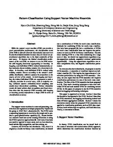
4. EXPERIMENT SETUP To measure the partial discharge pattern by electrical method the experiment set up is shown in fig. 1.In this paper DDX9101 PD analyzer are used to take the 2-D partial discharge pattern of 1-Φ LV winding with capacitor coupled circuit, high voltage generator and high voltage switch plate[2].
Fig.1: PD Measuring System Diagram[10]
PATTERN CLASSIFICATION
OF
PARTIAL DISCHARGE
IN
LV WINDING
OF
1-Φ TRANSFORMER USING PCA
3
By varying the voltage level from the auto transformer and potentiometer and changing the fault location we take the partial discharge patterns waveshape in sinnusoidal form. These experiments is conducted in high voltage lab of Electrical Engg. Department of Jabalpur Engineering College, Jabalpur.
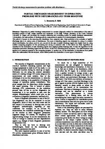
Fig. 2: Tested LV Winding
5. PD ANALYSIS In this paper partial discharge pattern in LV winding of single phase transformer analyzed creating different fault in different location of LV coil. In fig. 3 list of different pattern with changing location of faults are given. In table given below, when coil is in healthy condition partial discharge level is much low (.607 nc) also partial discharge pattern wave shape showing minimum amount of peaks level at constant voltage 20 KV. But in foulty condition (the black sign in coil showing the fault location) at the supplying end the partial discharge level increases also peaks are increase in both positive and negative half cycle.In these wave shape, green color indicates discharge activity that is being measured on the PD meter and red color indicates a section of display that falls within the horizontal gate period, as set up using the “gating” menu option on the scope mode menu. As we increase the fault level, the discharge magnitude will increase and the partial discharge pattern wave shape will change but with the increasing fault level and magnitude of partial discharge it is not necessary that the peak level, peaks quantity will increase. It will change its location, length and section only. Also the discharge magnitude for the fault near supply end is very low (37.91 nc) as we go onwards to the coil discharge magnitude will increase rapidly[3].
6. INTRODUCTION TO PCA Principal Component Analysis (PCA) is a very popular data pre-processing algorithm for simplifying a dataset by reducing a complex dataset to lower dimensions for analysis. It still effectively retains the characteristics of the dataset while having simplified structure and able to reveal underlying features in the dataset [7].
Fig. 3: PD Pattern According to Fault Location
Fundamentally, PCA is a linear transformation that projects the input data to a new coordinate system. The greatest variance by any projection of the data becomes the first principal component; the second greatest variance becomes the second principal component and so on. The lower order components will be the ones to keep as they retain most of the important aspects of the dataset. The mathematical steps for doing the PCA are presented in the following[9].
4
GANESH RAO & SHAILJA SHUKLA
Consider PCA is being performed on an input data array C(M × N). It has M input dimensions and N number of samples. 1.
The input data C is firstly processed by subtracting off the mean for each dimension to get a centered observation.
2.
Find the covariance matrix: C = 1/(N – 1 ). X.XT
3.
By solving the eigenvalue equation λν = Cν, the eigen value λ(M × 1) and eigen vector ν(M × M) are found.
4.
The eigen value λ is sorted in decreasing order with the eigenvector v following the sorting.
5.
The projection of the input data X to the new coordinates is computed: P = νT.C.
6.
The Euclidean distance computed between training data and input data.
7.
Euclidean distance algorithm will find different distance between all training set and input data.minimum distance will show the output image or pattern.
Each row of the projection P re presents the principal components, with a lower order in the top row and higher order in the bottom row[6].
7. RESULTS This paper presents an on line method for analysis of fault detection and its classification in transformer winding using partial discharge analyzer DDX – 9101 and using principle component analysis algorithm. In this paper we analyzed the electrical or direct method of partial discharge analysis by locating fault in transformer and other electrical equipment. In this particular method, we can detect the fault location and discharge magnitude of the equipment by PD analyzer DDX-9101. In this partial discharge analyzer we get direct partial discharge magnitude, voltage level and wave shape by which we can easily analyze the fault location. We can see the wave shape at healthy condition showing no peaks in any section,on the other hand when we create faults at different locations, we get partial discharge waveshapes with peaks in different sections. Also the discharge magnitude for the fault near supply end is very low (37.91 nc) as we go onwards to the coil discharge magnitude will increase rapidally. The green color of Wave shape indicates discharge activity that is being measured on the PD meter and red color indicates a section of display that falls within the
horizontal gate period, as set up using the “gating” menu option on the scope mode menu.
8. CONCLUSION Partial discharge measurements are very popular for the monitoring of the condition of the installation and they have become essential in the quality assessment of the insulation. By means of partial discharge analysis, we can easily avoid unexpected in-service failures, improve the overall reliability of system.The discharge analysis is an efficient device which allows customers to avoid failures and to reduce their maintenance costs. This analysis is used to identify deterioration mechanisms such as slot discharge, internal voids, wedge and winding looseness. Two final studies, noise suppression and field-testing, are required before the system can be deployed in the field. The data from such tests would then allow a commercial company to take on the manufacture and installation of this system in High voltage equipment.
9. ACKNOWLEDGMENT The author would like to thank HV Lab of Electrical Engg. Department, Jabalpur Engg. College Jabalpur TEQIP,TIFAC CORE for providing the facility to collect valuable field test data.
REFRENCES [1]
Borsi, H., 2000, “A PD Measuring and Evaluation System Based on Digital Signal Processing,” IEEE Transactions on Dielectrics and Electrical Insulation, 7, No. 1, pp. 2129.
[2]
High-Voltage Test Techniques Partial Discharge Measurements, IEC 60 270, 2001.
[3]
N.H. Ahmed, N.N. Srinivas, 1998, “On-line Partial Discharge Detection in Cables”, IEEE Trans. Diel. Elect. Insul., 5, No. 2, pp. 181-188.
[4]
M. Hanai, F. Endo, S. Okabe, T. Kato, H. Hama, M. Nagao, 2006, "New Development for Detecting Partial Discharge using an UHF Method and its Application to Power Apparatus in Japan”, Presented at CIGRE Session, Paris, Franlce, Paper Nr. D1-106.
[5]
S. M. Hoek, U. Riechert, T. Strehl, S. Tenbohlen, 2007, “New Procedures for Partial DischargeLocalization in Gas Insulated Switchgears in Frequency and Time Domain”, 15th International Symposium on High Voltage Engineering, Ljubljana, Slovenia (Accepted).
[6]
Abdul Rahman, M.K., Arora, R., and Srivastava, S.C. (2000), “Partial Discharge Classification using Principal Component Transformation”, IEE Proceedings of Scientific Measurement Technologies, 147, No. 1, pp7-13.
PATTERN CLASSIFICATION
OF
PARTIAL DISCHARGE
IN
[7]
Duda, R. O., Hart, P. E., and Stork, D. G. (2000), "Pattern Classification", John Wiley & Sons, Inc., New York, NY.
[8]
Kitter, J. (1978), “Feature Set Search Algorithm”, Pattern Recognition and Signal Processing, Sithoff and Noordhoff, Alphen ann Den Riju, The Netherlands, pp41-60.
[9]
K.X.Lai, B.T.Phung, T.R. Blackburn, “Partail Discharge Analysis using PCA and SOM”, Paper ID:499.
LV WINDING
OF
1-Φ TRANSFORMER USING PCA
5
[10] Mang-hui Wang,” Partial Discharge Pattern Recognition of Current Transformer using an ENN", IEEE Transaction on Power Delivery, 20, No. 3, July 2005. [11] F.H. Kreuger, E. Gulski and A. Krivda, “Classification of Partial Discharges”, IEEE Trans. on Electrical Insulation, 28, 1993, pp. 917-931. [12] R. Bartnikas, "Partial Discharge Measurement IEEE Trans", Elec. Insul.