Performance of Multi-tenant Virtual Networks in OpenStack-based Cloud Infrastructures Franco Callegati, Walter Cerroni, Chiara Contoli
Giuliano Santandrea
DEI - University of Bologna - Cesena, Italy Email: {franco.callegati, walter.cerroni, chiara.contoli}@unibo.it
CIRI ICT - University of Bologna - Cesena, Italy Email:
[email protected]
Abstract—Future network architectures based on the emerging Network Function Virtualization and Software Defined Networking paradigms will significantly rely on cloud computing infrastructures, taking advantage of virtualization technologies. Performance of multi-tenant virtual networks will then be a key aspect to be considered when designing such cloud-based architectures. This issue is investigated in this paper with reference to the widely adopted OpenStack cloud infrastructure management platform. In particular, the paper provides an insight on how OpenStack deals with multi-tenant network virtualization and evaluates its performance in an experimental test-bed.
I. I NTRODUCTION Network virtualization is a key feature in cloud computing infrastructures, since it brings great advantages in terms of flexible network management performed at the software level and possible coexistence of multiple customers sharing the same physical infrastructure (i.e., multi-tenancy). Wellestablished network virtualization solutions are implemented at different protocol layers, including Virtual Local Area Networks (VLANs), multi-layer Virtual Private Network (VPN) tunnels over public wide-area interconnections, and Overlay Networks [1]. Nonetheless, the emerging Network Function Virtualization (NFV) [2] and Software Defined Networking (SDN) [3] paradigms, together with the evolution of cloud computing, are fostering new forms of virtualization of network components and functions that will definitely change the shape of future network architectures. This approach brings forward new opportunities, but also challenges in terms of components integration, management and performance. For instance, any set of virtual networks (typically VLANs) defined in the physical switches within a data center must be integrated with the specific virtual network technologies adopted internally by the hosting servers. Similarly, at the IP layer the coexistence of different IP networks devoted to multiple tenants must be seamlessly guaranteed with proper isolation. All these issues must be addressed by the cloud infrastructure management platforms, which evolved in the last few years on the urge of increasing demand for cloudbased applications. Besides proprietary implementations and products, the open-source software community developed a number of Linux-based virtualization and cloud management tools, including the OpenStack platform. This manuscript aims at providing insights on how OpenStack implements multi-tenant network virtualization, focusing in particular on the performance issue. To the best of our
knowledge, very little has been reported about the actual performance limits of network virtualization in cloud platforms, mainly investigating the case of public cloud services [4]. Our objective is to provide an assessment of the performance as seen from inside the cloud. Therefore, a set of experiments to evaluate the OpenStack performance under a case study inspired by the NFV paradigm in a multi-tenant scenario has been set up, and the related results are here reported. The paper is structured as follows: the OpenStack virtual network architecture is explained in detail in Section II; the experimental test-bed we have deployed to assess its performance is illustrated in Section III; the results obtained under different multi-tenant scenarios are discussed in Section IV; some conclusions are finally drawn in Section V. II. V IRTUAL N ETWORKS
IN
C LOUD I NFRASTRUCTURES
A. Main issues and building blocks Modern communication infrastructures for cloud computing adopt advanced network virtualization techniques, representing one of the most rapidly evolving scenarios where novel network control and management paradigms, such as SDN and NFV, can be deployed. On the one hand, the NFV initiative focuses on the network service implementation and goes in the direction of defining standard virtual building blocks to implement flexible service chains capable of adapting to the rapidly changing user requirements [2]. On the other hand, SDN focuses on network operations and de-couples the data/forwarding plane from a logically centralized control plane, thus providing a more flexible and programmable control of network devices [3]. Moreover, the SDN control plane offers cross-layer interaction capabilities that allow to easily define and manage multiple virtual network slices. As previously outlined, two major issues in cloud infrastructures are: (i) integration of the physical network with the virtual networks implemented inside the servers to interconnect virtual machines (VMs) as required; and (ii) isolation among networks that must be logically separated because devoted to different purposes or dedicated to different customers. Serverside network virtualization is typically implemented by the VM manager (i.e., the Hypervisor) running on the hosts. At layer 2 the previous two goals are achieved exploiting VLAN technology. The VLANs defined in the physical switches are integrated with the specific virtual network technologies adopted by the hosting servers. Layer-
2 switching is typically implemented by means of kernellevel virtual bridges/switches interconnecting the VM’s virtual interface to the host’s physical interface. The most noteworthy virtual bridging solutions adopted by Hypervisors running on Linux systems are Linux Bridge (LB), the native kernel bridging module [5], and Open vSwitch (OVS), a distributed, OpenFlow-enabled, software-based switching facility capable of reaching kernel-level performance [6]. With respect to LB, OVS was specifically designed to be flexible enough to implement a virtualized cloud networking environment, where aspects such as multi-tenant traffic isolation, transparent VM mobility and fine-grained forwarding programmability are considered critical [7]. At layer 3 the two goals are achieved using lightweight virtualization tools, such as Linux Containers, or defining multiple network namespaces within a single host, resulting in isolated virtual networks with dedicated Linux network stacks (e.g., IP routing tables, netfilter flow states, etc.) [8]. B. The OpenStack case OpenStack is one of the most popular and widely adopted open-source implementations of the Infrastructure as a Service (IaaS) cloud paradigm [9]. It provides a powerful and flexible dashboard to control a cluster of hosting servers executing different kinds of Hypervisors, and to manage the required storage facilities and virtual network infrastructures. A typical OpenStack cluster includes the following nodes: • a controller node, managing the cloud platform; • a network node, hosting the cloud networking services; • a number of compute nodes, executing the VMs; • a number of storage nodes, for data and VM images. The OpenStack software component specifically dedicated to network service management is called Neutron. A centralized Neutron server stores all network-related information, whereas the Neutron agents running in the network node and in each compute node implement the virtual network infrastructure in a coordinated way. This allows Neutron to transparently manage multi-tenant networks over multiple compute nodes. Taking advantage of Neutron’s network abstractions, cloud customers can use the OpenStack dashboard to quickly instantiate computing and networking resources within a virtual data center infrastructure. More specifically, an OpenStack user, representing a given tenant, is allowed to create a new layer-2 network and to define one or more layer-3 subnets on top of it, optionally spawning the related DHCP server in charge of IP address distribution. Then the user can boot a new VM instance, specifying the subnet (or subnets) it has to be connected to: a port on that subnet (and related network) is created, the VM is connected to that port and a fixed IP address is assigned to it via DHCP. Other virtual appliances, such as a router providing global connectivity and address translation (NAT) functions, can be implemented directly in the cloud platform by means of containers and namespaces typically defined in the network node. Isolation among different tenant networks is guaranteed by the use of VLANs and namespaces,
Fig. 1. Network elements within an OpenStack network node. Three OVS bridges (red boxes) are interconnected by veth pairs (grey boxes). br-data and br-ex are attached to their respective physical interfaces (eth1 and eth2).
Fig. 2. Network elements within an OpenStack compute node running two VMs. Two LBs (light-blue boxes) are attached to the VM tap interfaces (green boxes) and connected by veth pairs to the OVS integration bridge (br-int).
whereas the security groups protect the VMs from external attacks or unauthorized access. The virtual network infrastructure implemented by OpenStack is composed of multiple virtual bridges connecting both virtual and physical interfaces, as shown in Figs. 1 and 2 with the help of an ad-hoc graphical tool we developed to display all network elements used by OpenStack [10]. Each node runs an OVS-based integration bridge named br-int and, connected to it, an additional OVS bridge for each data center physical network attached to the node. So the network node (Fig. 1) includes br-data for the data network, where the multitenant virtual networks are operated, and br-ex for the external network. A compute node (Fig. 2) includes br-data only, as it is typically connected to the data network only. Layer 2 virtualization and multi-tenant isolation on the
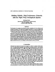
Fig. 3. Multi-tenant NFV scenario tested on the OpenStack platform.
physical data network can be implemented using either VLANs or layer-2-in-layer-3 tunneling solutions, such as Virtual eXtensible LAN (VXLAN) or Generic Routing Encapsulation (GRE), that allow to extend the local virtual networks also to remote data centers [7]. Whatever virtualization technology is used in the physical data network, its virtual networks must be mapped into the VLANs used internally by Neutron to achieve isolation. This is performed by taking advantage of the programmable features available in OVS through the insertion of appropriate OpenFlow mapping rules in br-int and br-data. When a user creates a new VM instance, for each subnet/network the VM is connected to, a group of virtual network elements are created: a LB (along with its management interface), a virtual Ethernet (veth) interface pair connecting the LB to the integration bridge, and a tap interface that connects the VM running in user-space to the kernel-level LB. In principle, the tap interface could be connected directly to the integration bridge. However, the security groups currently implemented by Neutron adopt the native Linux kernel filtering functions (netfilter) applied to bridged tap interfaces, and this works only with LBs. III. E XPERIMENTAL S ETUP In order to assess the performance of OpenStack’s virtual network infrastructure when multiple tenants are simultaneously active, we have deployed a small test-bed including a controller node, a compute node and a network node. The compute node runs KVM, the native Linux VM Hypervisor, and is equipped with 8 GB of RAM and a quad-core processor enabled to hyper-threading, resulting in 8 virtual CPUs. The multi-tenant scenario we want to analyze is inspired by a simple NFV case-study, as illustrated in Fig. 3: each tenant’s service chain consists of a customer-controlled VM followed by a deep packet inspection (DPI) virtual appliance, deployed by the cloud service operator as a separate VM with two network interfaces, running a traffic monitoring application based on the nDPI library [11]. All traffic exchanged by the customers is subject to DPI processing, a common practice among Internet service providers to enforce network security and traffic policing. The NFV approach allows to flexibly deploy and customize the virtual DPI function based on the given tenant characteristics. Then multiple tenant slices are
Fig. 4. Multi-tenant virtual network view from the OpenStack platform dashboard. Each tenant slice includes a VM connected to an internal network (InVMneti) and a second VM performing DPI and packet forwarding between InVMneti and DPIneti. The virtual router in the bottom-left corner provides connectivity between each DPIneti and the public network.
connected to the virtual router for packet forwarding and NAT operations. As per OpenStack architecture, all the VMs are running in the compute node, the role of the virtual router is performed by the network node within a dedicated network namespace, and all layer-2 connections are implemented by a virtual switch (with proper VLAN isolation) distributed in both the compute and network nodes. Figure 4 shows the virtual network view from the OpenStack controller node dashboard when 4 tenants are simultaneously active. In our small experimental setup we limit the investigation to no more than 4 tenants, which are enough to put the hardware executing the compute node under stress. The VM setup shown in Fig. 3 is not commonly seen in a traditional cloud computing environment, where VMs typically act as simple hosts connected as end-points to one or more virtual networks. However, the NFV paradigm is very likely going to change this approach and require that some VMs perform network functions involving packet forwarding among multiple network segments, as in our DPI example. But such a change of role breaks some of the rules imposed by
100
Single Tenant 2 Tenants - T1 2 Tenants - T2 3 Tenants - T1 3 Tenants - T2 3 Tenants - T3 4 Tenants - T1 4 Tenants - T2 4 Tenants - T3 4 Tenants - T4
90 Traffic received per tenant [Kpps]
OpenStack’s security groups. For instance, when a new VM is instantiated by OpenStack, filtering rules to avoid MAC and IP spoofing are added to the LB attached to the VM’s tap interface. These rules do not allow packets to come out of the VM if the source MAC and IP addresses are different from the ones assigned to the VM itself, making it impossible for a VM to forward packets generated by another VM. To solve this issue, we have modified the filtering rules in our OpenStack deployment by allowing, within each tenant slice, packets coming from or directed to the customer VM’s IP address to pass through the LBs attached to the DPI virtual appliance. These new rules have been added to both IP-level and bridge-level Linux native firewalls: in fact, in addition to the anti-spoofing filter placed by OpenStack at the IP forwarding level using the iptables command, a similar filter is placed by KVM at the LB level by means of the ebtables command. We have also had to extend the virtual router’s NAT function to the whole set of internal networks used in our multi-tenant setup.
80 70 60 50 40 30 20 10 0 0
10
100
1 In fact the single compute node has to process the workload of all the components involved, including packet generation and DPI in the VMs of each tenant, as well as layer-2 packet processing and switching in three LBs per tenant and two OVS bridges.
30 40 50 60 70 Traffic generated per tenant [Kpps]
80
90
100
Fig. 5. Received vs. generated packet rate for each tenant (T1, T2, T3 and T4), for different numbers of active tenants, with 1500-byte IP packet size.
IV. R ESULTS
Single Tenant 2 Tenants - T1 2 Tenants - T2 3 Tenants - T1 3 Tenants - T2 3 Tenants - T3 4 Tenants - T1 4 Tenants - T2 4 Tenants - T3 4 Tenants - T4
90 Traffic received per tenant [Kpps]
The performance of the OpenStack virtual network infrastructure is assessed by measuring, at an external destination, the packet rate and throughput received from traffic sources running in each customer VM and generating packets at increasing rate, for different numbers of simultaneously active tenants. Each source generates UDP traffic ranging from 103 to 105 packets per second (pps), for both 64 and 1500-byte IP packet sizes. The RUDE & CRUDE tool is used for traffic generation and measurement [12]. All physical interfaces used in our experiments are Gigabit Ethernet network cards. Figures 5 and 6 show the packet rate actually received at the destination from each tenant as a function of the packet rate generated by each tenant, for different numbers of simultaneously active tenants, with 1500 and 64-byte IP packet size respectively. For a given number of tenants, each one of them generates the same amount of traffic, resulting in as many overlapping curves as the number of active tenants. All curves grow linearly with the injected packet rate, as long as the generated traffic is sustainable. Then, two different saturating effects take place. The sharp saturation shown in Fig. 5 for 1500-byte packets is caused by the bandwidth limit imposed by the Gigabit Ethernet physical interfaces. In fact, the curves become flat as soon as the packet rate reaches about 80 Kpps for 1 tenant, about 40 Kpps for 2 tenants, about 27 Kpps for 3 tenants, and about 20 Kpps for 4 tenants, i.e. when the total packet rate is slightly more than 80 Kpps, corresponding to 1 Gbps. The smoother saturation shown in Fig. 6 for the 64-byte packet size is not caused by the bandwidth limit but by the inability of the hardware platform to cope with the packet processing workload.1 A total of 150 Kpps with 64-byte
20
80 70 60 50 40 30 20 10 0 0
10
20
30 40 50 60 70 Traffic generated per tenant [Kpps]
80
90
100
Fig. 6. Received vs. generated packet rate for each tenant (T1, T2, T3 and T4), for different numbers of active tenants, with 64-byte IP packet size.
packets results in a total bit rate of about 77 Mbps, well below 1 Gbps. Therefore the virtual network is not able to use the whole physical capacity, even in the case of just one tenant. The interesting result is that this penalty increases with the number of tenants (i.e., with the complexity of the virtual system). With two tenants the curve saturates at a total of approximately 150 Kpps (75 × 2), with three tenants at a total of approximately 135 Kpps (45 × 3), and with four tenants at a total of approximately 120 Kpps (30 × 4). This is to say that an increase of one unit in the number of tenants results in a decrease of about 10% in the usable network capacity. The presence of different saturating effects depending on the packet size is confirmed by the curves shown in Fig. 7, where the total throughput measured at the destination is plotted as a function of the total packet rate, for different numbers of simultaneously active tenants. Since all total values are computed by summing the contributions from all the active tenants, the curves for 1, 2 and 3 tenants stop at 100, 200
100 1000
Total throughput received [Mbps]
Total throughput received [Mbps]
90
100
4 Tenants - 1500 bytes 3 Tenants - 1500 bytes 2 Tenants - 1500 bytes Single Tenant - 1500 bytes 4 Tenants - 64 bytes 3 Tenants - 64 bytes 2 Tenants - 64 bytes Single Tenant - 64 bytes
10
1 0
50
100
150 200 250 300 Total traffic generated [Kpps]
350
80 70 60 50 40 30 3 Tenants (LB bypass) 4 Tenants (LB bypass) 2 Tenants 3 Tenants 4 Tenants
20 10 0
400
0
50
100
150 200 250 Total traffic generated [Kpps]
300
350
400
Fig. 7. Total throughput measured vs. total packet rate generated by 1 to 4 tenants for 1500 and 64-byte packet size. The curves are plotted in logarithmic scale due to the large difference in range values.
Fig. 8. Total throughput measured vs. total packet rate generated by 2 to 4 tenants for 64-byte packet size. Comparison between normal OpenStack mode and LB bypass with 3 and 4 tenants.
and 300 Kpps respectively. The throughput measured with 1500-byte packets always saturates at 1 Gbps, whereas the maximum throughput obtained with 64-byte packets is limited to a much smaller value, proving that in the latter case the network performance is limited by physical computing resource contention. The difference among the various number of tenants is here less visible because of the logarithmic scale. In Fig. 8 we compare the 64-byte total throughput obtained under normal OpenStack operations with the corresponding total throughput measured when the LBs attached to each VM are bypassed. To implement the latter scenario, we have manually modified the OpenStack virtual network configuration running in the compute node by connecting each VM’s tap interface directly to the OVS integration bridge. The curves show that the presence of LBs in normal OpenStack mode is indeed causing performance degradation, especially when the workload is high (i.e., with 4 tenants). A significant improvement can be achieved bypassing the LBs, as the reduced packet processing burden allows the compute node to successfully cope with higher packet rates, resulting in increased maximum throughput. It is interesting to note also that the penalty related to the number of tenants is mitigated by the bypass, but not fully solved.
architecture poses some limitations to the network performance which are not simply related to the hosting hardware maximum capacity, but also to the virtual network architecture implemented by the OpenStack platform management. Our study demonstrated that some of these limitations can be mitigated with a careful re-design of the virtual network infrastructure, but that such limits must be taken into account for any engineering activity in the virtual networking arena.
V. C ONCLUSION In this work the performance of virtual networking in cloud computing infrastructures was investigated. An OpenStackbased cloud setup was considered, hosting multiple tenants executing a simple NFV-inspired virtual networking architecture in the cloud. The case study considered a chain of deep packet inspection, conventional address translation and routing out of the tenant IP network. The issue of virtual networking setup and integration with physical networks was explored and discussed, and results about the throughput performance of the virtual network were presented. The main outcome is that the cloud-based
ACKNOWLEDGMENT This work was partially funded by EIT ICT Labs, Activity 2013 “Smart Networks at the Edge”, task T1303A - Enable Efficient and Seamless Network-Cloud Integration. R EFERENCES [1] N. M. Mosharaf Kabir Chowdhury and R. Boutaba, “A survey of network virtualization,” Computer Networks, Vol. 54, No. 5, 8 Apr. 2010, pp. 862-876. [2] The European Telecommunications Standards Institute, “Network Functions Virtualisation (NFV): Network Operator Perspectives on Industry Progress,” ETSI White Paper, Oct. 2013. [3] The Open Networking Foundation, “Software-Defined Networking: The New Norm for Networks,” ONF White Paper, Apr. 2012. [4] R. Shea, et al., “A Deep Investigation into Network Performance in Virtual Machine Based Cloud Environments,” In Proc. IEEE INFOCOM 2014, Toronto, ON, Canada, Apr. 2014, pp. 1285-1293. [5] The Linux Foundation, Linux Bridge, 19 Nov. 2009. Available: http: //www.linuxfoundation.org/collaborate/workgroups/networking/bridge [6] B. Pfaff, et al., “Extending Networking into the Virtualization Layer,” In Proc. 8th ACM HotNets, New York, NY, Oct. 2009. [7] R. Jain and S. Paul, “Network Virtualization and Software Defined Networking for Cloud Computing: A Survey,” IEEE Communications Magazine, Vol. 51, No. 11, Nov. 2013, pp. 24-31. [8] N. Handigol, et al., “Reproducible network experiments using containerbased emulation,” In Proc. 8th CoNEXT, Nice, France, Dec. 2012, pp. 253-264. [9] OpenStack project website. Available: http://www.openstack.org [10] G. Santandrea, Show My Network State project website, 2014. Available: https://sites.google.com/site/showmynetworkstate [11] nDPI: Open and Extensible LGPLv3 Deep Packet Inspection Library. Available: http://www.ntop.org/products/ndpi/ [12] RUDE & CRUDE: Real-time UDP Data Emitter & Collector for RUDE. Available: http://sourceforge.net/projects/rude/