Vol. 2 (2012) No. 5 ISSN: 2088-5334
Performance of Parallel Concatenated Convolutional Codes (PCCC) with BPSK in Nakagami Multipath M-Fading Channel Mohamed Abd El-latif, Alaa El-Din Sayed Hafez, Sami H. Darwish Alexandria University, 5H Toson City, Alexandria, Egypt E-mail:
[email protected],
[email protected],
[email protected]
Abstract —in this paper the encoder design of two parallel concatenated convolutional codes (PCCC) have been introduced. Concept of puncturing is also considered. PCCC is also named as Turbo codes. Decoding process of turbo-codes using a maximum a posteriori (MAP) algorithm has been discussed. Different parameters affect the BER performance of turbo codes are introduced .The previous studies focusing on the turbo-codes performance in (AWGN) and Rayleigh multipath- fading channels [1], [2]. The real importance of Nakagami –m fading model lies in the fact that it can often be used to fit the indoor channel measurements for digital cellular systems such as global system mobile (GSM) [3]. In this paper, the BER performance and comparative study of turbo-codes in Nakagami multipath- fading channel is verified using Matlab simulation program. Keywords
— Turbo codes, Interleaver, Feedback Decoder. convolutional encoders joined by an interleaver [6]. The input information bits feed the first encoder, after have been scrambled by the interleaver, and enter the second encoder. The code word of the parallel-concatenated code consists of the information bits followed be the parity check bits of both encoders as shown in Fig.1 depending on the code rate required, the parity bits from the two constituent encoders are punctured before transmission. For example, constituent codes of rate 1/2 and for a turbo code of rate 1/3, all the parity bits are transmitted, whereas, for a turbo- code with rate 1/2, the parity bits from the constituent codes are punctured alternately. For transmission over a fading channel, the coded bits should be further interleaved by a channel interleaver before transmission [7].The goal in designing turbo-codes is to choose the best encoder generator polynomials and a proper interleaver design to maximize the free distance of the code.
I. INTRODUCTION The invention of turbo- codes has been an unprecedented event in the field of communication. Turbo codes have been considered as a powerful error correcting codes for its superior performance so; it takes place in mobile communications area, high data rate internet applications and also in the field of steganography [4]. The design of these codes was a result of an experimental process where simulation was used in order to joint several parameters so as to optimize the finial target, namely the bit error rate (BER) [5]. This paper is structured as follows; section-II introduces the puncture turbo encoder using a random interleaver. We concerned in section-III in Nakagami multipath- fading channel model. In section-IV decoding of turbo codes using feedback structure with Maximum Aposteriori Probability (MAP) algorithm has been investigated. Effect of input data frame length, encoder constraint length and the number of decoding iterations in the BER performance have been performed. Section-V performs the comparative study of BER performance in both Rayleigh and Nakagami multipath fading channels for code rates half and one-third and different Nakagami (m) shaping factor.
Systematic output
Information Bits
II. PUNCTURED TURBO ENCODER
Constituent Encoder no (1)
Random
Turbo-codes have an excellent coding community for their astonishing performance. They are parallelconcatenated convolutional codes (PCCC’s) whose encoder is formed by two or more constituent systematic recursive
Interleaver
Constituent Encoder no (2)
Parity Bit Puncture Parity Bit
Fig.1 General Diagram of Turbo Code Encoder
51
IV. DECODING OF TURBO CODE USING MAP ALGORITHM
Ir = ( M /2 + 1) ( i + j) mod.M
(i j)
(1)
In 1974, an algorithm, which has become known as maximum aposteriori probability (MAP) algorithm by Bahl et al [10].In order to estimate the a posteriori probabilities of the states and the transition of a Markov source observed in memory less channel noise. Bahl et al showed how the algorithm could be used to decode both block and convolutional codes. The basic idea is to break up decoding of a fairly complex and long code into steps while the transfer of probabilities or “soft” information between the decoding steps guarantees almost no losses of information [11]. MAP algorithm provides not only the estimated bit sequence, but also the probabilities for each bit that it has been decoded correctly. The decoder depicted in Fig.2,is made up of two elementary decoders (DEC1 and DEC2) in a serial concatenated scheme . For a discrete memoryless Gaussian channel and binary modulation, the decoder is made up of a couple Rk of two random variables xk and yk , at time k.
(2)
mod.8
jr [ P ( ).( J 1)] 1 mod.M
(3)
Where (ir,jr) are the addresses of line and column for reading This nonuniform reading procedure is able to spread the residual error blocks, this is give a large free distance to the concatenated (parallel) code [1]. III. NAKAGAMI MULTIPATH FADING CHANNEL Nakagami -m distribution is a general probability density function (PDF). In creating a Nakagami–m distribution, Nakagami was able to span with one distribution the entire range from one-sided Gaussian fading (including Rayleigh fading) to a non-fading according to the scale and shape parameters ,m[8]. Nakagami -m distribution is also of great interest to ionospheric physicists because amplitude fading due to ionospheric scintillation has been found following an m-distribution [9].The (PDF) of Nakagami-m can be described as follows:
P (r)
2 m m r 2 m 1 (m )
m
m
e (m / )r
2
xk = (2X-1)+ ik
yk = (2X-1)+qk (11) here ik and qk are two independent noises with the same variance. The LLR, A1(dk) associated with each decoded bit dk from sequences {xk} and {yk} by the first decoder can be expressed as follows:
(4)
E[ r 2 ]
(5)
2 0 .5 var( r 2 )
(6)
A1 (d k ) log
A1 (d k )
xk
(7)
for i=1: m
(8)
Y =Y1+Y2+Y3…………+Ym
(9)
(12)
After LLR computation of A1(dk) by the first decoder, the second decoder DEC2 performs the decoding of sequence {dk} from the sequences {A1(dk)} and {yk}
y1k
where, k is an integer symbol index, xk is a BPSK symbol amplitude ( E S ) , nk is the additive white Gaussian noise (AWGN) component with zero mean and power spectral density N0/2 . The fading amplitude ak follows a Nakagami PDF.The simulation of Nakagami-m fading amplitude can be introduced as follows: Select an appropriate value of the Nakagami- m shaping parameter ,then select m exponentially distributed random variables Y1…..Ym by first generating m uniform random variables X1……Xm and then taking the logarithm. Yi = - log Xi
Pr{d k 1 / observation ) Pr{d k 1 / obseravation )
where, Pr{dk= i/observation}, i = (0,1) is the a posteriori probability (APP) of the bit dk.
for m=1 we have a Rayleigh fading channel, as m increase the channel becomes non-fading, at the other extreme, for m=1/2 we have a one sided Gaussian distribution. For Nakagami -m fading channel with appropriate sampling, the discrete representation is as follows: yk=ak xk +n
(10)
A1 (d n )
16 stages Decoder DEC1
dn 16 stages Decoder DEC2
Interleaver
y2k
Received sequence yk
Fig. 2 Decoding Principle in accordance with serial Concatenation
The global decoding rule is not optimum, because the first decoder uses only the fraction of the available redundant information. Therefore, it is possible to improve the performance of this serial decoder by using a feedback loop A1(dk) can be expressed as follows:
A1 (d k ) log
Y, is gamma distributed so, taking the square root of (Y). then Z=SQRT (Y), where (Z) represent the fading amplitude for Nakagami-m fading channel.
'
'
'
m m'
0 (R k , m , m) k 1 ( m ) k (m) m m'
52
'
1 (R k , m , m) k 1 ( m ) k (m)
(13)
where m, m ' are the present and previous state, is the probability that given the trellis was in state m ' at time k-1 , it moves to state m , is the probability that the trellis is in state m ' at time k-1 for a specific received channel sequence. Finally, is the probability for the received channel sequence given that the trellis at state m at time (k). With the feedback loop the first decoder now has the following three data inputs (xk ,y1k , zk) where zk equal w2k is the extrinsic information from the second decoder .The term turbo-code is given for this feedback decoder scheme with reference to the principle of the turbo engine as shown in Fig.3.
0
10
Half Rate Third Rate -1
BER
10
-2
10
-3
10
-4
10
A 2 (d n )
W2k
A 1 (d k )
10
y2k
Mux
BER
y1k
10
16 States Decoder
16 States Decoder
xk
0.4
0.6
0.8
1
1.2
1.4
1.6
1.8
2
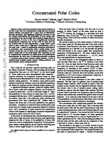
Fig.4 BER Performance Comparison Between One - Third and Half – Rate Turbo-Code
Deinterleaver Zk
0.2
Eb/N0 (dB)
Interleaver
0
10
0
169 bit 1,000 bit 4,000 bit 10,000 bit 65,536 bit
-1
-2
yk
dk
Deinterleaver
Decoded output
10
Fig.3 Feedback Decoder used in Decoding Turbo-Codes 10
-3
-4
0
0.5
1
1.5
2
2.5
3
Eb/N0 (dB)
V. PERFORMANCE OF TURBO CODE IN NAKAGAMI MULTIPATH M- FADING CHANNEL
Fig.5 Effect of Frame – Length on the BER Performance of Turbo-Code
Turbo- codes perform near optimum capacity limit on (AWGN) channel [1]. As a powerful coding technique, turbo-codes offer great promise for improving the reliability of communications over wireless channels where fading is problematic [2]. The BER performance of turbo - codes with code rates 1/2 and 1/3 over a Rayleigh fading channel is shown in Fig (6,7) respectively. It should be noted that for the Rayleigh channel with average energy of unity, EA[a] is equal 0.8862.
The standard parameters used in our simulation can be described as follows: The encoder components are two identical recursive convolutional codes. The recursive parameters are G0 = 7 & G1=5 & K=3 & n=2 & k =1.The component decoder is (MAP) decoder. The number of iteration used in the decoding process (8 iterations), The Nakagami shaping factor m equal(1:3)The interleaver is considered to be 1000 bit random interleaver. The modulation technique is binary phase shift keying (BPSK).Punctured used is half parity bits from each encoder give a half rate code. The input data frame lengths are {1691000-10,000} bit. The effect of the code rate and frame length of input data on the BER performance of turbo-codes over an (AWGN) channel is shown in Fig (4,5) respectively . For wireless applications on fading channels, channel coding is an important tool for improving communications reliability.
10
BER
10
10
10
0
-1
-2
-3
Turbo L=169 Turbo L=1000 Turbo L=10000 10
-4
0
1
2
3
Eb/N0(dB)
4
5
6
Fig.6 BER Performance of Turbo - Code with Different Frame Lengths (L) and Rate 1/2 over Rayleigh Fading Channel
53
10
0
Turbo L=169 Turbo L=1000 Turbo L=10000
BER
10
10
10
10
-1
-2
-3
-4
0
0.5
1
1.5
2
2.5
3
3.5
4
4.5
Eb/N0(dB)
Fig.7 BER Performance of Turbo-Code with Different Frame- Lengths (L) and Rate 1/3 over Rayleigh Fading Channel
Fig .8.a. BER performance of turbo codes with frame length L=169 bit and code rate 1/2 over Nakagami fading channel
The BER performance of turbo –codes in Nakagami multipath m-fading channel with code rate 1/2 for different values of shaping factor m , and different frame lengths is shown in Fg.8 (a,b,c) and for code rate 1/3 in Fig.9 (a,b,c) respectively.For m equal(1) the BER performance obtained is the same as the BER performance over a Rayleigh fading channel. For m=2 additional improvement is occurred, for m equal (3) the BER performance approached the performance over the AWGN channel especially for long frame length of input data where the difference is approximately (0.1) dB as shown in table. I. The turbo code BER performance with rate 1/2 in both Gaussian channel and Nakagami multipath fading channel has been also compared. TABLE I BER PERFORMANCE OF RATE 1/2 TURBO CODES IN BOTH AWGN CHANNEL AND NAKAGAMI MULTIPATH FADING CHANNEL
Data frame length
Fig .8.b. BER performance of turbo codes with frame length L=1000 bit and code rate 1/2 over Nakagami fading channel
(10000) bit (169) bit
(1000) bit
BER
Eb/N0 (dB)
BER
Eb/N0 (dB)
BER
Eb/N0 (dB)
10-4
2.7
10-4
1.8
10-4
1.2
10-4
3.6
10-4
2.3
10-4
1.3
AWGN
Nakagami fading channel with m=3 (Eb/N0) differences in (dB)
0.9
0.5
0.1
Fig 8.c. BER performance of turbo codes with frame length L=10000 bit and code rate 1/2 over Nakagami fading channel
54
The BER performance comparison of turbo codes is listed in tables (II, III). TABLE II BER PERFORMANCE OF RATE 1/3 TURBO CODES IN BOTH RAYLEIGH AND NAKAGAMI FADING CHANNELS Data frame length
169 bit Eb/N0 (dB)
BER
Eb/N0 (dB)
BER
Eb/N0 (dB)
10-4
4.13
10-4
2.3
10-4
1.3
10-4
2.9
10-4
1.7
10-4
1
(Eb/N0)
1.23
differences in (dB)
Fig 9.a. BER performance of turbo codes with frame length L =169 bit and code rate 1/3 over Nakagami fading channel
10000 bit
BER Rayleigh fading channel
Nakagami fading channel with m=3
1000 bit
0.6
0.3
TABLE III BER PERFORMANCE OF RATE 1/2 TURBO CODES IN BOTH RAYLEIGH AND NAKAGAMI FADING CHANNELS Data frame length Rayleigh fading channels Nakagami fading channel with m=3
(Eb/N0)
differences in (dB) Fig .9.b. BER performance of turbo codes with frame length L =1000 bit and code rate 1/3 over Nakagami fading channel
169 bit
1000 bit
10000 bit
BER
Eb/N0 (dB)
BER
Eb/N0 (dB)
BE R
Eb/N0 (dB)
10-4
5.14
10-4
3.85
10-4
3
10-4
3.6
10-4
2.3
10-4
1.3
1.54
1.55
1.7
VI. CONCLUSION The simulation results for the BER performance of turbocodes in different channel models show that: in Nakagami multipath fading channel with code rate 1/2 and shaping factor m equal (3), the BER performance is similar to that obtained over a Rayleigh multipath fading channel with code rate 1/3, it means, the efficient using of channel bandwidth can be obtained without degradation of the BER performance. On the other side, while the BER performance improved as the shaping parameter (m) increased, for (m) greater than (3) no additional improvements have be achieved. REFERENCES [1]
[2] Fig .9.c. BER performance of turbo codes with frame length L=10000 bit and code rate 1/3 over Nakagami fading channel
[3]
55
C. Berrou, A. Glavieux, and P. Thitimajshima. “ Near Shannon limit error correcting coding and dcoding turbo codes” IEEE International Conference on Communications, Geneva, Swit zerland, May 2003. Eric K. Hall and Stephen G. Wilson, “ Design analysis of turbo codes on Rayleigh fading channels” IEEE Journal on selected area in commun, vol. 16, no. 2, pp.160– 174 February 1998. Said M.Elnoubi, “ Statistical modeling of the indoor Radio channels at 10 GHZ through propagation measurements part I Narrow band
[4] [5] [6] [7]
[8]
measurements and modeling ” IEEE Trans. Vehicular technology, vol. 49, no .4, pp . 1 – 18, July 2000. Anil Kumar and Navin Rajpal “Application of T-Code, Turbo Codes and Pseudo-Random Sequence for Steganography” Journal of Computer Science, pp 148-153, 2006. Battail, “ A Conceptual Framework for Understanding Turbo Codes,” IEEE Journal on selected area in commun, vol. 16, no. 2, pp.245– 254 February 1998. S.Benedetto and G.Montorsi, “ Design op parallel concatenated convolutional codes,” IEEE Trans. Commun.,vol.44.pp.591-600, May 1996. J.Hagenauer, “ Iterative decoding of binary block and convolutional codes, ” IEEE Trans.Info. Theory, vol. 42, no .2, pp . 429 – 445, March 1996
[9] [10]
56
I.chatzigeorgiou, M. R. D. Rodrigues, I. J. Wassell and R. Carrasco, "The augmented state diagram and its application to convolutional and turbo codes", IEEE Transactions on Communications, vol. 57, no. 7, pp. 1948-1958, July 2009. Thomas Eng, Laurence B. Milstein, “ Coherent DS-CDMA performance in Nakagami multipath fading,” IEEE Trans. Commun, vol. 43, no .2/3/4, pp. 1134 – 1142, March/April, 1995. I.chatzigeorgiou, M. R. D. Rodrigues, I. J. Wassell and R. Carrasco, "Analysis and design of punctured rate-1/2 turbo codes exhibiting low error floors", IEEE Journal on Seleced Areas in Communications, Special Issue on Capacity Approaching Codes, vol. 27, no. 6, pp. 944-953, August 2009”