from simple ones such as linear connections (snakes), loops, to legged creatures (Fig. ... The initial state is marked by an arrow pointing to it, labeled by initial phase delay. .... [7] S.M. Song and K.J. Waldron, Machines that Walk: The. Adaptive ...
Phase Automata: A Programming Model of Locomotion Gaits for Scalable Chain-type Modular Robots Ying Zhang, Mark Yim, Craig Eldershaw, Dave Duff and Kimon Roufas Palo Alto Research Center 3333 Coyote Hill Road Palo Alto, CA, 94304, USA Email: {yzhang,yim,celdersh,dduff,kroufas}@parc.com Abstract − Modular reconfigurable robots have shown the promises of great versatility and robustness; however programming locomotion gaits for hundreds of modules remains a challenge. In this paper we present a formal model for programming locomotion gaits in chain-type modular robots: Phase Automata. A phase automaton is an event-driven state automaton with an initial phase delay. The phase delay is normally a real value between 0 and 1. Phase automata are compact representation of locomotion gaits and capable of being embedded and distributed across modules. The concepts of phase automata have been implemented on both PCs and embedded micro-processors. An XML script language and programming interface for phase automata are being built. Locomotion gaits programmed using phase automata have been tested both in simulation with 100+ modules and in hardware with 50+ modules. 1. INTRODUCTION AND MOTIVATION Modular self-reconfigurable robotic systems are those systems that are composed of modules that can disconnect and reconnect themselves automatically in different arrangements to form a new shape with different functionalities. In many cases, the total number of modules is much larger than the number of different module types within such systems, i.e., the systems tend to be more homogenous than heterogeneous. The general philosophy underlying these systems is to simplify the design and construction of components while enhancing functionality and versatility through larger numbers of modules. There are a growing number of modular self-reconfigurable robotic systems that have this design philosophy [2,3,4,6,8,9,10,12,13]. These systems claim to have many desirable properties including versatility, robustness and low cost. In general, there are two types of modular reconfigurable robots: chain-type and lattice-type (see http://www.parc.com/modrobots). Robots that use chain reconfiguration form serial chains (like standard robot arms) and connect and reconnect many of these chains together by forming loops. Robots that use lattice reconfiguration rearrange their positions by moving from one position on a lattice to a neighboring position on the lattice. Chain reconfigurable robots tend to be more easily applied to standard robot tasks (such as locomotion and manipulation) than lattice reconfigurable robots. However one important issue for chain-type modular reconfigurable robots is the scalability with the growing number of modules. Programming locomotion gaits for hundreds of modules remains a challenge.
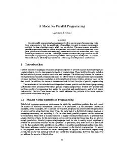
PolyBot [12] is a chain-type modular reconfigurable robot. Three successive generations of PolyBot have been developed at the Palo Alto Research Center, more than 100 modules have been built and various locomotion gaits have been demonstrated. Locomotion gaits are scalable, if the size of programs does not grow with the number of modules. In this paper, we present a formal programming model, Phase Automata, for designing scalable locomotion gaits for this type of system. A phase automaton is an event-driven state automaton with an initial phase delay. The phase delay is normally a real value between 0 and 1. Phase automata are compact representations of locomotion gaits and capable of being embedded and distributed across modules. The concepts of phase automata have been implemented on both PCs and embedded micro-processors. An XML script language and programming interface for phase automata are being built. Locomotion gaits designed in Phase Automata have been tested both in simulation with 100+ modules and in hardware with 50+ modules. Fig. 1 is a configuration of a 14-leg centipede composed of 55 modules.
Fig.1. A 14-leg centipede with 55 modules
The rest of the paper is organized as follows: Section II briefly presents the electro-mechanical design of PolyBot, and its control and communication functionality. Section III introduces Phase Automata, a formal model for gait programming. Section IV describes the use of Phase Automata for the design of three scalable gaits for scalable configurations, and for sensor-driven gaits such as a conforming loop.
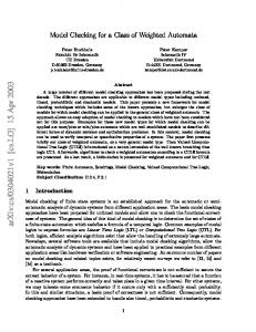
II. POLYBOT: ELECTRO-MECHANICAL DESIGN Three distinct generations and numerous variations of PolyBot have been designed. Most designs consist of two types of modules: a segment is a one-degree of freedom module with two connection interfaces and a node is a rigid cube with four or six connection interfaces. All the connection interfaces are identical and a pair can be connected in any one of four possible orientations (Fig. 2).
passed from module to module. Each connection plate has IR photo transistors and IR LEDs. Combinations of IR intensity measurements allow the determination of the relative 6 DOF position and orientation of mating plates. This aids in the closed loop docking of two modules and their connection plates [5,17]. Each module communicates over a global CAN bus with up to 1M bps. Software architecture for G3 features three layers of communications [15,16,18] with powerful embedded computation. The PolyBot systems have demonstrated versatility by showing multiple modes of locomotion and self-reconfiguration. PolyBot modules can be connected in various forms, from simple ones such as linear connections (snakes), loops, to legged creatures (Fig. 1) and humanoids (Fig. 4).
Fig.2 Two types of PolyBot modules: left, segment, right, node
The first generation (G1) of PolyBot was by far the most prolific, both in terms of different versions created, and the number of modules actually created in each batch. All members of this family are characterized by their use of commercial off the shelf (COTS) motors with integrated controllers (“hobby servos”) and laser-cut plastic. A total of 120 G1v5 modules (Fig. 3) have been built recently, with improved overall robustness and a choice of battery power or plug-in DC-DC converter for running off a high voltage extend powered bus.
Fig 4. A 15 module humanoid
Each segment can be controlled to be in one of the following states: (1) moving in constant speed or move to a desired angle within certain time, (2) freeze, and (3) slack. In addition to local sensors such as joint angle sensors and touch sensors, global sensors such as accelerometers and cameras can also be incorporated. III. PHASE AUTOMATA: MODEL AND DESIGN
Fig.3 G1v5 PolyBot segment and chain
G1 modules are simple and robust, but require manual reconfiguration and on-board processing is limited, and there is no communication between modules. Computation typically takes place in a host and communication amongst the host and modules is via a serial bus. Generations two (G2) and three (G3) have more sensors (including the IR range sensor), the latch mechanisms (which enables self-docking), powerful on-board computation and communication. Both G2 and G3 use a Motorola PowerPC MPC555 embedded processor with 448K internal flash ROM and 1M of external RAM [12]. The connection plate serves two purposes: to attach two modules physically together as well as electrically; both power and communications are
A traditional way of programming locomotion gaits for modular robots is using of gait tables [11,12,14]. A gait table is a two-dimensional array, with one axis representing modules, and the other representing time; the entries of the table are joint angles. Gait tables are simple and easy to handle, however the size of the gait tables grow linearly with increasing number of modules. From software point of view, this is not scalable. There are two properties of locomotion gaits that may be exploited. Firstly, most locomotion gaits are periodic. Those gaits with irregular intervals are the result of being sensor (environment)-driven instead of time-driven. Secondly, the behavior of a module (or a group of modules) as a function of time is usually the same for all modules (or all groups), bar a phase shift. Phase Automata is developed as a formal and compact model for programming locomotion gaits for modular robots.
0.5T
A. Phase Automata Model A Phase Automaton is a regular event-driven state machine [1] augmented with an initial phase delay - a real value between 0 and 1. A phase automaton may or may not have finite states; however the transition from one state to another is discrete, driven by events. A phase automaton can be associated with a set of events, which can be timers or conditional sensory triggers. Different types of events may result different actions and state transitions. Formally, a phase automaton is a tuple PA = (St, Sr, E, A, f, s0, δ) where: • St: a set of states. A state can be one value, a vector or a structure of data, internal to the automaton; • Sr: a set of sensor readings. A sensor can be logical or physical, such as a clock, a joint angle reading or a bumper, etc; • E: a set of events as function of sensor readings e: Sr → {0, 1}. A simple event is a timer. Sensordriven events can be defined in general; • A: a set of actions. An action can be logical or physical, e.g. moving or stopping a joint, or changing parameters for control; • f: a state transition function St x Sr x E → St x A, the transition is triggered by one of the events; • s0: an initial state for the automaton; • δ: an initial phase delay with respect to the initial state, which is a real value, generally between 0 and 1. For periodic gaits, it indicates a phase shift of the whole periodic cycle. For non-periodic gaits, it indicates initial delay with respect to the total time. A phase automaton has its own thread of control, which can be started, stopped, suspended or resumed by an external command, just like any thread. The continuous phase delay makes a compact representation for various phase shifts among modules. For example, a two state automaton with 0.25k (k=0,1,2,3) shift has to be represented by four states in regular automaton (Fig. 5).
t
t
Fig.5 A phase delay of 0.25 for a two-state (0, 1) automaton
A phase automaton can be represented graphically with states as vertices and transitions as arcs between vertices, labeled by event triggers, sensors and actions. The initial state is marked by an arrow pointing to it, labeled by initial phase delay. For example, the automaton at the right of Fig. 5 can be represented in Fig. 6.
1
0 0.5T 0.25
Fig.6.A graphical representation of a two-state (0, 1) automaton with phase delay of 0.25, where T is the total cycle time
A phase automaton can be applied to a group of single modules with different phase shifts, or a group of modules, such as an arm or a leg. Different automata can be applied to different groups of modules, run in serial or in parallel. B. Phase Automata Design The Phase Automata Model is concurrent and distributed in nature. We have implemented the Phase Automaton model on a PC using Java, in which each Phase Automaton is implemented as a single thread. We have also implemented the Phase Automata model on a MPC555, on the top of Attribute/Service Model (ASM) [18]. An XML script language and programming interface are being developed. In this environment, both module configurations and automata are represented by XML scripts. Details of this work shall be described in future papers. IV. SCALABLE LOCOMOTION GAITS We have developed a class of configuration specifications which is scalable; these including three basic types: snakes, centipedes and multi-loops. In this section, we present gaits for this class of configurations using Phase Automata. For gait automata of modular robots, control actions are one of the following: setting a desired joint angle or motor speed, freezing motion, or making the module complying with external forces (slack mode). For most situations, events are timers. Normally transition times between states are relative, and the total cycle time is used for controlling the speed of motion. A. Snake Gait A snake is a linearly connected sequence of modules, with two types of segments: a segment whose rotation axis is parallel to the ground termed a horizontal segment, and whose rotation axis is at right angles to the ground termed a vertical segment. There are two types of automaton for snake locomotion, one is applied to horizontal segments for forward motion, and another is applied to vertical segments for turning motion.
0.5T
Tb -α
+α 0.5T φ
0
β δ
The phase automata can be run independently in each module. The initial phase delays for modules can either be set globally when starting the forward or turning locomotion, or else determined locally if each module knows its position in the chain.
Ts
Fig.7 . Left: forward; Right: turning, for snake locomotion
The forward motion automaton (Fig. 7 left) has two states: one for a positive angle and one for a negative angle. The transition between the two states is triggered by time. Let the total cycle time be T, the transition time is 0.5T. The initial phase delay φ varies from segment to segment, and is determined by the position of the horizontal segment in the chain. The difference in phase delay ∆φ between any two neighboring horizontal segments is a constant. Fig. 8 shows a chain of 12 horizontal segments with α = 0.25 and ∆φ = 0.125. The parameters α and ∆φ control the shape of the snake. If ∆φ is less than 0.5, the amplitude of the snake’s wave is proportional to sinα/∆φ and the width of the wave is proportional to cosα/∆φ, for small values of α.
B. Loop Gait When the two ends of a snake are connected, it becomes a loop. Loop locomotion is one of the most efficient motions on flat surfaces. The forward motion loop automaton applies to the horizontal segments in a loop and in general has five state transitions (Fig. 10): T1, head strengthen; T2, tail bending; T3, tail strengthen; T4, head relaxing; T5, head bending. The transitions between states are time-driven. The phase delay between neighboring horizontal segments is 1/N where N is the total number of horizontal modules. Given that T is the total cycle time for a loop, then the transition times T1 = T3 = (π/α)T/N, T2 = (1/2)T- (π/α)T/N, and T4+T5 = (1/2)T- (π/α)T/N. The ratio between T4 and T5 can be varied. A number of modules are always maintained in a compliant state to avoid internal conflict due to mechanical error and the over constrained nature of the loop. Here the bending angle α controls the shape of the loop. The loop automaton is independent to the number of horizontal segments N, however, the time transition between states is a function of both α and N.
Fig.8 . A snake of 12 horizontal segments
The turning automaton (Fig. 7 right) has two states: one is for bending to β and one for strengthening to 0. The transition between the two states can be triggered by time or sensor signals. Turning can be either periodic or nonperiodic. For non-periodic turning, Ts is infinite. In this case, the phase delay δ is defined to be the ratio between the actual delay of bending and the time of bending Tb for the segment; in which case, δ can be out of (0, 1). Assume that the difference in phase delay between neighboring vertical segments is a constant ∆δ, the radius of the turning, i.e., the number of modules in bending state, is 1/∆δ, and the total turning angle is β/∆δ. Fig. 9 shows two turning actions, one with radius 3 and total turning angle π/2 and the other with radius 4, and total turning angle π/3. Given a required radius R and a total turning angle A, ∆δ and β can be obtained: ∆δ = 1/R; β = A/R. The bending time Tb is related to the forward motion speed; it can also be sensory driven.
~0
T5
T4
0
+α φ
T3 +α
T1
0
T2
. Fig.10 . Forward loop automaton
The time-based loop gait is not robust when traveling across rough terrain. By utilizing sensors that can detect contact with the terrain, a similar gait can be generated that conforms to the terrain (Fig. 11).
Fig.11 . Conforming loop Fig.9 . Turning snake
In this case, a new state is added (Fig. 12). The new state, labeled -0, is no longer time-based. Instead the motor is
actuated, and it continues to slowly unbend until the touch sensor is triggered, causing it to transition to the next state (labeled 0). This same touch also triggers the transition of the first of the modules in the bending state (labeled +α) to the -0 state, and the first of the modules in the relaxed state (labeled ~0) to the bending state. In this case, T2, T3 and T4 are time driven as before, but T1, T5 and T6 are sensor driven, as indicated by the heavy arrows in Fig. 12.
φ
T4
~0
T5
0
T3
+α
+α
T6
-0
T1
0
T2
Fig.12. Conforming loop automaton
C. Centipede Gait Centipedes are the most flexible of the three configurations in the number of possible gaits. A centipede leg automaton applies to a leg, which is composed of a set of segments. A leg automaton in general has four states (Fig. 13). If the cycle time for a leg is T, then T2+T3 = (1-β)T and T4+T1=βT, where β is called duty cycle. Given an N-pair leg centipede, β should be greater than or equal to 3/(2N), to ensure stability. up
φ
T2
down T3
T1 T4 rest
Fig.14 . Two different centipede leg configurations
There are two ways that turning gaits can be implemented. For a centipede with short body length, it is enough to change relative stride sizes of the left and right legs, i.e., for turning left, the stride size for the left legs should be smaller than that for the right legs, and vice versa. For a long centipede, a turning gait for the spine should be applied, similar to a snake’s turning strategy described in Section 4.A. V. CONCLUSIONS We have developed Phase Automata as a way of programming scalable locomotion gaits. This has been demonstrated through the design of locomotion gaits for three types of configuration: snakes, loops and centipedes. Phase automata have been implemented on both PCs and embedded microprocessors. Locomotion gaits using phase automata have been tested in simulation with 100+ modules and in hardware with 50+ modules.
reset VI. ACKNOWLEDGEMENT
Fig.13. Leg automaton
The step height and stride size are other parameters that can be set. While general inverse kinematics routines can be applied to legs, this is not efficient. Rather, three active joints are selected and a closed form solution is obtained. The selection of joints, called leg configuration, results in different gait properties. Fig. 14 shows two different leg configurations for the same centipede: the left (horizontal configuration), is wider and lower, increasing stability and speed, and the right (vertical configuration), is thinner and taller, requiring lower torques to legs. Centipede gaits also vary in terms of different phase delay between legs. In general, the left and right legs of a pair for an N-pair leg centipede always have 0.5 phase difference. Let the left legs be numbered in 2i, and right legs be numbered as 2i+1, for i=0,…,n-1. The variations of this gait (based upon the phase) have been particularly studied [7]: • • •
In all cases: φ[2i+1] = F(0.5+ φ[2i]), where F(x) is a fractional part of a real number x.
wave: φ[2i] = F(iβ); equal phase: φ[2i] = 1 – i/N; half equal phase: φ[2i] = 1 – i/(2N);
This work is funded in part by the Defense Advanced Research Project Agency (DARPA) contract #MDA972-98C-0009. VII. REFERENCES [1] C.G. Cassandras and S. Lafortune, Introduction to Discrete Event Systems, Kluwer Academic Publishers, 1999. [2] T. Fukuda, S. Nakagawa, “Dynamically Reconfigurable Robotic System,” Proc. of the IEEE Int. Conf. on Robotics and Automation, 1988, pp. 1581-1586. [3] S. Murata, H. Kurokawa, E. Yoshida, K. Tomita, S. Kokaji, “A 3D Self-Reconfigurable Structure,” Proc. of the IEEE International Conf. on Robotics and Automation, May 1998, pp. 432-439. [4] A. Pamecha, C. Chiang, D. Stein, G.S. Chirikjian, “Design and Implementation of Metamorphic Robots,” Proc. of the 1996 ASME Design Engineering Technical Conf. and Computers in Engineering Conf., Irvine, California, August 1996.
[5] K. Roufas, Y. Zhang, D. Duff, M. Yim, “Six Degree of Freedom Sensing for Docking using IR LED Emitters and Receivers,” Seventh International Symposium on Experimental Robots, Dec. 2000. [6] D. Rus, M. Vona, “Self-reconfiguration Planning with Compressible Unit Modules,” Proc. of the IEEE International Conf. on Robotics and Automation, pp2513-2520, May 1999. [7] S.M. Song and K.J. Waldron, Machines that Walk: The Adaptive Suspension Vehicle, the MIT Press, 1989. [8] K. Tomita et al, “Development of a Self-Reconfigurable Modular Robotic System,” Proc. of SPIE Sensor Fusion and Decentralized Control in Robotic Systems III, Vol. 4196. [9] C. Unsal , P.K. Khosla, “Solutions for 3-D Selfreconfiguration in a Modular Robotic System: Implementation and Path Planning,” Proc. of SPIE Sensor Fusion and Decentralized Control in Robotic Systems III, Vol. 4196. [10] P. Will, A. Castano, W-M Shen, “Robot modularity for self-reconfiguration,” SPIE Intl. Symposium on Intelligent Sys. and Advanced Manufacturing, Proceeding Vol. 3839, Sept. 1999, pp. 236-245. [11] M. Yim, “New Locomotion Gaits,” Proc. of the IEEE International Conf. on Robotics and Automation, May 1994, pp. 2508-2514. [12] M. Yim, D. Duff, K. Roufas, “PolyBot: a Modular Reconfigurable Robot” Proc. of the IEEE Int. Conf. on Robotics and Automation, April 2000. [13] M. Yim, Y. Zhang, J. Lamping, E. Mao, “Distributed Control for 3D Metamorphosis,” Autonomous Robots 10, special issue on self-reconfigurable robots, 2001, pp. 41-56. [14] M. Yim, Y. Zhang, D. Duff: “Modular Robots”, Cover Story on February 2002 issue of IEEE Spectrum Magazine. [15] Y. Zhang, K. Roufas, M. Yim, "Software Architecture for Modular Self-Reconfigurable Robots", IEEE/RSJ Intl. Conf. on Intelligent Robots and Systems (IROS), Hawaii, USA, Oct. 2001. [16] Y. Zhang, K. Roufas, M. Yim, C. Eldershaw, “Massively Distributed Control Nets for Modular SelfReconfigurable Robots”, 2002 AAAI Spring Symposium on Intelligent Distributed and Embedded Systems. [17] Y. Zhang, K. Roufas, C. Eldershaw, M. Yim, D. Duff, "Sensor Computation in Modular Self-Reconfigurable Robots", Experimental Robotics VIII, Advanced Robotics Series, Bruno Siciliano Ed. Springer, 2003. [18] Y. Zhang, M. Yim, K. Roufas, C. Eldershaw, D. Duff , "Attribute/Service Model: Design Patterns for Efficient Coordination of Distributed Sensors, Actuators and Tasks in Embedded Systems", Workshop on Embedded System Codesigns, 2002.