Abstract. A technique for extracting intrinsic images, including the reflectance and illumination images, from a single color image is presented. The technique first ...
Physics-based Extraction of Intrinsic Images from a Single Image Yun-Chung Chung, Jung-Ming Wang, Robert R. Bailey, Sei-Wang Chen Graduate Institute of Computer Science and Information Engineering National Taiwan Normal University, Taiwan, R.O.C.
Shyang-Lih Chang
Shen Cherng
Department of Electronic Engineering St. John's & St. Mary's Institute of Technology
Department of Electrical Engineering Cheng Shin University, Taiwan
Abstract A technique for extracting intrinsic images, including the reflectance and illumination images, from a single color image is presented. The technique first convolves the input image with a prescribed set of derivative filters. The pixels of filtered images are then classified into reflectance-related or illumination-related based on a set of chromatic characteristics of pixels calculated from the input image. Chromatic characteristics of pixels are defined by a photometric reflectance model based on the Kubelka-Munk color theory. From the classification results of the filtered images, the intrinsic images of the input image can be computed. Real images have been utilized in our experiments. The results have indicated that the proposed technique can effectively extract the intrinsic images from a single image.
process to categorize pixels of filtered images as being reflectance-related or illumination-related. Their method took about 6 minutes to classify pixels and took another 6 minutes to perform an evidence propagation process to improve the result. Clearly, this is not adequate for realtime applications. Matsushita et al. [7] incorporated an illumination eigenspace in Weiss’ framework. The eigenspace provides a priori information which enables their process to quickly derive the intrinsic images from a single image. To generate the eigenspace, they used a set of 2048 images collected over a period of 120 days. In this paper, we propose an effective technique to quickly extract intrinsic images from a single image. The proposed approach is described in section 2. Major steps involved in the approach are detailed in sections 3 to 5. Experimental results are presented in section 6, and followed by concluding remarks / future work in section 7.
1. Introduction
2. Intrinsic Image Extraction
Extracting intrinsic characteristics (e.g., reflectance and illumination) from images is desirable for many objectives, such as shading analysis [6], illumination assessment [7] and shadow removal [4], which in turn are useful for various vision applications, such as face recognition [6], vehicle detection and classification, traffic monitoring, and security surveillance [7]. Extraction of intrinsic images from input images is a nontrivial task. An early work by Barrow and Tenenbaum [2] modeled an image I as the product of a reflectance component R and an illumination component L, i.e., I = R × L. To decompose R and L from I is an ill-posed problem because two unknowns (R, L) are to be derived from a single I. Recently, Weiss [8] solved this problem using an assumption that the convolutions of images and derivative filters tend to be sparse. Consider a scene with reflectance R. Let Ii (i = 1,..., n) be a collection of images acquired from the scene with possibly different illuminations, from which a set of n equations, Ii = R × Li (i = 1,..., n), can be obtained. This set of equations is still not enough to solve for the n+1 unknowns of R and Li. Additional constraints need to be included. Weiss introduced the sparseness assumption and successfully recovered R and Li from n input images using maximum-likelihood estimation. Since multiple images were used by Weiss, the applicability of his method is restricted. Tappen et al. [5] proposed a technique to recover intrinsic images from a single image. In their work, a classifier was introduced into Weiss’
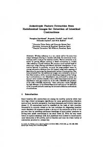
Fig. 1 is a flowchart for the proposed technique. I denotes the input image, which is modeled as I = R ͪ L, where R (reflectance) and L (illumination) are the intrinsic images of I and are to be extracted. We first calculate certain chromatic characteristics of pixels in I. Next, the input image is transformed into the log domain, i.e., I’ = log I = log (R ͪ L) = log R + log L = R’ + L’. The log I image I’ is then convolved with a prescribed set of derivative filters, fj (j = 1,…, n), giving a set of filtered images I’j = I’ * fj. The pixels of the filtered images are then classified as being reflectance-related or illumination-related based on the chromatic characteristics of pixels pre-calculated from I. The resulting images are further improved using an evidence following procedure. Each classified image is separated into a reflectance-related image Rˆ ′j and an illumination-related image Lˆ ′j . Based on these images, we ˆ and the illumination estimate the reflectance image R′ ˆ ˆ and L′ ˆ image L′ of the transformed image I'. Finally, R′ are returned to the linear pixel value domain (i.e., using the anti-log) to obtain the intrinsic images Rˆ and Lˆ of the input image I.
3. Chromatic Characteristics of Image Pixels Certain chromatic characteristics of pixels are calculated from the input image and are used to classify the pixels of
Proceedings of the 17th International Conference on Pattern Recognition (ICPR’04) 1051-4651/04 $ 20.00 IEEE
the filtered images into reflectance-related or illuminationrelated pixels. The chromatic characteristics are defined by a photometric reflectance model [3] rooted in the KubelkaMunk theory. Assume the materials being observed are opaque, i.e., not transparent or translucent. The photometric G reflectance model, denoted by E (λ , x ) , describes the optical properties of mediums regarding the absorption and scattering of light, and is G G G G G G E (λ , x ) = e(λ , x )(1 − ρ f ( x ))2 R∞ (λ , x ) + e(λ , x ) ρ f ( x ) , (1)
G where x is the location of a pixel, λ is the wavelength, G G e(λ , x ) is the illumination spectrum, ρ j ( x ) is the Fresnel
G reflectance, and R∞ (λ , x ) is the material reflectivity. Since there are many factors that can influence the imaging condition, such as spectrally uniform or non-uniform illumination, matte or shiny surfaces, and singly or multiply colored objects, different chromatic characteristics can be derived for image pixels under different imaging conditions. For the condition of spectrally uniform illumination in which the spectral components of the light source are constant over the relevant wavelengths, Eq.(1) simplifies to (2) E (λ , x) = i ( x) {(1 − ρ f ( x))2 R∞ (λ , x ) + ρ f ( x)} , where i(x) is the intensity variation originating from the object geometry. In the following equations the λ subscripts denote partial derivatives. Furthermore, if an object has reflectance property, H, which is independent of surface orientation, viewpoint, illumination direction and density, then the reflectance property of the object can be described by H λm =
∂m ∂λ m
where Eλ = Eλλ =
−1 Eλ ½ , )¾ ® tan ( Eλλ ¿ ¯
(3)
∂R (λ , x) ∂E (λ , x) = i ( x) (1 − ρ f ( x)) 2 ∞ , and ∂λ ∂λ
∂λ 2 E (λ , x) ∂λ 2
= i ( x) (1 − ρ f ( x)) 2
∂ 2 R∞ (λ , x) ∂λ 2
.
Hλm
§ ∂R∞ (λ , x) · ½ °° ¨ ¸ °° −1 ∂λ ¸¾. ® tan ¨ 2 ¨ ∂ R∞ (λ , x) ¸ ° ° ¨ ¸ ∂ 2λ © ¹ ¿° ¯°
Cλ m
(7)
Finally, if the object surface is planar (i.e., a Mondrian world), equation (5) becomes (8) E (λ , x) = iR∞ (λ , x) . The object reflectance property, W, can be specified by
Wλ m =
Eλ m x E
.
(9)
From Eq. (8), ∂ m ∂R∞ (λ , x ) ∂ m ∂R∞ (λ , x ) i ∂ m λ∂x ∂ m λ∂x . (10) = Wλ m = iR∞ (λ , x) R∞ (λ , x) W is a geometry dependent intensity term and can be viewed as an edge detector in some spectral distribution. Next, for colored and non-uniform illumination and objects with matte surfaces, equation (1) can be written as (11) E (λ , x) = e(λ )i ( x ) R∞ (λ , x ) , where e(λ) represents the illumination spectrum. In this case, if the reflectance property is independent of surface orientation, viewpoint, illumination direction, density and color, then the change N in object reflectance is defined as ∂ m −1 E E − E E ½ (12) N λ m = m−1 ® λ x 2 λ x ¾ . E ∂λ ¯ ¿ Furthermore, if an object has a uniformly colored planar surface, its reflectance property is spatially constant, and equation (1) can be written as (13) E (λ , x) = e(λ , x) {(1 − ρ f ) 2 R∞ (λ ) + ρ f } . The object spectral reflectance, Uλ, is E E−E E (14) Uλ = λx 2 λ x , E which is actually a special case of N. In this study, the set of chromatic characteristics of image pixels, S = {H λ m , Cλ m ,Wλ m , N λ m , U λ } , are used to classify the pixels of filtered images as being reflectancerelated or illumination-related.
Therefore, ∂m = m ∂λ
∂ m R∞ (λ , x) ∂ m R∞ (λ , x) , ∂ mλ ∂mλ = = i( x) R∞ (λ , x ) R∞ (λ , x) i ( x)
(4)
Equation (4) states that H depends only on the object reflectivity R∞(λ, x). Moreover, if the constraint of matte surfaces is also included, in which the Fresnel reflectance is G very small, i.e., ρf(x) tmax and cmin > tmin, rp = false, if cmax < tmax and cmin < tmin,
Proceedings of the 17th International Conference on Pattern Recognition (ICPR’04) 1051-4651/04 $ 20.00 IEEE
rp = unknown, otherwise, (15) where tmax and tmin are thresholds. A reflectance-related image Rˆ ' j is then formed by the pixels {p∈I’j | rp = true} and an illumination-related filtered image Lˆ ' j is formed by the pixels {p∈I’j | rp =
false}. Pixels whose rp’s are unknown are classified as follows. Suppose that pixel q has not been classified. Among its neighbors that have been classified, we find the one with the largest filtered value and regard q as being in the same class as that neighbor.
5. Estimation of Intrinsic Characteristics
[-1 0 1]T. The pixels of the filtered images are then classified based on 10 chromatic characteristics of image pixels pre-calculated from the input image, H, Hλ, Hλλ, Cλ, Cλλ, W, Wλ, Wλλ, Nλ, and Nλλ. To calculate these values, we first compute E, Eλ and Eλλ following [3] (21) ª Eˆ º −0.48 1.2 0.28 X ª « » « « Eˆλ » = « 0.48 « ˆ » « 1.18 «¬ Eλλ »¼ ¬
, where [X, Y, Z]T is the basis of the CIE 1964 XYZ color model. Assume that the camera response is linear. [X, Y, Z] values can then be estimated from [R, G, B] values by ª Xˆ º ª 0.62 0.11 0.19 º ª R º (22) « » « »« » « Yˆ » = « 0.3 0.56 0.05» «G » « ˆ » « −0.01 0.03 1.11 » « B » ¼¬ ¼ ¬« Z ¼» ¬
ˆ for each filtered image I’j Having determined Rˆ ′j and L′
. Substituting Eq. (21) into Eq. (22) gives
(j=1,…,n), we can now estimate the reflectance image Rˆ and illumination image Lˆ . Following Weiss [8], n
Rˆ ' = g *(¦ j =1
n
f * Rˆ ' j ) , Lˆ ' = g *(¦ f jr * Lˆ ' j ) , r j
¦
j
j =1
j
j =1
Since convolution is associative and commutative, n
convolving both sides of Eq. (17) with
¦ f j' ∗ f j gives j =1
n
n
j =1
j =1
n
(¦ f jr * f j ) * Rˆ ' = ((¦ f jr * f j ) * g ) *(¦ f jr * Rˆ j ) j =1
n
n
j =1
j =1
(18)
= δ *(¦ f jr * Rˆ j ) = ¦ f jr * Rˆ j .
Let F (F–1) denote the (inverse) Fourier transform. Applying the Fourier transform to Eq. (18), n
n
j =1
j =1
F ((¦ f jr * f j ) * Rˆ ') = F (¦ f jr * Rˆ j )
.
(19)
From the convolution theorem, n
n
F (¦ f jr * f j ) F ( Rˆ ') = F (¦ f jr * Rˆ j ) , j =1
j =1
n
F ( Rˆ ') =
F (¦ j =1 n
ª Eˆ º ª0.06 0.63 0.27 º ª R º « » « »« » « Eˆ λ » = « 0.3 0.04 −0.35» «G » « ˆ » «0.34 −0.6 0.17 » « B » E ¼¬ ¼ ¬« λλ ¼» ¬ .
(16)
where fjr is the reversed filter function of fj, defined as fjr(x, y) = fj(-x, -y), and x, y are pixel coordinates. The symbol * denotes discrete convolution, and g here is a normalization function, which is the solution to the following equation (δ is the Kronecker delta function): n (17) g *( f r * f ) = δ
n
f * Rˆ j ) r j
, Rˆ ' = F −1 (
F (¦ f jr * f j ) j =1
F (¦ f jr * Rˆ j ) j =1 n
(20) )
F (¦ f jr * f j ) j =1
Then Rˆ = exp( Rˆ '), and Lˆ can be found by Lˆ = I / Rˆ .
6. Experimental Results During experiment, each input image is first transformed into the log domain. The transformed image is filtered with two derivative filters, a horizontal and a vertical Prewitt filter, specifically f1 = [-1 0 1] and f2 =
ºª º −0.4 »» «« Y »» 0 ¼» ¬« Z ¼» −1.3 0
(23)
Using Eqs. (3), (6), (9), and (12) we compute H, Hλ, Hλλ, Cλ, Cλλ, W, Wλ, Wλλ, Nλ, and Nλλ. Figures 2 to 5 show some experimental results. In each figure, the first picture is the input image, which is an RGB color image with a size of 320 by 240 pixels. The intrinsic images (reflectance and illumination) extracted from the input image are the second and third pictures, respectively. Our program is written in the C language and runs on a 2.4 GHz Pentium PC. The program took about 5 sec. to decompose an input image into its reflectance and illumination images. We have observed that most of the processing time is consumed by the FFT computations, even though we use MIT’s FFTW package [1], which is considered to be the fastest available. Figures 2 and 3 show two outdoor examples. The input images (a) contain many shadows cast by objects due to sunshine. In the decomposed reflectance images (b), both shadows and sunshine have been successfully eliminated. However, objects can still be seen in the illumination images (c). Matsushita et al. claimed in their work that objects should be invisible in illumination images. We cannot agree because the illumination close to object surfaces is influenced by their colors. The appearance of faint object shapes in the illumination images can be acceptable. Figure 4 shows an experiment of a vehicle license plate image, where some small object casts a shadow on part of the license plate. Such shadows have sometimes annoyed our license plate recognition (LPR) process. This problem has been reduced by applying our LPR process to reflectance images. Figure 5 shows an indoor example. The input image was taken in a cave with dim lighting. In the cave are many statues with black surfaces. Although color evidence seems no long significant, the decomposed reflectance image shown in Figure 5(b) possesses a better visibility than the original image. This example implies that
Proceedings of the 17th International Conference on Pattern Recognition (ICPR’04) 1051-4651/04 $ 20.00 IEEE
the proposed set of chromatic characteristics consists of achromatic ones too.
7. Concluding Remarks and Future Work A physics-based approach based on the Weiss framework for extracting intrinsic images from a single image was presented. The proposed technique relies on a set of chromatic characteristics defined by a photometric reflectance model rooted in the Kubelka-Munk theory. This set of chromatic characteristics has played an important role in effectively classifying the pixels of filtered images as being reflectance-related or illumina-tion-related. Moreover, the chromatic values of image pixels are easily calculated from the input image. The current program took a few seconds to extract intrinsic images from a single image. However, for realtime applications the processing time should be reduced. We have observed that most of the processing time is consumed by a number of FFT computations involved in the process, even though the fastest FFT routines that we know of is already employed in our implementation. Reducing the number of FFTs will be an important direction in our future work. In addition, more investigations into the physical meanings of the chromatic characteristics will be necessary in order to improve the classification results of filtered image pixels.
References [1] FFTW package, developed at MIT by Matteo Frigo and Steven G. Johnson, http://www.fftw.org/ [2] H.G. Barrow, and J.M. Tenenbaum, “Recovering intrinsic scene characteristics from images”, in A.R. Hanson and E.M. Riseman (Eds.), Computer Vision Systems, Academic Press, pp. 3–26, 1978. [3] J.M. Geusebroek, R. van den Boomgaard, A.W.M. Smeulders, and H. Geerts, “Color invariance”, IEEE Trans. on PAMI, Vol. 23, Issue. 12, pp.1338-1350, 2001. [4] J.M. Wang, Y.C. Chung, S.L. Chang, and S. W. Chen, “Shadow Detection and Removal for Traffic images,” IEEE International Conf. on Networking, Sensing and Control, Taipei, Taiwan, Mar 2004. [5] M.F. Tappen, W.T. Freeman, and E.H. Adelson, “Recovering Intrinsic Images from a Single Image”, Proc. of Neural Information Processing Systems, 2002. [6] S.G. Shan, W. Gao, B. Cao, and D. Zhao, “Illumination normalization for robust face recognition against varying lighting conditions”, IEEE Intel. Workshop on Analysis and Modeling of Faces and Gestures, pp. 157 -164, 2003. [7] Y. Matsushita, K. Nishino, K. Ikeuchi, and M. Sakauchi, “Illumination normalization with time-dependent intrinsic images for video surveillance”, IEEE C.S. Conf. on Computer Vision and Pattern Recognition, Vol. 1, pp.I-3-10, 2003. [8] Y. Weiss, “Deriving intrinsic images from image sequences”, IEEE Intel. Conf. on Computer Vision, Vol. 2, pp.68-75, 2001.
(a) (b) Figure 2. The intrinsic images from a single image, (a) input image I, (b) reflectance image Rˆ , (c) illumination image Lˆ .
(c)
(a)
(a) (b) (c) Figure 3. The intrinsic images from a single image, (a) input image I, (b) reflectance image Rˆ , (c) illumination image Lˆ .
(b)
(c) Figure 5. The intrinsic images from a single (a) (b) (c) image, (a) input image Figure 4. The intrinsic images from a single image, (a) input I, (b) reflectance image I, (b) reflectance image Rˆ , (c) illumination image Lˆ . image Rˆ , (c) Figure 1. Flowchart of physics-based extraction illumination image Lˆ . of intrinsic images from a single image.
Proceedings of the 17th International Conference on Pattern Recognition (ICPR’04) 1051-4651/04 $ 20.00 IEEE