ISSN 2319-8885 Vol.03,Issue.13 June-2014, Pages:2924-2929 www.semargroup.org, www.ijsetr.com
PID Controller Tuning using Ziegler-Nichols Method for Speed Control of DC Motor MANOJ KUSHWAH1, ASHISH PATRA2 1
Dept of Electrical Engineering, Madhav Institute of Technology and Science, Gwalior, India, E-mail:
[email protected]. 2 Dept of Electrical Engineering, Madhav Institute of Technology and Science, Gwalior, India, E-mail:
[email protected].
Abstract: In this paper, a weighted tuning methods of a PID speed controller for separately excited Direct current motor is presented, based on Empirical Ziegler-Nichols tuning formula and modified Ziegler-Nichol PID tuning formula. Both these methods are compared on the basis of output response, minimum settling time, and minimum overshoot for speed demand application of DC motor. Computer simulation shows that the performance of PID controller using Modified Ziegler-Nichols technique is better than that of traditional Ziegler-Nichols technique. Keywords: Ziegler-Nichols Tuning, Modified Ziegler-Nichols Tuning, Optimal Control, PID Controller, DC Motor. I. INTRODUCTION Inspire of the development of power electronics resources, the direct current machine became more and more useful this Nowadays their uses isn't limited in the car applications (electrics vehicle), in applications of weak power using battery system (motor of toy) or for the electric traction in the multimachine systems too. The speed of DC motor can be adjusted to a great extent as to provide controllability easy and high performance [4]-[6]. The controllers of the speed that are conceived for goal to control the speed of DC motor to execute one variety of tasks, is of several conventional and numeric controller types, the controllers can be: PID Controller, Fuzzy Logic Controller, Genetic Algorithm technique, Particle Swarm Optimization technique or the combination between them: Fuzzy-Neural Networks, FuzzyGenetic Algorithm, Fuzzy- Ants Colony, Fuzzy-Swarm. In 1942, Ziegler-Nichols presented a tuning formula [1, 3, 7], based on time response and experiences. Although it lacks selection of parameters and has an excessive overshoot in time response, still opens the way of tuning parameters. Modified Ziegler-Nichols tuning based on Chien-Hrones-Reswick (CRR) PID tuning formula [3, 8] for set-point regulation accommodate the response speed an d overshoot. In this paper, an optimal PID controller for DC motor speed control is developed using Ziegler Nichols (ZN) and Modified Ziegler-Nichols .The performance measure to be minimized contains the following objectives of the PID controller, that will be studied separately, Minimize the rise time, time required for system response to rise from 10% to 90% (over damped); 5% to 95%; 0% to 100% (Under damped) of the final steady state value of the desired response, Minimize the maximum overshoot, Maximum overshoot is the maximum
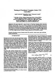
peak value of the response curve measured from the desired response of the system and Minimize the settling time, Time required for response to reach and stay within 2% of final value. II. DC MOTOR MATHEMATICAL MODEL This DC motor system is a separately excited DC motor [7], which is often used to the velocity tuning and the position adjustment. This paper focuses on the study of DC motor linear speed control, therefore, the separately excited DC motor is adopted. Make use of the armature voltage control method to control the DC motor velocity, the armature voltage controls the distinguishing feature of method as the flux fixed, is also a field current fixedly. The control equivalent circuit of the DC motor by the armature voltage control method is shown in Fig.1.
Ra
La if
+ ea
ia
+
K
eb
M K
-
-
Tm,
,
J B Fig.1 The Equivalent Circuit of DC Motor using the control Armature Voltage Control. Where, Ra: Armature resistance La: Armature inductance
Copyright @ 2014 SEMAR GROUPS TECHNICAL SOCIETY. All rights reserved.
MANOJ KUSHWAH, ASHISH PATRA ia : Armature current reduced number of parameters to be tuned. They provide control signals that are proportional to the error between the if : Field current reference signal and the actual output (proportional action), ea : Input voltage to the integral of the error (integral action), and to the eb : Back electromotive force (EMF) derivative of the error (derivative action), namely Tm : Motor torque w: An angular velocity of rotor J: Rotating inertial measurement of motor bearing (8) Kb : EMF constant Where u(t) and e(t) denote the control and the error signals KT : Torque constant respectively, and Kp, 'Ii and Td are the parameters to be B : Friction constant tuned. The corresponding transfer function is given as Because the back EMF eb is proportional to speed ω directly then, (9) These functions have been enough to the most control (1) processes. Because the structure of PID controller is simple, Making use of the KCL voltage law can get it is the most extensive control method to be used in industry so far. The PID controller is mainly to adjust an appropriate proportional gain ( K p ), integral gain (K [ ), and differential (2) gain (KD) to achieve the optimal control performance. The From Newton law, the motor torque can be obtained as PID controller system block diagram of this paper is shown in Fig.3. Kp
(3) Take, (1), (2), and (3) in to Laplace transform, respectively, the equation can be formulated as (4)
e(t)
K1/S
E(S)
Fig.2 describes the DC motor armature control system Function block diagram from equations (1) to (6). + Ea(s) 1/La+Ra KT Tm(s) 1/JS+B Ia(s) (s)
u(t) U(s)
+
(5) (6)
+
+ KDS
Fig.3. PID Controller Block Diagram. Transfer function can also be expressed as
(10) The main features of PID controllers are the capacity to eliminate steady-state error of the response to a step reference signal (because of integral action) and the ability to anticipate output changes (when derivative action is employed).
-
Eb(s)
Kb
Fig.2. DC Motor Armature Voltage Control System Function Block diagram. The transfer function of DC motor speed with respect to the input voltage can be written as follows,
IV. ZIEGLER-NICHOLS TUNING A. Traditional Method This method is applied to plants with step responses of the form displayed in Fig.4. This type of response is typical of a first order system with transportation delay. The response is characterized by two parameters, L the delay time and T the time constant. These are found by drawing a tangent to the step response at its point of inflection and noting its intersections with the time axis and the steady state value. The plant model is therefore (11)
(7) III. PID CONTROLLER Proportional-integral-derivative (PID) controllers [1][3] are widely used in industrial control systems because of the
Ziegler and Nichols derived the following control parameters based on this model.
International Journal of Scientific Engineering and Technology Research Volume.03, IssueNo.13, June-2014, Pages: 2924-2929
PID Controller Tuning Using Ziegler-Nichols Method for Speed Control of DC Motor A standard test model as considered is taken for study of DC motor with Z-N tuning controller. The test model below shown is completely designed in SISO tool. Fig.5 shows the block diagram of DC motor driving an inertial load. Reference Speed
Actual Speed
PID Controller
DC Motor
+ -
Ziegler-Nichols Tuning Algorithm
Fig.4. Response Curve for Ziegler-Nichols Method. In real-time process control systems, a large variety of plants can be approximately modeled by (11). If the system model cannot be physically derived, experiments can be performed to extract the parameters for the approximate model (11). For instance, if the step response of the plant model can be measured through an experiment, the output signal can be recorded as sketched in Fig. 4, from which the parameters of k, L, and T can be extracted by the simple approach shown. More sophisticated curve fitting approaches can also be used. With L and a, the Ziegler-Nichols formula in Table 1 can be used to get the controller parameters.
Fig.5. Block Diagram of DC Motor Control System. From the state equation (refer (1), (2), (3)) previously, we can construct the model with the environment MA TLAB (R201Oa) Simulink. The model of the DC motor in Simulink is shown in Fig.2. The various parameters of the DC motor are shown in Table 3. TABLE III: Dc Motor Parameters
TABLE I: Ziegler-Nichols Tuning First Method
B. Modified Ziegler-Nichols Tuning Method Modified Ziegler-Nichols tuning using ChienHronesReswick (CHR) tuning algorithm emphasizes on setpoint regulation. In addition one qualitative specification on the response speed and overshoot can be accommodated. Compared with the traditional Ziegler-Nichols tuning formula, the CRR method uses the time constant T of the plant explicitly. The CRR PID controller tuning formulas are summarized in Table 2 for set-point regulation.
The system is simulated for the unit step response for various parameter models for different motors as shown in table 3.The Transfer function these three motors are given by following equations. Transfer function for motor 1,
TABLE II: Modified Ziegler-Nichols Tuning Second Method
(12) Transfer function for motor2, (13) Transfer function for motor 3,
Here the parameters k, L, and T are obtained from the response curve of figure 4. With KI=Kp/Ti and KD=Kp*Td. Thus the values of Kp, Ki and Kd are obtain from tables 1 and 2 to form the transfer function for PID controller as given by (9).
(14) A. Traditional Method Flow Chart as shown in fig.6 and 7 is used for MA TLAB coding to find the PID controller parameters and to get DC motor Close loop unit step response of the overall transfer function.
V. SIMULATION AND ANALYSIS International Journal of Scientific Engineering and Technology Research Volume.03, IssueNo.13, June-2014, Pages: 2924-2929
MANOJ KUSHWAH, ASHISH PATRA VI. RESULT AND ANALYSIS
START
Run the DC motor open loop Transfer function for each set of Parameters
Find the open loop step response of gi ven motor Transfer function and Draw the Tangent line of open loop step re 'ponse at Maximum slope
Find L, T Parameters and Calculate Parameters [Kp, Ki and Kd] of PID controller according to Table I
(a)
Find the PID controller Transfer function by equation 9
Finally, Multiply the DC motor and PID controller Transfer function and Find close loop step respons
END
Fig.6. the flow chart of Ziegler- Nichols Tuning method. The controller is connected in cascaded fashion and steresponses for different motors are shown by 8(a), 9(a).
(b) Fig.8. (a) Step response with Traditional Ziegler-Nichols method. (b) Step response with Modified Ziegler-Nicolas method.
B. Modified Ziegler-Nichols Tuning Method
ea
+
wm
ia 1/La
1/s
1/j
Kb
1/s
-
Ra
B
K1
Fig.7. Matlab Simulink Model for Armature Control of (a) DC Motor. International Journal of Scientific Engineering and Technology Research Volume.03, IssueNo.13, June-2014, Pages: 2924-2929
PID Controller Tuning Using Ziegler-Nichols Method for Speed Control of DC Motor VII. ACKNOWLEDGMENT Authors would like to thanks to Dr. Sanjeev Jain, MITS, Gwalior, M.P., to promoting this work.
(b) Fig.9.(a) Step response with Traditional Ziegler-Nichols method. (b) Step response with Modified Ziegler-Nichols method. The step response of DC motor 1 with two methods is show in fig. 8(a) and fig.8(b),the step response of DC motor 2 is shown in the fig.9(a) and fig.9(b) and the step response of DC motor 3 is shown in the fig.9(a) and fig.9(b). From both Modelling and MA TLAB coding a comparison between these two methods have been made on the basis of Objective i.e. Rise time, Overshoot and Settling time as. TABLE IV: Transient Response of Motor 1
TABLE V: Transient Response of Motor 1
TABLE VI: Transient Response of Motor 1
VIII. CONCLUSION In this paper, PID controller is designed using Traditional Ziegler-Nichols and Modified Ziegler-Nichols (CHR) tuning algorithms. The results of both the methods are checked by MA TLAB coding as well as simulation. The speed of a three different DC Motor parameters is controlled by means of these two controllers. According to the results of the computer simulation, the Modified Ziegler-Nichols tuned PID controller efficiently is better than the traditional Ziegler-Nichols. The Modified Ziegler-Nichols is the best controller which presented satisfactory performances for the objectives (i.e Minimum rise time, Minimum overshoot, and Minimum settling time) But, for higher power application DC motors (Motor 1 and Motor 2) and for lower power application motor raditional method found satisfactory IX. REFERENCES [1] K. Astrom and T. Hagglund, PID Controller: Theory, Design and Tuning, 2nd ed, Library of Congress Catalogingin-Publication Data, 1994,pp.120-134. [2] B. C. Kuo, Automatic control system, 7th ed., PrenticeHall of India PVT,2003. [3] D. Xue, Y. Chen and D. P. Atherton, Linear Feedback control, Society of Industrial and Applied Mathematics, 2007, ch. 6. [4] Y. Ma, Y. Liu and C. Wang Elissa, "Design of Parameters Self-tuning Fuzzy PID Control for DC Motor," in FroG. of Second International Conference on Industrial Mechatronics and Automation (ICIMA), vol. 2, pp. 345-348, 2010. [5] K. A. Naik and P. Shrikant, "Stability Enhancement of DC Motor using IMC Tuned PID Controller," (lJAEST) International Journals of Advanced Engg. Science and Technologies, vol. 4, Issue No. I, pp. 092- 096,2011. [6] W. P. Aung, "Analysis on Modeling and Simulink of DC Motor and its Driving System Used for Wheeled Mobile Robot," World Academy of Science, Engineering and Technology 32, pp. 299-306. 2007. [7] G. Haung and S. Lee," PC Based PID speed control of DC motor," in PrOG. of International Conference on Audio, Language and Image Processing (ICALIP-2008), pp. 400407, 2008. [8] 1. G. Ziegler and N. B. Nichols, "Optimum setting for automatic controllers," Trans. ASME, vol. 64, pp. 759-768, 1942. [9] J. C. Basilio and S. R. Matos, "Design of PI and PID Controllers With Transient Performance Specification ", IEEE Trans. Education, vol. 45, Issue No.4, pp. 364370,2002. [10] O. Montiel, R. Sepulveda, P. Melin, O. Castillo, M. A. Porta and 1. M. Meza, "Performance of a Simple Tuned Fuzzy Controller and a PID Controller on a DC Motor," in
International Journal of Scientific Engineering and Technology Research Volume.03, IssueNo.13, June-2014, Pages: 2924-2929
MANOJ KUSHWAH, ASHISH PATRA FrOG. iEEE Symposium on Foundation of Computational Intelligence (FOCI-2007), pp. 531 537,2007. [11] N. Kamaruddin, Z. Janin, Z. Yusuf and M. N. Taib, "PID Controller Tuning for Glycerin Bleaching Process Using Well-Known Tuning Formulas- A Simulation Study," in ProG. of 35th Annual Conference of IEEE on Industrial Electronics (IECON-2009), pp. 1682-1686,200.
International Journal of Scientific Engineering and Technology Research Volume.03, IssueNo.13, June-2014, Pages: 2924-2929