[2]. Damping injection is a physically interpretable imple- mentation of impedance controller that imposes a desired compliance through shaping of the potential ...
2013 American Control Conference (ACC) Washington, DC, USA, June 17-19, 2013
PID Motion Control Tuning Rules in a Damping Injection Framework Tadele Shiferaw Tadele, Theo de Vries, Member, IEEE and Stefano Stramigioli, Senior Member, IEEE
Abstract— This paper presents a general design approach for a performance based tuning of a damping injection framework impedance controller by using insights from PID motion control tuning rules. The damping injection framework impedance controller is suitable for human friendly robots as it enhances safety due to the compliance it introduces and guarantees asymptotic stability because of its passive nature. In order to perform successful manipulation with a damping injection framework controlled robot, a performance based analysis and tuning of the controller is essential. By mapping a performance based frequency domain tuning of PID controllers on the framework, the proposed tuning method attempts to analyze and define controller parameters that yield a desired performance requirement given in terms of the maximum allowed position error. The effectiveness of the proposed guideline is illustrated with simulation and experimental results. Index Terms— PID, damping injection, impedance control, performance, tuning
I. I NTRODUCTION Robotic manipulators are often used in manufacturing industries to perform position based activities, and hence posses motion controllers to achieve their main performance requirement which is accuracy. During operation human users are kept away from the robot by a barrier, and thus a collision is rarely or almost never observed. On the other hand robots that share a workspace with a human operate in an unstructured environment and demand a prioritized safety requirement. In order to enhance safety of such robots, interaction controllers are mainly used to introduce compliant behavior and minimize injuries that might arise due to unexpected collision. Impedance control is a suitable control technique for human friendly robotic manipulators as it enables control of the energy exchange between the robot and the environment. The idea behind impedance control is the physical observation that manipulation is done via energy exchange and that during the energetic interaction two bodies influence each other through a bidirectional signal exchange [1]. This means that during interaction of two bodies, one imposes the force of interaction and the other imposes the velocity, which is the power conjugate of the force. Impedance control regulates the impedance of the manipulator that relates the interaction force and the resulting motion, thereby avoiding the shortcomings of pure position or force control in Robotics This work was supported by funds from the Netherlands Ministry of Economic Affairs under research project Bobbie. The authors are with the Robotics and Mechatronics chair at the Faculty of Electrical Engineering, Mathematics and Computer Science, University of Twente, 7500 AE Enschede, The Netherlands. E-mail: {t.s.tadele, t.j.a.deVries, s.stramigioli}@utwente.nl
978-1-4799-0178-4/$31.00 ©2013 AACC
[2]. Damping injection is a physically interpretable implementation of impedance controller that imposes a desired compliance through shaping of the potential energy and a desired transient behavior and asymptotic stability via damping injection [3]. Industrial robotic manipulators mainly incorporate a highly stiff position controller because they often perform motion based tasks. The most common controller used with these industrial manipulators is a decentralized PID controller which is preferred due to its simplicity and ability to deal with practical issues [4]. Different time domain, frequency domain, heuristic or optimization based techniques were proposed in literature to analyze, design and tune PID controllers [5]. In the frequency domain based approach, the controller is treated as a lead-lag compensator and its parameters are defined as a function of the open loop crossover frequency, which by itself is chosen from performance requirements. Different authors have included time or frequency domain performance specifications while designing controllers for complaint manipulators [6], [7]. A performance based analysis and tuning of the controller parameters is essential for successful manipulation and it is not available in the damping injection framework. This paper presents an approach to fill this gap by mapping the performance based frequency domain PID tuning technique on to the damping injection framework. The main aim of this approach is to identify the controller parameters of the framework that confer with a performance requirement given in terms of a maximum allowed positioning error. The approach presented here is used to tune a controller by compromising the conflicting requirements of motion tracking that demand stiff systems and interaction tasks that need compliant systems. This paper is organized as follows. In sections II and III, the damping injection framework and frequency domain tuning of PID controllers are briefly introduced. Then section IV discusses the mapping of PID tuning rules on the framework and section V presents simulation and experimental results. Finally section VI summarizes the main ideas and presents the conclusions. II. T HE DAMPING I NJECTION C ONCEPT One of the requirements of controllers used in robotics is ensuring asymptotic stability in all situation of contact, no contact or transition moments between the two phases. The damping injection concepts proposed in [3] introduces a controller which satisfies this stability requirement during interaction with any passive environment. This controller belongs to a type of dynamic systems known as passive
4957
systems and such systems are characterized by having a total energy which is less than or equal to the sum of its initial energy and any external energy supplied during interaction. This means passive systems have no internal production of energy, and thus attain equilibrium at the minimum energy state and guarantee Lyapunov stability during interaction with other passive system [8]. Consider a simplified 1-DOF robot modeled as a mass m which is to be moved to a desired position xv . A simple physical controller to achieve this consists of a spring connected between the desired virtual point and the mass. This mass-spring system is marginally stable and will continue to oscillate unless a damper is added to the system. See figure 1. The resulting system resembles a conventional PD controller that guarantees closed loop stability for any positive gains, with the proportional term representing the spring and the derivative term representing the damper. In addition to placing the object at the desired position in a stable way, the value of kc can be adjusted to give the system a desired compliance which will be felt by any interaction with the system.
As seen in Figure 2, the damping injection framework introduces a virtual mass mc and a bridging spring between this virtual mass and the plant. By choosing a very stiff bridging spring (k >> kc ) and a small virtual controller mass (mc > max((mmc ), bm, kc ) and the virtual mass mc 1
(2) (3)
the maximum phase lead introduced by the controller 6 Cmax is a function of parameter β known as tameness factor. 6
β−1 Cmax = arctan( √ ) 2 β
I
The need to avoid deterioration of the lead behavior in the PD controller put a bound τi ≥ 2.τz on the integrator time constant τi and a range 0.7 ≤ ζ ≤ 0.9 on the damping constant of the differentiator ζ. Consequently the bode plot of the PIDF controller will have a higher gain in the low frequency region and a roll-off in the high frequency region. See Figure 5.
τp
Given a PD controller of the form sτz + 1 C(s) = Kp · ( ) sτp + 1
(8)
_ 1 τi
1
τ z
1
τp
(4)
Furthermore, this maximum phase lead 6 Cmax occurs at a frequency w6 Cmax which is logarithmic half way between the location of the zero τ1z and the pole τ1p . See the bode plot of a PD controller at Figure 4. s 1 w6 Cmax = (5) τp · τz Now the tameness factor β can be selected based on any desired phase margin value using equation (4). Given a desired system cross-over frequency wc and a constant tameness factor β, a reasonable design choice would be to tune the PD controller in such a way that the maximum phase lead occurs at this desired system cross-over frequency.
Fig. 5.
Bode plot of a PIDF controller.
Another freedom of choice in motion systems design is the dynamics of the reference motion. For a complete control system shown in Figure 3, the error E(s) is related to the reference motion R(s) by sensitivity function S(s) which is one property of the system. Keeping in mind the low frequency nature of the motion error Em (s) that defines the
4959
performance, its maximum value emax can be approximated as: Em (s) = lim E(s) = lim S(s) · R(s) (9) s→0
s→0
emax ≈
2β 3 s R(s) wc3
(10)
emax ≈
2β ... x max wc3
(11)
Hence the desired cross-over frequency is calculated as a function of the maximum jerk of the reference motion and the maximum allowable motion error as [11] r ... x max wc = 3 2β (12) emax IV. M APPING PID TUNING RULES ON DAMPING I NJECTION F RAMEWORK In order to map PID tuning rules on damping injection framework, a similar design approach of designing the controller as a function of frequency domain parameters is followed. Using a plant modeled as a mass m, the damping injection framework shown in Figure 2 and defined in (1) can be represented in a simplified feedback block diagram as shown in Figure 6.
Fig. 6.
Block diagram representation of damping injection framework.
The block diagram indicates that a damping injection framework constitutes a complex phase-lead compensator C(s) and a setpoint pre-filter F (s). Looking at Figures 4 and 7, it can be seen that the damping injection controller has the same phase-lead frequency response as a PD controller. The frequency which gives the maximum phase lead for the system can be obtained by solving the equation ∂ 6 C(jw) = 0 ∂w
Let us introduce a scaling design parameter A and damping ratio ζ as follows, p m (16) k = Akc ; mc = ; b = 2ζ Kc m A Then substituting these parameters in (15) yields a maximum phase lead frequency given as: r √ kc wm = B (17) m where B=
A2 6
�
(1 + ( A2 ) − 4ζ 2 ) +
q
12A+12 A2
+ (1 +
2 A
− 4ζ 2 )2
6
C(jw)
= tan
= tan−1 (
bw ( kc −m 2) cw
− tan
−1
Now the first step in the controller tuning starts by selecting a damping ratio ζ that satisfies a desired damping behavior. In order to avoid oscillations and achieve a well damped behavior, the damping ratio has to be chosen in the range of ζ = 0.7...1. Then follows the choice of a scaling parameter A based on a desired maximum phase lead φmax in the controller. Taking a constant ζ, the maximum phase lead φmax increases to an asymptote value of 90◦ as the value of A increases. See the bode plot Figure 7. Even though higher value of A yields an increased phase margin, and thus more robust system, it also increases gain in the noise prone high frequency region. Thus is it recommended to select a lower value of A that yields an acceptable phase lead of at least 45◦ . In this approach, the maximum phase lead φmax may not be achieved at the open loop crossover frequency of the system, the frequency at which kC(s) · P (s)k = 1, but the phase lead at the frequency will be sufficiently close to φmax .
(13)
bkw 2
H
A = 1000 A = 100 A = 10 A=1
( k+kcbw −mc w2 )
− 2kc mc − kmc w2 +kkc + kc2 | {z } | {z }
m2c w4 +b
(18)
By replacing variables from (16), (17) and (18) into (14), the maximum phase lead φmax that can be obtained from the controller can be expressed as a function of design parameters A and ζ. ! √ 2ζA B −1 (19) φmax = tan B2 2B 2 A2 + A + 4Bζ + A − B + 1
By using trigonometric identities, the phase angle 6 C(jw) can be given as: −1
�
) (14)
Q
Using (13) and (14) the frequency that yields the maximum phase lead becomes s p −H + H 2 + 12m2c Q wm = (15) 6m2c 4960
Fig. 7.
Bode plot of C(s) for different values of A.
Similar to the PID motion tuning technique, setpoint error in the system is also used to tune the desired value of the maximum phase lead frequency. For a damping injection injection framework shown on Figure 6 , the motion error e is given by: e = xv − x � � FPC (20) e = xv 1 − 1 + PC r m emax ≈ 2ζ x˙ v (21) kc max Then by using (17), the desired frequency wm can be obtained as follows: √ 2ζ B x˙ vmax wm = (22) emax To summarize the controller tuning method proposed by the mapping, • Chose a desired damping behavior ζ • Select a design parameter A that yields an acceptable maximum phase lead in (19) • Compute intermediate parameter B from (18) • Use the maximum velocity x ˙ vmax of the desired motion profile and maximum motion error emax to determine maximum phase lead frequency wm from (22) • Calculate desired interaction stiffness kc using plant mass m in (17) • Compute the other controller parameters k, b and mc from (16) V. S IMULATION AND E XPERIMENTAL R ESULTS
Maximum Phase (deg)
In order to evaluate the tuning guideline proposed in the previous section, a simulation was performed on a computer model plant after designing a damping injection framework impedance controller that moves a mass of m = 1.5Kg by a distance of xv = 1m. The mass is moved by using a motion profile with maximum velocity x˙ vmax = 2m/s and the maximum allowed motion error was set at emax = 0.1m. In order to avoid overshoots and unnecessary oscillation let us chose a critically damped behavior with ζ = 1.
Fig. 9.
Simulation results of positioning a mass
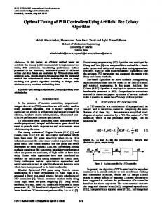
In order to investigate practical implementation of the proposed tuning method, two experiments were performed on a 1-DOF setup shown in Figure 10. The setup consists of a light weight link with an inertia of J = 0.002Kgm2 driven by an electromagnetic actuator. The first positioning experiment uses a stiffness parameter kc which was identified based on a defined performance requirement. On the second experiment, the effect of varying the stiffness value kc on system performance results was investigated.
80 70
Fig. 10.
60 50
20
40
60
80
100
A Fig. 8.
be achieved with the controller for different values of A. Choosing a phase lead of 65◦ , the design parameter is chosen as A = 15. Substituting known parameters in (18) and (22) yields a maximum phase lead frequency wm = 93.3rad/sec. Then (17) and (16) give a stiffness of kc = 2400N/m, damping constant b = 120N s/m, virtual mass mc = 0.1 and interconnection spring stiffness k = 36000N/m. Simulation results shown in Figure 9 indicate satisfactory behavior by the system with the error staying below the allowable maximum value.
Design parameter A vs. maximum phase lead for ζ = 1
For a damping ratio ζ = 1, Figure 8 plots equation (19) and shows the maximum phase lead φmax that can
A 1 D.O.F experimental setup used
The experiment used a setpoint position which has a maximum speed of x˙ vmax = 2rad/s to move the link with critically damped behavior and a maximum allowed error of emax = 0.1rad. As a result, the controller parameters were set as ζ = 1, A = 15, kc = 3.36N m/rad and b = 0.168N ms/rad. The experimental results indicate a behavior which yielded a maximum error of emax = 0.106rad that is very close to our desired performance requirement. See Figure 11. Unlike simulation results which didn’t consider actuator dynamics and friction in the model, the experimental result also indicated a steady state error of ess = 0.009rad.
4961
Fig. 11.
Experimental result - Positioning a 1 D.O.F link
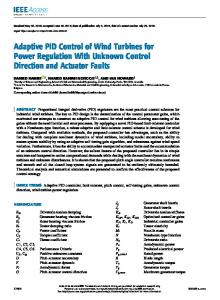
On the second experiment, results from the first experiment were compared with a more compliant system of kc = 1N m/rad and a less compliant system of kc = 5N m/rad. As seen from the results in Figure 12, increasing the compliance of the system by lowering kc affects the performance of the system by increasing the tracking as well as setpoint error.
Fig. 12.
Experimental result - Motion Error for different values of kc
VI. C ONCLUSION In this paper a performance based tuning of a damping injection framework impedance controller was presented. The controller allows shaping of the system compliance by adjusting kc and due to its passive nature, it is a preferred method of control for robots that operate in an unstructured human environment. The position based performance requirement added onto the framework can be used to designate a bounded safety region which could be reached by the robot during motion. In addition to the purely position based performance criteria used in this paper, safety criteria should also be considered to select the compliance of the system if this controller design approach is to be used for a human-friendly robot. The presence of friction and uncertainty of the plant’s mass parameter result in a slightly higher than expected setpoint as well as tracking errors in the damping injection controller. In order to compensate these low frequency errors, an integrator could be added to the controller. But the addition of this physically uninterpretable integrator element nullifies the passivity nature of the system and compromises the compliance felt by a user during interaction. In order to enhance performance while preserving passivity of the
control system, passive compensation of frictional forces should be investigated. The damping injection impedance controller can easily be extended to a multidimensional case to control multilink robotic manipulators and it has been applied for multilimb grasping application [15]. In the multidimensional implementation the desired compliance is given in cartesian space while the damping injection and actuation are done in joint space. However, adding a performance based impedance controller tuning method for multi-link robots remains an open problem with challenges such as converting desired cartesian stiffness to corresponding joint stiffness equivalent, dealing with strong non-linearity, more parameter uncertainty and inherent joint flexibility. R EFERENCES [1] J. E. Colgate and N. Hogan, “Robust control of dynamically interacting systems,” International Journal of Control, vol. 48, no. 1, pp. 65–88, 1988. [2] N. Hogan, “Impedance control - An approach to manipulation. I Theory. II - Implementation. III - Applications,” ASME Transactions Journal of Dynamic Systems and Measurement Control B, vol. 107, pp. 1–24, Mar. 1985. [3] S. Stramigioli, “Creating artificial damping by means of damping injection,” in In Proceedings of the ASME Dynamic Systems and Control Division, 1996, pp. 601–606. ˚ om and T. H¨agglund, “The future of pid control,” Control [4] K. J. Astr¨ Engineering Practice, vol. 9, no. 11, pp. 1163–1175, 2001. [5] A. O’Dwyer, Handbook Of PI And PID Controller Tuning Rules. Imperial College Press, 2009. [6] A. Bicchi and G. Tonietti, “Fast and ”soft-arm” tactics [robot arm design],” Robotics Automation Magazine, IEEE, vol. 11, no. 2, pp. 22 – 33, june 2004. [7] H. Kazerooni, T. Sheridan, and P. Houpt, “Robust compliant motion for manipulators, part i: The fundamental concepts of compliant motion,” Robotics and Automation, IEEE Journal of, vol. 2, no. 2, pp. 83 – 92, jun 1986. [8] C. Secchi, S. Stramigioli, and C. Fantuzzi, Control of Interactive Robotic Interfaces: A Port-Hamiltonian Approach, ser. Springer Tracts in Advanced Robotics. Springer, 2007. [9] K. Kanjanawanishkul and A. Zell, “Path following for an omnidirectional mobile robot based on model predictive control,” in Robotics and Automation, 2009. ICRA ’09. IEEE International Conference on, may 2009, pp. 3341 –3346. [10] G. Ferretti, G. Magnani, and P. Rocco, “Impedance control for elastic joints industrial manipulators,” Robotics and Automation, IEEE Transactions on, vol. 20, no. 3, pp. 488 – 498, june 2004. [11] J. van Dijk and R. Aarts, “Analytical one parameter method for pid motion controller settings,” in In Proceedings of IFAC Conference on Advances in PID Control, Mar 2012. [12] W. Wakeland, “Bode compensator design,” Automatic Control, IEEE Transactions on, vol. 21, no. 5, pp. 771 – 773, oct 1976. [13] D. de Roover, “Motion control of a wafer stage. a design approach for speeding up IC production,” Ph.D. dissertation, Delft University of Technology, 1997. [14] B. Babakhani and T. J. A. de Vries, “On the stability properties of P(I)D-controlled motion systems,” in 5th IFAC Symposium on Mechatronic Systems, Cambridge, Massachusetts, USA. IFAC, 2010, pp. 473–477. [15] C. Melchiorri, S. Stramigoli, and S. Andreotti, “Using damping injection and passivity in robotic manipulation,” in Proceedings of IEEE/ASME International Conference on Advanced Intelligent Mechatronics, 1999, pp. 979 –984.
4962