Aug 11, 2004 - ... by sleep transistor insertion are tightly controlled thanks to: (i) a post-layout ... Keywords. Leakage Power, Sleep Transistor, Sub-Threshold Current. 1. .... lay: It selects for power gating the subsets of cells that give maximum ...
5.1
Post-Layout Leakage Power Minimization Based on Distributed Sleep Transistor Insertion Pietro Babighian Luca Benini Alberto Macii Enrico Macii Politecnico di Torino Universita´ di Bologna Politecnico di Torino Politecnico di Torino Torino, ITALY Bologna, ITALY Torino, ITALY Torino, ITALY
ABSTRACT
currents are still dominant with respect to gate currents (although the trend shows that the latter grows more rapidly as technology scales). Thus, this paper addresses specifically the sub-threshold component of the overall leakage current. A number of leakage reduction techniques move from the observation that sub-threshold current in a stack of OFF transistors is greatly reduced with respect to the single transistor case. This is due to the exponential decrease of subthreshold currents with decreasing gate-source voltage Vgs . While Vgs = 0 for a single OFF transistor, it becomes negative for the top transistors in a stack. As a consequence, leakage current is effectively cut off for the entire stack. Quantitative analyses reported in the literature [3] show that leakage current can be decreased by one order of magnitude by simply stacking two transistors. Clearly, the main problem with transistor stacking is that the effective resistance of a series connection of transistors is higher than that of a single transistor, and therefore adding transistors in the pull-down and/or pull-up of logic CMOS gates significantly decreases their switching speed. To reduce the performance impact associated to transistor stacking, a common technique is to connect a number of CMOS gates to a virtual ground node, which is then connected to the ground node through a large sleep transistor, whose gate is driven by a sleep-control signal. When the transistor is OFF, leakage is reduced for all gates connected to the virtual ground. At the same time, when the transistor is ON, its large size guarantees a highly conductive path for the discharge currents coming from the gates. Even more importantly, the capacitance of the virtual ground greatly helps the dynamic performance of the gates, by providing a lowimpedance AC path to ground. Even in presence of these clear advantages, the shared sleep transistor approach faces several challenges. First, sleep transistors have a significant cost in terms of area. Second, and most important, they slow-down standard CMOS gates. We distinguish two main speed effects, namely slowdown of power-gated logic cells when the circuit is active (active slow-down), because of the increased pull-up/pulldown resistance and the re-activation delay for re-enabling a set of powered down cells. While huge sleep transistors controlling a large number of cells are desirable for minimizing active slow-down (thanks to the virtual ground effect), they are obviously very expensive in terms of area and reactivation delay. Distributed sleep transistor approaches [7, 8] represent a compromise solution. Smaller clusters of cells can be gated with smaller sleep transistors, which can be more easily embedded in unused spaces of existing layouts.
This paper introduces a new approach to sub-threshold leakage power reduction in CMOS circuits. Our technique is based on automatic insertion of sleep transistors for cutting sub-threshold current when CMOS gates are in stand-by mode. Area and speed overhead caused by sleep transistor insertion are tightly controlled thanks to: (i) a post-layout incremental modification step that inserts sleep transistors in an existing row-based layout; (ii) an innovative algorithm that selects the subset of cells that can be gated for maximal leakage power reduction, while meeting user-provided constraints on area and delay increase. The presented technique is highly effective and fully compatible with industrial back-end flows, as demonstrated by post-layout analysis on several benchmarks placed and routed with state-of-the art commercial tools for physical design.
Categories and Subject Descriptors B.7.2 [Integrated Circuits]: Design Aids—layout, placement and routing
General Terms Algorithms, Experimentation
Keywords Leakage Power, Sleep Transistor, Sub-Threshold Current
1.
INTRODUCTION
Leakage power consumption is a growing concern in integrated circuit design. Nanometer CMOS transistors are characterized by significant sub-threshold and gate leakage currents [1] and feature size scaling is exacerbating this problem. In absence of revolutionary technology advances (e.g., high-k dielectrics, new transistor structures), design techniques to reduce leakage power are now critical. As a result, leakage reduction has recently become a cross-cutting issue at all levels of abstraction [2], from device to architecture. In today’s technologies (i.e., 90nm), sub-threshold leakage
Permission to make digital or hard copies of all or part of this work for personal or classroom use is granted without fee provided that copies are not made or distributed for profit or commercial advantage and that copies bear this notice and the full citation on the first page. To copy otherwise, to republish, to post on servers or to redistribute to lists, requires prior specific permission and/or a fee. ISLPED’04, August 9–11, 2004, Newport Beach, California, USA. Copyright 2004 ACM 1-58113-929-2/04/0008 ...$5.00.
138
Furthermore, it is easier to individually select the size of the sleep transistors to provide localized and fine-tunable control on re-activation delay. In this paper, we contribute a complete methodology for layout-aware, distributed sleep transistor insertion for cell clusters that have physical proximity. Our insertion style is fully compatible with industry-standard row-based layout styles and the supporting design tools. Sleep transistor cells are chosen from a library of cells that has been designed for high layout efficiency. These cells are inserted at the boundaries of existing cell rows, causing minimal disruption in placement and routing. Selection of the most appropriate sleep transistor cell size to control each group of cells is driven by the models of [10]. Furthermore, we present a novel gate clustering algorithm that groups together sets of cells to be controlled by the same sleep transistor; the cost function used by the algorithm to select the cells that have to be gated is layout-aware, i.e., it takes advantage of cell placement information. The algorithm accounts for constraints on area overhead, active slow-down and re-activation delay: It selects for power gating the subsets of cells that give maximum power reduction, without exceeding user-specified bounds for delay and area costs. The effectiveness of the proposed methodology has been benchmarked on a set of design examples for which a physical implementation has been obtained through commercial EDA tools; the results we have achieved show a reduction of leakage power ranging from 74% to 83%, depending on the circuit. It is important to stress the point that, thanks to the strategy used for gate clustering, the optimized designs have a tightly controlled delay and area penalty. Therefore, the user is allowed to explore the trade-off between leakage reduction and delay or area overhead. The remainder of the paper is organized as follows. In Section 2 we briefly review previous work on leakage reduction techniques. Section 3 highlights the sleep transistor insertion methodology. Section 4 describes the layout-aware cell selection algorithm. Section 5 provides experimental results obtained on a set of benchmark circuits, while Section 6 closes the paper.
2.
(MTCMOS) technologies [7, 8]. They reduce stand-by power consumption by inserting a high-VT H cut-off MOSFET (i.e., a sleep transistor) in series to the initial low-VT H circuit. Hence, sub-threshold leakage current is reduced by the sleep transistor while performance loss is controlled. The latter happens thanks to two factors: First, the sleep transistor can be made very large (i.e., with low resistance), because it is shared among many cells; second, the large capacitance of the net connecting the cells and the sleep transistors provides a low-impedance AC discharge path, i.e., a virtual ground for the transient currents created by the switching gates. MTCMOS techniques present two drawbacks. First, they still require process modifications for supporting the highVT H of the sleep MOSFET. Second, when a circuit is deactivated by power gating, it takes a non-negligible amount of time to wake up and re-activate it, simply because the large sleep transistor must be switched on and it must initially discharge the slow virtual ground capacitance. The first drawback is eliminated if the sleep transistor is fabricated with the same threshold as the other transistors in the circuit. Even though leakage reduction is less substantial, the stacking effect still provides significant benefits. To address the second limitation, several distributed sleep transistor approaches have been proposed, where multiple smaller sleep transistors are instantiated. The main advantage of distributed sleep transistor implementations is a faster re-activation time when exiting the sleep state. Unfortunately, most techniques presented in the past work at the logic and circuit level, and thus they do not fully take into account the information about the placement of the logic cells. This is a serious inconvenient, because connecting cells that are placed far apart to the same virtual ground and sleep transistor can cause severe wiring congestion. The only two approaches available in the literature that account for cell placement are [7, 8]. However, they both assume a full-custom design style, where single transistors can be arbitrarily placed inside the chip. In the sequel, we describe a distributed sleep transistor implementation style which is fully compatible with standard-cell physical design tools that support row-based layouts, where logic gates are placed in rows of adjacent cells with connection channels between rows.
PREVIOUS WORK
Several approaches for succesfully minimizing sub-threshold leakage power dissipation in stand-by mode have been presented in the literature. In [4], a Variable-VT H (VTCMOS) strategy is adopted in order to cut off leakage current. In particular, it applies back-gate bias by exploiting body effect. This requires modification to cell libraries and, above all, specific technology support [5]. Other approaches are Dual-VT H strategies, which perform leakage power reduction by partitioning a circuit into critical and non-critical path regions. Subsequently, low-VT H and high-VT H transistors are used for implementing gates in the critical and non-critical regions, respectively [6]. The shortcoming of this approach is that many circuits may have a significant number of critical paths. As a consequence, high-VT H transistors may be used for an excessively small percentage of gates to result in a significant leakage power reduction. Furthermore, supporting multiple thresholds implies complexity increase in the fabrication process, as well as potential difficulties from the tool support perspective. A popular approach for stand-by power reduction is represented by the adoption of emerging Multi Threshold CMOS
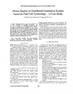
3. AUTOMATIC STI METHODOLOGY Most approaches for distributed sleep transistor insertion (STI), including those that account for physical information (i.e., cell placement) [7, 8], are characterized by a significant cost, both in area and delay, that is associated to the instantiation of the sleep transistor cells. In this section, we describe an automatic methodology for distributed STI that allows the designer to keep under control the area and the delay overhead, thanks to an accurate analysis of the circuit layout to be optimized. The entry point of the flow is a circuit for which placement is already done using a row-based style. We assume that all the cells in the circuit can be potentially controlled by sleep transistors that cut off the sub-threshold leakage currents when the cells are in stand-by mode. The control signal that drives sleep transistors is thus assumed to be available from some external module (e.g., a microprocessor). Sleep transistors are inserted on a row-by-row basis, at the boundaries of each row, as shown in Figure 1, and they are
139
connected to a common virtual ground. The sleep transistors are picked from a library that contains devices of different sizes, driving strengths and speed, fully compliant with the cells belonging to the technology library; the sleep transistor cells in the library have been designed and fully characterized using the procedure of [10].
���
0000000000000000000000000000000000000 1111111111111111111111111111111111111 000 111 000000 111111 VDD VDD000000 VDD 0000000000000000000000000000000000000 1111111111111111111111111111111111111 000 111 111111 0000000000000000000000000000000000000 1111111111111111111111111111111111111 000 111 000000 111111
S
��� Vgd
GND
S 0000 1111 00000000000000000000000000000000000000 11111111111111111111111111111111111111 1111 0000 11111111111111111111111111111111111111 00000000000000000000000000000000000000 000000 111111 1111 0000
000000 111111 0000 1111 VDD000000 00000000000000000000000000000000000000 VDD 11111111111111111111111111111111111111 111111
���
S
Figure 2: Controlling Area Overhead During STI.
Vgd
GND
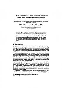
S cording to the congestion tolerance) and used for accommodating the sleep transistors. Confining the implementation of the sleep transistors into the space that becomes available after compaction would have the desirable effect of zeroing the area overhead, that is, the layout after STI would have the same size as the original one. However, this solution may be overly conservative, as it may prevent the possibility of power-gating the majority of the cells in the row. In fact, the larger the number of cells in a row that are controlled by the sleep transistor, the larger the size of the transistor to be inserted (to preserve the active slow-down factor). In addition to that, not all the available space reclaimed through compaction can be used by the sleep transistor cells; some spacing has to be maintained between sleep transistors and standard cells in order to avoid undesirable electrical phenomena. Since in a row-based design cells are placed by abutment, if such a space is not maintained, an electrical contact between the ground of a sleep transistor and the virtual ground of the adjacent cell (if gated) is generated with the undesirable pitfall of shorting the sleep transistor ground and thus nullifying its stacking effect. In order to increase the potential of STI (i.e., the possibility of power-gating many cells in a row), we can trade transistor size for area overhead. Rows can be widened by a certain (tightly controlled) amount in order to allow the insertion of larger transistors, thus enabling the gating of more cells in the row (see Figure 2-c).
111111 000000 000 111 0000000000000000000000000000000000000 1111111111111111111111111111111111111 000 111111 111 0000000000000000000000000000000000000 1111111111111111111111111111111111111 VDD000000 000000 000 0000000000000000000000000000000000000 VDD 111111 111 1111111111111111111111111111111111111
Figure 1: Sleep Transistors Insertion in a RowBased Layout. The number and the position of the cells driven by each sleep transistor is selected through the algorithm described in Section 4, which accounts for the area and delay overhead that are allowed through a user specification. In the remainder of this section, we briefly highlight the principles that allow our algorithm, described in Section 4, to tightly control the area and delay penalties that are caused by distributed STI.
3.1 Controlling Area Penalty In a row-based layout style, the floorplan of a circuit is partitioned into rows separated by routing regions, known as channels. If a few metal layers are supposed to be used for routing, the interconnect scheme of the design can be completed thanks to the routing resources provided by such regions. This may be true even if an aggressive over-the-cell routing style (four metal layers or more) is adopted, since interconnects might be so complex to require more horizontal routing resources. In order to satisfy performance constraints and facilitate routability, it is common practice placing cells after channel heights are fixed and the number and positions of cell sites for each row is determined. Clearly, this leads to the presence of empty spaces (white spaces) which are allocated between cells mainly for alleviating local wiring congestion (see Figure 2-a). We propose to take advantage of part of the area of such empty regions for sleep transistor insertion in accordance to the wiring congestion tolerance. The presence of interrow spacings eases the use of such a strategy. In fact, since the heights of the channels are fixed before placement, they might not be fully exploited by the router, which would instead utilize the channels to the maximum extent, leaving several white spaces in the layout rows. The amount of available space for each layout row is determined (see Figure 2-b) by performing row compaction (ac-
3.2 Controlling Delay Penalty In order to minimize the leakage power consumption, assuming that enough area slack is available, all cells in the circuit should be power-gated. Unfortunately, this solution would imply a delay increase that would go far beyond the intrinsic performance penalty caused by STI (i.e., active slow-down, which is related to the size of the sleep transistors). In fact, the re-activation time needed by the sleep transistors, when they change from the off-state to the on-state, may be longer than the response time of many cells in the design (especially those placed closed to the circuit primary inputs). This is mainly true if the activation of all the gates within the circuit is influenced by the inserted sleep transistors. In other words, when the circuit changes from the stand-by mode to
140
the active mode, a penalty in delay corresponding to the sleep transistors re-activation times must be payed. Such a penalty can be traded for a smaller reduction of the subthreshold leakage current in stand-by mode by limiting the number of cells that will be power-gated. In particular, it is possible to trade (or even nullify) the re-activation delay penalty by preventing the power gating in the circuit of some (all) of the cells whose arrival times are shorter than the re-activation delay of the sleep transistors. Figure 3 shows an example of how cells to which power gating is not applied are selected based on timing information; shaded gates have arrival times that are shorter than the re-activation delay required by the sleep transistor that is supposed to control them. Avoiding power-gating of all the shaded cells will ensure a zero re-activation delay overhead.
1: 2: 3:
4: 5: 6: 7:
8: 9: 10: 11: 12: 13: 14: 15: 16: 17: 18: 19:
Figure 3: Example of Selective Power Gating. The fact that, for a given constraint on the re-activation delay, not all the cells in a row are power-gated may provide a further benefit of the application of the proposed methodology; in particular, the size of the sleep transistor in that row may end up being smaller than that of the transistor that would be able to control all the gates in the row. This would have the twofold advantage of reducing the active slow-down delay overhead observed in normal active operation (although it will never become zero), and of increasing the opportunities for further row compaction.
4.
GateCluster (Techlib, Sleeplib, Sim_Curr, DEF_File, A_OH, RT_OH) { /* List of clusters - one per row */ Cluster_List = {}; /* Timing analysis by topological exploration of gate netlist */ Timing_List = get_timing_path (All_Gate_Outputs); Sorted_List = decreasing_sort (Timing_List); /* Loop over all layout rows */ for (i=1 to Tot_Row_Number) { Stop = 0; /* Row compaction (if possible), determine avalable space */ Av_Space = compact_row(DEF_File, Row(i)); /* Augment space by allowed area overhead */ TWidth = A_OH + Av_Space; /* Pick sleep transistor from library */ Sleep = pick_sleep_transistor (Sleeplib, TWidth); /* Calculate max sustainable current */ Iav = extract_max_current (Sleep) /* Cluster for row i initialized to empty set */ Cluster = {}; /* Timing exploration of the row */ while (Stop == 0) { /* Choose gates closest to primary outputs */ Gate_List = choose_all_gates (max_timing(Timing_List)); /* If many cells in Gate_List, select most dissipating one */ if {more than one element in Gate_List} { Cell = extract_maxlk_gate (Gate_List, Techlib); } else { Cell = Gate_List; } /* Calculate cell re-activation time */ RT = evaluate_react(Cell); /* Update maximum current available at sleep transistor */ Iav = Iav - max_gate_current (Cell Sim_Curr); /* Check whether cell can be power-gated */ if { RT = 0} { /* Add cell to cluster */ Cluster = add_cell_to_cluster (Cell); } else { Stop = 1; } } Cluster_List = add_cluster_to_list (Cluster); } }
Figure 4: Gate Clustering Algorithm. The maximum sustainable current by the chosen transistor is calculated in Line 7; the cell selection process performs a gate-by-gate exploration of each row (while loop of Line 8), starting from the cell with the longest timing path and going back towards the primary inputs (line 9). If more than one cell is available, the algorithm selects the one with maximum leakage current (Lines 10-14). For each selected gate, the impact of the gate itself on the sleep device re-activation time is evaluated (Line 15) and the remaining current at the sleep transistor is computed (Line 16). If the required re-activation time has not been violated and the sleep transistor is able to sustain the current associated to the selected gate (Line 17), such a gate is added to the current cluster (Line 18) and the exploration goes on. Otherwise (Line 19) the cluster is complete for the i-th row and therefore it is added to the overall list of clusters (Line 20) before the procedure continues with the next row.
GATE CLUSTERING
Objective of the clustering procedure is that of identifying groups of cells that will be power-gated by the same sleep transistor cell. In particular, the clustering algorithm we have implemented takes into account both the physical positions of the cells in the layout and their timing paths.The pseudo-code of the proposed algorithm is shown in Figure 4. On the basis of the previous considerations, gates closer to primary outputs (hence with longer timing paths) are good candidates to be clustered since the sleep transistor gating them will be already turned on when their inputs will become stable. Initially, timing information about each gate of the layout is captured and listed in decreasing timing order (Lines 12). Then, the algorithm proceeds one layout row at a time (for loop of Line 3). The available space for row i after compaction is computed (Line 4); further space is also added according to the area overhead allowed by the user (Line 5) and the sleep transistor of the appropriate size is retrieved from the library (Line 6).
5. EXPERIMENTAL RESULTS The viability and effectiveness of the proposed sleep transistor insertion methodology has been assessed on a set of logic blocks that are part of an industrial design provided by STMicroelectronics. The standard cell library we used for our experiments is the 130nm HCMOS9 provided by STMicroelectronics. The sleep transistor cells have been designed with the Ca-
141
Benchmark Block1 Block2 Block3 Block4 Block5 Block6 Avg.
PL [mW] 0.11 0.19 0.16 0.26 0.12 0.46
Orig Pdyn+int [mW] 0.29 0.22 0.31 0.60 0.29 0.88
Ptot [mW] 0.40 0.41 0.47 0.86 0.41 1.34
PL [mW] 0.02 0.04 0.04 0.05 0.03 0.09
Opt Pdyn+int [mW] 0.32 0.24 0.33 0.63 0.32 0.98
Ptot [mW] 0.34 0.28 0.37 0.68 0.35 1.07
PL [%] 78.9 80.0 74.6 82.7 78.9 83.5 79.7
∆ Pdyn+int [%] -9.0 -10.1 -8.8 -5.0 -9.7 -12.4 -9.6
Ptot [%] 15.0 31.0 21.2 18.6 12.5 20.1 18.9
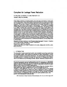
Table 1: Results: Power Consumption. area of the original (column Area Orig) and of the minimum leakage (column Area Opt) circuits and the percentage of area overhead due to the sleep transistors insertion. We observe that, in spite of the fact that the area overhead constraint has been set to 5%, only an average area increase of 2.5% did actually occur. This is due to the fact that, as not all the cells in each row can be power-gated due to the constraint posed on re-activation delay (i.e., zero overhead), some of the sleep transistors have been down-sized, as the currents they need to sustain are lower than what was initially planned; thus, a further step of layout compaction has allowed us to recover some additional area. For the sake of completeness, we conclude this section by reporting, for one of the benchmarks (i.e., Block6), partial snapshots (i.e., the upper-left corner – displaying of the full layouts is avoided for the sake of readability of the images) of the layouts for the original circuit (Figure 5) and for the minimum leakage implementation (Figure 6).
dence Virtuoso tool, following the rules of the standard cells in the library. Each cell contained a sleep transistor and the appropriate buffering circuitry, and the library consisted of a total of 20 different cells. The size of the sleep transistor cells has been determined so as to guarantee a total performance degradation due to active slow-down below 5% [10] w.r.t. the circuits that do not include sleep transistor cells. The gate clustering algorithm was run by posing a zerooverhead constraint on the re-activation delay, thus ensuring that the overall performance degradation was never higher than the intrinsic 5% originated in active-mode operation by the insertion of the sleep transistor. On the other hand, a constraint on the allowed area overhead of 5% w.r.t. the original circuits was tolerated. This value was determined after analyzing the sensitivity of leakage power on area overhead of some of the benchmark circuits we have considered. The results of our analysis indicated that widening the layout rows by more than 5% did not really provide further leakage power savings, as growing the size of the transistors did not lead to the consideration of more cells for powergating. This was clearly a consequence of the zero-overhead constraint posed on the re-activation delay; no other cells could be power-gated without introducing a timing violation, even if a larger transistor would have been inserted. Post-layout simulation was performed to obtain leakage power consumption and timing information for each circuit. The power results, expressed in mW , for all the experiments are collected in Table 1. In particular, columns Orig and Opt report, for the original and for the minimum leakage circuits, the leakage power (PL ), the dynamic and internal power (Pdyn+int ), the total power (Ptot ) and the corresponding savings and penalties. Leakage power savings are, on average, around 80%. The average penalty in dynamic and internal power introduced by the sleep transistors and the extra routing is around 10%. This leads to an overall power savings, averaged over all the benchmarks, of 19%. Benchmark
Gates
Sleep
Block1 Block2 Block3 Block4 Block5 Block6
1852 1916 2215 2267 2302 2612
14 14 22 13 26 20
Area Orig [µm2 ] 64912 65210 65053 65412 65918 70298
Area Opt [µm2 ] 66794 66710 66550 66524 68159 71703
Figure 5: Layout of the Original Circuit. On the left hand-side of Figure 6 the inserted sleep transistor cells are clearly visible. Next to the sleep transistor cells it is also visible the “column” of empty slots that are left between the sleep transistors and the standard cells for isolation purposes.
∆ [%] 2.9 2.3 2.3 1.7 3.4 2.0
6. CONCLUSION Leakage power consumption is becoming dominant in deep sub-micron CMOS technologies, and different approaches for limiting it are now appearing in the scientific literature. In this paper, we have presented a novel methodology for sub-threshold leakage power reduction based on the idea of inserting distributed sleep transistors into standard-cell circuits with the purpose of cutting off the leakage current
Table 2: Area Results. Area results are summarized in Table 2, which reports the number of gates of the original circuits (column Gates), the number of inserted sleep transistor cells (column Sleep), the
142
[2] T. Sakurai, “Low-Power and High-Speed VLSI Design with Low Supply Voltage through Cooperation between Levels,” ISQED-02: IEEE International Symposium on Quality of Electronic Design, pp. 445-450, San Jose, CA, March 2002. [3] D. Lee, W. Kwong, D. Blaauw, D. Sylvester, “Simultaneous Subthreshold and Gate-Oxide Tunneling Leakage Current Analysis in Nanometer CMOS Design,” ISQED-03: IEEE International Symposium on Quality of Electronic Design, pp. 287-292, San Jose, CA, March 2003. [4] T. Kuroda, T. Fujita, S. Mita, T. Nagamatsu, S. Yoshioka, K. Suzuki, F. Sano, M. Norishima, M. Murota, M. Kako, M. Kinugawa, M. Kakumu, T. Sakuray, “A 0.9-V, 150-MHz 10-mW 4mm2 2-D Discrete Cosine Transform Core Processor with Variable Threshold-Voltage (VT) Scheme,” IEEE Journal of Solid-State Circuits, Vol. 31, No. 11, pp. 1770-1779, November 1996. [5] H. Kawaguchi, K. Nose, T. Sakurai, “A Super Cut-Off CMOS (SCCMOS) Scheme for 0.5-V Supply Voltage with Picoampere Stand-By Current,” IEEE Journal of Solid-State Circuits, Vol. 35, No. 10, pp.1498-1501, October 2000. [6] L. Wei, Z. Chen, K. Roy, M. Johnson, Y. Ye, V. De, “Design and Optimization of Dual-Threshold Circuits for Low-Voltage, Low-Power Applications,” IEEE Transactions on VLSI Systems, Vol. 7, No. 1, pp. 16-24, March 1999. [7] M. Anis, S. Areibi, M. Elmasry, “Dynamic and Leakage Power Reduction in MTCMOS Circuits using an Automated Efficient Gate Clustering Technique,” DAC-39: ACM/IEEE Design Automation Conference, pp. 480-485, New Orleans, LA, June 2002. [8] C. Long, L.He, “Distributed Sleep Transistor Network for Power Reduction,” DAC-40: ACM/IEEE Design Automation Conference, pp. 181-186, Anaheim, CA, June 2003. [9] Cadence Design Systems, BuildGates Extreme, www.cadence.com [10] P. Babighian, L. Benini, E. Macii, “Sizing and Characterization of Leakage-Control Cells for Layout-Aware Distributed Power Gating,” DATE-04: IEEE Design Automation and Test in Europe, pp. 720-721, Paris, France, February 2004.
Figure 6: Layout of the Minimum Leakage Circuit. when the gates in the circuit are not active. The distinguishing features of the proposed solution are: (1) STI is driven by a layout-aware cost function. (2) STI is done with tunable performance and area penalty. We have presented an algorithm for gate clustering that allows selective power-gating of circuit cells and we have validated it on a set of benchmark circuits using an industrystrength design flow. Experimental data show leakage power reductions around 80% (total power savings, accounting for cell dynamic and internal power, are around 19%), with a circuit delay increase of 5% caused by active-mode slow-down due to the insertion of the sleep transistors and an average area overhead around 2.5%.
7.
ACKNOWLEDGMENT
This work is supported, in part, by STMicroelectronics and by Intel Corp. The authors would like to thank Antonio Remollino for his valuable help in sleep transistor cell design.
8.
REFERENCES
[1] J. Kao, S. Narendra, A. Chandrakasan, “MTCMOS Hierarchical Sizing based on Mutual Exclusive Discharge Patterns,” DAC-35: ACM/IEEE Design Automation Conference, pp. 495-500, San Francisco, CA, June 1998.
143