Practical Region-based Matching for Stereo Vision Brian McKinnon1 and Jacky Baltes1 Department of Computer Science University of Manitoba Winnipeg, MB Canada R3T 2N2
[email protected] http://avocet.cs.umanitoba.ca
Abstract. Using stereo vision in the field of mapping and localization is an intuitive idea, as demonstrated by the number of animals that have developed the ability. Though it seems logical to use vision, the problem is a very difficult one to solve. It requires the ability to identify objects in the field of view, and classify their relationship to the observer. A procedure for extracting and matching object data using a stereo vision system is introduced, and initial results are provided to demonstrate the potential of this system.
1
Introduction
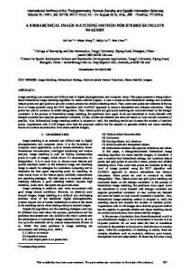
This paper describes our research into stereo vision for simultaneous localization and mapping (SLAM). In this paper we present a novel algorithm for matching stereo images based on regions extracted from a stereo pair. Another notable feature of our approach is that it is implemented using commodity hardware. The overall goal of the project is to develop urban search and rescue (USAR) robots that can generate maps of an unstructured environment given a sequence of stereo images and find victims within this environment. In our research, we focus on the use of vision as sole sensor. The use of vision as the sole sensor on a mobile robot is considered by some to be a radical idea. Today, most work in SLAM uses LADAR (laser scanners), which provide highly accurate point clouds in 3D space. The advantage of vision is that cheap commodity hardware can be used. Furthermore, developing methods for extracting and representing the necessary information (e.g., ground plane, walls, doors, other objects) is a wide open problem. The USAR domain adds to this complexity because the real-time constraints imposed on the mobile robot. To test our approach, we take part in the NIST sponsored USAR competitions. The NIST domain (see Fig. 1) is a challenging domain for today’s robots (especially ones using vision) since it includes uneven lighting, glass, mirrors, and debris. In this paper, the first stage of the vision-based mapping and localization system is described. This involves image processing to extract and represent
Fig. 1. NIST Reference Test Arenas for Autonomous Mobile Robots at the AAAI 2000 in Austin, Texas, USA.
objects in the captured image. Included is a description of the methods currently being used by other researchers. Additionally, the problem of localization will be discussed and a variety of systems will be examined, including vision-based and more traditional distance sensor-based solutions.
2
Related Work
Both region extraction and localization are active areas of research. There are a wide variety of solutions currently being investigated, many of these yielding promising results. The two most important steps in region extraction are identification and representation of features in the image. Research is still active in this area, since current systems encounter environments that cause failure rates to become unmanageable. Examples of systems currently being studied include [6] [3] and [4]. 2.1
Scale Invariant Feature Extraction
In [6] an object recognition system is introduced that has become known as Scale Invariant Feature Extraction (SIFT). It uses a feature representation that is invariant to scaling, translation, rotation, and partially invariant to changes in illumination. The output of this system is a set containing the orientation, position, relative location, and colour gradient of key features within an image. Scale invariance is achieved through the use of the Gaussian kernel as described in [5]. For rotational invariance and efficiency, key locations are selected at the maxima and minima from the difference of the Gaussian function applied in scale space. A threshold is applied to the gradient magnitude for robustness. This is useful since illumination changes may greatly affect the gradient magnitude, however it should have little impact on the direction. Once a set of keys are defined for a given object, live images are scanned and objects are selected using
a best-bin-first search method. Bins containing at least three entries for an object are matched to known objects using a least square regression. Experimental results show that the system is effective at detecting known objects, even in the presence of occlusion, since only three keys are necessary for a match to occur. This can be seen in figure 2. Using this method, a localization system has been implemented in [8].
Fig. 2. Using SIFT the sample objects(above) are searched from in the image(left). The keys generated are used to match the samples to the image(right). Images are from [6].
2.2
Blobworld Representation
The Blobworld representation is introduced in [3] as a means of performing image retrieval. Pixels in an image are assigned to a vector containing their colour, texture, and position. Colours are smoothed to prevent incorrect segmentation due to textures, and are stored using the L*a*b* colour format. L*a*b* representation shown in figure 3 contains three colour channels, L for luminosity, a for the colour value between red and green, and b for the colour value between yellow and blue. Texture features that are used include contrast, anisotropy, and polarity. Contrast is the difference between light and dark area, anistropy indicates the direction of the texture, and polarity measures how uniformly the texture is oriented. Regions are grouped spatially if they belong to the same colour/texture cluster. A gradient is generated in the x and y direction, containing the histogram value of pixels in that region. For matching, the user starts by selecting blobs from the image that will be used for comparison against the database. Regions are matched to the database by the quadratic distance between their histograms’ x and y values. The Euclidean distance for the contrast
and anisotropy texture are also used in the comparison. The best image is selected based on the similarity values for the selected blobs as shown in figure 4. This method was used as a basis for an optimal region match in [2], however it is unclear how robustly the method handles translation of the blobs. This system is not directly usable for localization, since blobs must be selected manually.
Fig. 3. The L*a*b* colour wheel. Image http://www.colorspan.com/support/tutorials/cmpl/lab.asp.
2.3
is
from
Wavelet-based Region Fragmentation
A recent approach to region extraction is known as Wavelet-based Indexing of Images using Region Fragmentation (WINDSURF) [1]. In this approach the wavelet transform is employed to extract colour and texture information from an image. The wavelet transform is similar in principle to a fast Fourier transform where data is represented using a wave form. A clustering algorithm is used on the output coefficients from the wavelet transform, producing regions that contain similar colour and texture waves. By using only the coefficients, regions are clustered without considering spatial information. This means that images cannot be compared based on the location of the regions, however it allows matching that is invariant to position and orientation differences. One limitation in this system is that the region count must be defined, so clustering of dissimilar regions can occur in the presence of images that contain more features than expected. The results of the transformation are shown in figure 5 using different region counts. Image retrieval is achieved by comparing the size, centroid, and features of regions from the sample image to those in the database images. Experimental results show that the system is capable of retrieving images which are semantically correlated to the sample. In the case of figure 6 a match could consist of images containing similar sized and textured blue and gray regions.
Fig. 4. This sample output from [3] shows the blobs generated from the sample, and images containing similar blobs that were retrieved.
Fig. 5. This image shows the results of applying the wavelet transform to sample image, using region count of 2, 10 and 4 respectively. Images are from [1].
Fig. 6. This shows the results of a sample wavelet query using the dome of St. Peter’s in Rome. Images are from [1].
3
Implementation
In order to perform stereo matches we must first process the raw captured images. The process implemented in this paper consists of 5 steps: 1. 2. 3. 4. 5.
Colour Correction Image Blur Edge Detection Region Extraction Stereo Matching
Each processing stage has an important role in transforming the image. The result must be an accurate representation of the objects contained in the image. 3.1
Colour Correction
Normalization of the colour channels is necessary to correct imbalances in the colour response of the two cameras. This is useful in situations where images are too bright or dark, or if a colour channel is over saturated. This allows more accurate matches between two separate images. The method used in this system relies on the mean and standard deviation of the colour channels. Calculating the mean and standard deviation of an image usually requires at least two passes through the image. In the first pass, the mean is calculated and in the second the differences to the mean are summed up. Applying the colour correction would result in a third pass. It is impossible to perform this much pre-processing for each image and maintain a reasonable frame rate. To speed up the computation of colour normalization, we use a pipelined approach. The key idea here is that mean and standard deviation of the image sequence are relatively constant over time. Therefore, we use the mean and standard deviation of previous images. At time t, the mean of the image at time t − 2 and the standard deviation at time t − 1 is being used. This means that colour correction has a negligible impact on the runtime. The colour of each channel is bounded by using the mean as the centre value and setting the range to a distance of two standard deviations plus and minus from the mean. This range is then stretched to cover the entire possible range of the colour channel. Using a distance of two standard deviations allows outliers to be discarded, which gives a more accurate representation of the true colour range of the image. 3.2
Image Blur
The blur that is applied to the image is important since raw images are prone to noise. This noise can be generated by lighting problems, textured surfaces, or a low quality capture device. The goal is to smooth the image so small inconsistencies can be ignored by the edge detection. There are many methods of applying a blur to an image. The simplest method, which was implemented in
Fig. 7. The normalization process helps balance the colours in the image by stretching the colour range of pixels.
the original version of the application, transformed the centre pixel to contain the average colour of the surrounding neighbourhood. The primary advantage of this method was simplicity, but it also operated very quickly on an image. The Gaussian blur is an improved method that provides smoothness and circular symmetry [9]. One feature that a Gaussian blur provides over simple blurring is the ability to repeat small areas of blur to generate large areas. The values used in a Gaussian blur are generally based on the binomial coefficients, or Pascal’s triangle. To apply a blur of N = k, coefficients are selected such that i + j = k. For example, to apply a 3x4 filter, k = 5 is selected, and then the coefficients at a depth of 2 and 3 are used. Depth 2 corresponds to the set {1 2 1}, and 3 corresponds to {1 3 3 1}. One set is applied to the image horizontally, and the second is applied vertically to the result of the first. The result stored in each pixel is normalized, with a division by the sum of the two coefficients. 3.3
Edge Detection
Edge detection is an essential component in the object extraction process. It allows boundaries to form, which provides assistance in the region growing process. For this, a Sobel edge detection is implemented, since it is simple, robust, and versatile. It involves applying convolution masks across the entire image. The Sobel edge masks used in the horizontal and vertical direction respectively are:
Fig. 8. The product of applying a Gaussian blur on the raw image.
−1 −2 −1 −1 0 1 −2 0 2 and 0 0 0 1 2 1 −1 0 1
The results of each mask are normalized with a division by four. The value from these transformations are tested against a threshold, that once exceeded indicates the presence of an edge. The edge pixels are stored within an edge map used in the region extraction. 3.4
Region Extraction
The region growing method that has been explored uses a stack-based growth that identifies matching pixels based on the colour channels match with the previously accepted pixels. The image is scanned linearly for pixels that have not been detected as edges and have not been previously examined. When a pixel is found, it is set as the start point for the region growing, and is pushed on to the stack to become the examined pixel. The neighbouring pixels to the top, bottom, left, and right are considered for addition to the region provided they have not been identified as edge pixels. Colour match is calculated by using the sum of squared error across all the colour channels (RGB). If the resulting value falls below a defined threshold then the match is considered to be acceptable. Initially, the neighbouring pixels are added to the region based on an acceptable colour
Fig. 9. The result of applying a Sobel edge detection to the blurred image.
match with only the examined pixel. Once a threshold size has been reached, neighbours are added based on the colour match with the mean colour value of all pixels in that region. Each time a pixel is accepted, it is pushed onto the stack and the process is repeated. Termination occurs once no pixels are acceptable matches with the current region. If the region has reached a threshold size then it is added to the list of identified regions. Regions below the threshold size are rejected, and each pixel is marked as previously examined to prevent additional small regions from being generated at a starting pointing in this area. The threshold value for the colour match is very small, and as a result a single object in the image could be separated into several small regions. There is no restriction on a new regions ability to expand into another region, and this overlap is used as the basis for merging regions into objects. Neighbouring regions are combined if the overlap exceeds a threshold of either a percentage of the pixels in the region ( generally used to merge smaller regions ), or a threshold number of pixels ( used for matching larger regions ). This method of overlap merging the objects, allows either shadow or glare to be joined properly without setting the colour match threshold to an excessively high value. Once completed, the objects are defined by: 1. 2. 3. 4. 5.
Size ( in pixels ), Mean colour value, Centroid x and y, Bounding box,and Region pixel map (i.e., mapping from pixels to associated regions)
These objects are then used as the feature points in the stereo matching process.
Fig. 10. Shown here is the resulting set of regions. Red dots indicate the centroid, and the colour represents the average colour of the region.
3.5
Stereo Matching
Once an image has been segmented, the shape of the object is used to identify matches between the stereo images. Objects from the two images are superimposed onto each other at the centroid, and the size of the union between the two is calculated. The union size is calculated by identifying pixels that are contained in both images. If a minimum percentage of pixels overlap, then the two objects are identified as a stereo pair. Though it is possible for an object to produce more than a single stereo pair, only the strongest match is considered. The displacement between the objects is calculated, and will later be used to determine the distance to the object. Before a match of stereo regions is considered, it must appear over a series of images. This is useful when attempting to ignore noisy and incorrect matches. Currently, the matching is done uncalibrated, so no consideration is given to the intrinsic or extrinsic properties of the camera. Therefore, matches can occur even in the presence of unreasonable displacement in the vertical direction. This does increase the number of incorrect matches, however, a substantial number of the matches are still correct. Since there are still many correct matches, it
may be possible to calibrate stereo cameras with no human interaction even in the presence of a significant alignment difference between the two cameras. Once calibrated the accuracy of the matching should increase dramatically.
Fig. 11. Matching regions are bounded by a coloured box, with a line going from the centroid to the centre of the image. Pink crosses indicate the presence of a strong match.
4
Experiments
This system has been implemented and tested using an unmodified area in the Computer Science department at the University of Manitoba. The robot used in this project, named Spike, is a one-sixth scale model of a Pt Cruiser with rear wheel drive. The radio controller has been modified to allow the vehicle to be controlled through the parallel port on any standard PC. The micro-controller is a C3 Eden VIA Mini-ITX running at 533MHz, with a 256Mb flash card. We developed our own mini version of the Debian Linux distribution refined for use on systems with reduced hard drive space. The vision hardware consists of two USB cameras capable of capturing 320 by 240 pixel images. The cameras are mounted on a servo that allows the stereo rig to pan in a range of plus or minus forty-five degrees. In figure 13 we demonstrate the matching ability of this system. The raw image has been segmented into 21 objects for the right image, and 25 objects for the left image. In this sample, seven stereo pairs have been generated, as indicated
Fig. 12. Spike, the mobile robot used for this experiment.
by the coloured boxs surrounding the matched pairs. Over the compete runtime in this sample, nine pairs were selected as strong stereo pairs, as indicated by the pink crosses on the resulting image. Five of these are both correct, and the regions appropriately represent the object in the image. Two of the matches are spatially correct, however these two should be represented as one. The system still has some difficulty when bright glares are reflected from smooth surfaces. The remaining two objects have been matched incorrectly.
Fig. 13. Demonstration of matching in an unknown environment.
Currently, the complete system runs at 0.5 frames per second. We are currently investigating methods for speeding up this process. In particular, the matching of regions is computationally expensive because the stereo system is uncalibrated at the moment. Therefore, regions must be compared against all other regions. By adding at least a rough calibration, most of these comparisons can be avoided, since for example, matching regions must have similar Y coordinates.
5
Conclusion
This paper presented the initial steps taken in the development of a vision-based autonomous robot. With the region-based object extraction and stereo matching implemented the ground work is laid for the development of the remaining components. These include 3D scene interpretation, mapping, localization, and autonomous control. With the ability to extract objects from an image, and generate stereo pairs from a set of images, the next step will involve the development of a camera calibration system. The goal is to design a self-calibrating system that can produce the Fundamental Matrix without human interaction [7]. The Fundamental Matrix allows the object matching search to be constrained to a single line, rather than the entire image. This will improve the run-time and accuracy of the stereo pair matching process. Once a set of stereo pairs can be generated, the next step is to calculate the distance to the objects. This is done by measuring the disparity, or horizontal offset, of the object as observed in each image. Once the set of objects have a distance associated with them, they can be used to generate a map. Once a mapping system is developed, localization and path planning can be added. The research presented in this paper represents a core component in the development of a fully autonomous robot, that is able to view its environment, interpret the images into a 3D model, and given this information is able to create a map of its surroundings and localize itself within this environment.
References 1. Stefania Ardizzoni, Ilaria Bartolini, and Marco Patella. Windsurf: Region-based image retrieval using wavelets. In DEXA Workshop, pages 167–173, 1999. 2. Ilaria Bartolini, Paolo Ciaccia, and Marco Patella. A sound algorithm for regionbased image retrieval using an index. In DEXA Workshop, pages 930–934, 2000. 3. Chad Carson, Megan Thomas, Serge Belongie, Joseph M. Hellerstein, and Jitendra Malik. Blobworld: A system for region-based image indexing and retrieval. In Third International Conference on Visual Information Systems. Springer, 1999. 4. Hiroshi Ishikawa and Ian H. Jermyn. Region extraction from multiple images. In Eigth IEEE International Conference on Computer Vision, July 2001. 5. Tony Lindeberg. Scale-space: A framework for handling image structures at multiple scales. In Egmond aan Zee, editor, Proc. CERN School of Computing,, September 1996.
6. David G. Lowe. Object recognition from local scale-invariant features. In Proc. of the International Conference on Computer Vision ICCV, Corfu, pages 1150–1157, 1999. 7. Quang-Tuan Luong and Olivier Faugeras. The fundamental matrix: theory, algorithms, and stability analysis. The International Journal of Computer Vision, 17(1):43–76, 1996. 8. Stephen Se, David Lowe, and Jim Little. Mobile robot localization and mapping with uncertainty using scale-invariant visual landmarks. I. J. Robotic Res, 21:735– 760, 2002. 9. F. Waltz and J. Miller. An effecient algorithm for gaussian blur using finite-state machines. In SPIE Conf. on Machine Vision Systems for Inspection and Metrology VII, 1998.