Precise Target Location Using Image Matching Technique. Frank Boochs, Guido Heinz .... target location. 6. Final transformation of the crosses to the camera.
Proceedings of the IASTED International Conference Signal and Image Processing October 18-21, 1999, Nassau, Bahamas
Precise Target Location Using Image Matching Technique Frank Boochs, Guido Heinz i3mainz, Institute for Spatial Information and Surveying University of Applied Sciences Mainz, Germany ABSTRACT An algorithmic concept is presented using an image matching technique to solve a task in the field of industrial metrology. Aim of the procedure is to automatically locate targets in metric images under difficult practical conditions. The algorithm has to substitute human knowledge, which is normally used in the process of manual measurements and is necessary to establish an accurate and reliable procedure. In the case presented here some things are known in advance allowing to control the image processing in a way, that no knowledge based technique has to be used. The conception is presented together with practical results documenting the equivalence of the algorithm and the human operator in terms of reliability and precision.
detected, the tasks to be solved by an algorithm include detection, recognition and correspondence aspects. This holds for natural object points as for signalised ones, with a more simple detection problem for the special signals. A general solution for all these aspects needs interpretational performance and is hardly to achieve up to now. However, solutions become possible, if the complexity and the overall design are reduced by restrictions, acceptable for the specific application. Such restrictions may be applied to the object, it’s type and appearance, to the imaging process with illumination conditions, camera and sensor type and to the geometric relation between object and camera.
KEY WORDS: image processing, industrial metrology, digital photogrammetry, image analysis
In the following a practical solution for the detection of specific targets will be presented, showing how some simplifications allow to use standard image processing tasks achieving a performance which in general relies on the interpretative power of a human operator [1].
INTRODUCTION
THE PROBLEM
The history of image processing has meanwhile produced a long list of algorithms and techniques used to solve very different problems in a wide field of applications. The algorithms are mainly dedicated to reduce manual work load in the observation of image data or even allow to completely substitute human interaction. However, the capability of processing tasks rapidly decreases as interpretational power has to be provided. At the moment, the use and algorithmic treatment of knowledge is in the focus of many researchers and still needs further effort to provide solutions for the simulation of the interpretation tasks of the human observer. Nevertheless it is interesting to analyse individual applications with respect to the amount of interpretation involved and to look for ways to substitute generic interpretation tasks by other algorithmic features.
The task to be performed here is situated in an engineering application. It matters of a surveying problem at railway
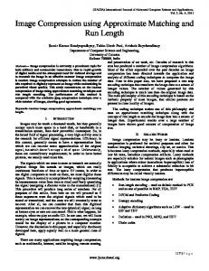
In the field of photogrammetry image data provides the basic information used to precisely locate and identify points being important to reconstruct the object of interest or to find the relations to the camera system utilised to take the images. The contribution of image processing here is powerful as long as points which have to be used to describe the object may be purely selected from image characteristics and don’t need to be specific ones. If selected points being placed in the object space have to be FIG. 1: PART OF SAMPLE IMAGE
296-223
-1-
tracks, where the space surrounding the tracks has to be checked for obstacles. This action has to be done continuously along the tracks for thousands of kilometres. For the German rail network does this mean, that some hundreds of thousands of obstacles have to be checked and surveyed. Accordingly an automated procedure has to be chosen in order to reduce the manual work load to the absolute minimum. The technical solution for the surveying is based on metric stereo images and uses photogrammetric algorithms for the calculation of the geometry of the obstacles found. Within these images the obstacles have to be identified and co-ordinated with respect to the camera co-ordinate system. Typically one finds only one or two obstacles in an image pair what leads to very few point measurements, because most of the obstacles (things projected from top or aside into the space above the tracks) are sufficiently
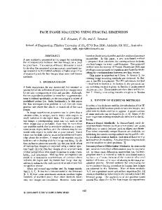
FIG. 2: SAMPLE TARGETS
recorded by two or three points. As these obstacles are of different nature and cannot be made visible by mounting of targets this measurement needs a lot of interpretative intelligence and therefore has to be performed by a human operator. Besides these few measurements of natural object points there are several other point measurements to be performed. These are necessary due to the fact, that the geometry of the obstacles has to be expressed with respect to the co-ordinate system of the railway tracks. This relation is physically realised by a frame of pass points which is mounted on a carriage moving on the tracks. On this frame 28 targets are mounted which are distributed in a space of 3m in either axis. Number and distribution of these points are necessary to meet the accuracy requirements (1-2 cm rms) . Finally, there are 9 grid crosses which have to be collected in each image. They express the relation to the camera coordinate system, allowing to transform the points in the digital image into the metric system of the camera. Taking the whole work load together we have in average a relation of 4 obstacle points to 37 reference points in each image. This clearly shows the need to find an automated solution for the detection and measurement of the signalised reference points. A most promising concept for an automated solution would be a knowledge based one, simulating the recognition and interpretation process of a human operator. Then all exterior influences affecting the appearance and the location of targets could be
296-223
-2-
incorporated into the model and would give a stable, reliable and precise software tool. However, this solution is beyond the state of the art of image analysis and knowledge engineering and might be realised in the future. But even without general knowledge based concepts a solution is possible if some geometrical constraints are existing. Such constraints reduce the variability of the appearance of the targets giving the opportunity to transform the knowledge about these constraints into geometrical conditions applicable to the image processing algorithms. THE SOLUTION The solution uses the estimated geometrical a priori knowledge about the geometries of the frame, the image and the camera, the position and orientation of the camera in the object space (exterior orientation) and the principal appearance of the targets (shape, size, geometry) [1]. However, in practice the appearance and the location of the targets in the images is affected by several external factors like, for example : distance image - target view angle illumination conditions background objects process of A/D conversion quality of exposure Correspondingly the target images vary in size, geometry, brightness, contrast and signal to noise ratio (cf. Fig. 2). The algorithmic conception therefore should allow to compensate for all of these degradations in order to provide a precise, stable and robust solution, running without any operator control. Looking in more detail to the tools of a possible solution one first has to have an algorithm allowing to identify and locate the targets in question. This algorithm is the core of the whole system and should be applicable to different target types, provide sub-pixel precision, has to be insensitive to degradations and should be tuneable in order to treat variations in the image content. In principle this might be achieved by two different set ups: a feature based and area based image processing. The first one extracts specific image contents like points or edges and is very useful if things which have to be extracted are well described by these elements. If one has complex objects or if the features are varying one has to invest a lot of effort to compose the basic elements to objects and to recognise and distinguish them from other ones [2]. The area based technique does not need any specific symbolic knowledge about the targets because this is implicitly expressed by the image information incorporated into the image window being used as reference in the matching process. This is of great value because it simplifies the algorithm. However, such a matching process fails, if the image information used deviates from the appearance of the real objects. It
therefore is necessary to find ways to realise such deviations and to modify the targets so that a correspondence to the real objects is possible. Within the actual application this is possible, because the general appearance of the targets is constant and known as the images come from one fix frame mounted on the carriage. For the algorithm remains the need to find a true and robust description of the real targets and to control the degradations which will primarily be found in terms of size, shape, brightness and contrast of the imaged target. With respect to the potential to produce accurate results area based matching meets all requirements. Using a least squares technique a theoretical precision of 0.1 pixel is possible [3] and likewise correlation based set ups will provide sub-pixel precision attaining 0.1 pixel under good conditions [4]. As a least squares solution needs good estimates for the transformation parameter it will be used in practice together with an image correlation process producing the estimates required. The benefit of the least squares then is to be found in a small further improvement of the accuracy [5][6]. In the actual application we do it without least squares.
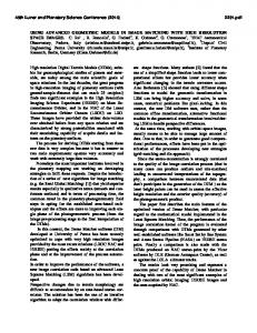
preparatory functions and generates the synthetic target patterns and all multi-scale representations necessary (cf. Fig.4). The second one locates the grid crosses (step 3-6) and the last one detects the object targets (step 7-10). The hierarchical structure using multi-scale representations of the input images primarily solves the task to speed up the calculations and reduces the risk to locate wrong patterns. Using the highest resolution the search process for each grid cross could lead in the worst case to approximately 10.000 different position which have to be checked for the cross pattern. With the multiscale concept this is reduced 6%. Considering the degrading effects they are treated by the solution as follows: • Variations in brightness and contrast are eliminated by the matching function, which expresses the cross correlation between reference and search window. • Contributions of background information are reduced by the chosen window size.
1. Generation of synthetic reference targets 2. Generation of multiscale representations of image and targets
FIG. 4: A MULTI-SCALE REPRESENTATION OF A REFERENCE TARGET
3. Search of grid crosses in a low resolution representation using wide search areas adopted to each individual cross location 4. Transformation of the crosses to the camera system with blunder check and quality control 5. Search of grid crosses in high resolution using narrow search areas adopted to the results of the previous search 6. Final transformation of the crosses to the camera system with blunder check and quality control 7. Search of object targets in a low resolution representation using wide search areas and a scale representation of the target adopted to each individual target location 8. Calculation of the exterior orientation with blunder check and quality control 9. Search of object targets in high resolution using narrow search areas and a scale representation of the target adopted to the results of the previous search 10. Final calculation of the exterior orientation with blunder check and quality control
•
Variations in size and shape of the targets are compensated by the multi-scale representation of the targets. Depending on the estimated geometrical relationship between image and object the target size can be calculated allowing to use an appropriate scale image. • Deformations due to the illumination conditions, which might lead to an appearing change of the target size are similarly compensated by the multi-scale representation by stepping up and down through the scale space. Finally, the numerical solutions for the transformation and orientation procedures are designed to detect wrong matches. This reduces the risk to get bad parameters which will affect the following algorithmic steps and could result in a failure of the whole procedure. RESULTS The performance of the algorithm will be documented in two ways. First, the results of a practical project with more than 200 image pairs are presented showing the reliability and precision of the located targets. Second, a comparison of results from manual target measurements and those acquired with the algorithm are shown and analysed.
FIG. 3: ALGORITHMIC STRATEGY
Using the area based image correlation technique as central tool for the location of the image patterns, the whole solution looks as outlined in Fig. 3. It consists of three parts for each image. The first one (step 1-2) has
296-223
-3-
Practical Project This test demonstrates the practical use of the algorithm, which meanwhile is in daily use for the monitoring of the tracks of the German railway company Deutsche Bahn AG. The algorithm is integrated in a software package
FIG. 7: TRANSFORMATION TO GRID POINTS (standard deviation of residuals at grid points) 0,0200 0,0180
left x left y
0,0160
right x right y
0,0140 std. dev. [mm]
distributed by Metronom, Mainz, which is used for the whole surveying and data collection process with respect to the detection of obstacles. The data set used here consists of more than 200 image pairs documenting the different practical conditions, ranging from good exposured daylight images over fairly exposed twilight images up to partly strong irradiated night images (cf. Fig. 5).
0,0120 0,0100 0,0080 0,0060 0,0040 0,0020 0,0000 1
2
3
4
5
6
7
8
9
point
FIG. 5: PART OF A DAYLIGHT AND A NIGHT IMAGE SAMPLE
In total each image may have 9 grid crosses and 28 target points exposed. For twilight or night images the number of exposed crosses is reduced to 4 or 5, because only 4 crosses are synthetically illuminated. Reliability As reliability measure serves the success rate for the location of crosses or targets and the amount of project failures where the number of points found lies below the absolute minimum of points necessary for the geometrical orientations. The success rate is very high. For daylight images except of one in all cases the crosses were found correctly. Even for images with bad illumination all exposed crosses were found. Likewise the success rate for object targets is comparable high. There are only few images where not all targets could be located. Primarily this is the case for twilight images, where the low illumination caused a few mismatches. FIG. 6: LOCATED POINTS 30 maximum possible 25
Precision for grid targets There are several accuracy measures usable for the verification of the achieved geometrical quality. This are the standard deviation of the transformation of the located grid points to the camera system, the remaining residuals and their behaviour over the large number of image pairs. As we want to concentrate on positional accuracy of the algorithm we have to suppress influences coming from degradations in the image geometry as for example expressed in the residuals or the standard deviation of the transformation. We therefore take a look at the standard deviation of the residuals calculated over all left or right images in the pairs. Assumed the geometric degradations in the images are constant this gives a good message about the reproducibility. Fig. 7 shows the standard deviations for the residuals. As can be seen there, the average varies between 2 and 4 µm what is equivalent 0.2 and 0.3 Pixel. Some grid points show greater deviations, documenting that these points are not exposed homogeneously. Precision for object targets As evaluation criteria for the accuracy of the object targets serves the results of the determination of the exterior orientation. Within this calculation process differences in the identification of the targets become visible. Correspondingly contradictions between the calculated object co-ordinates and the true ones show up for those targets serving as pass points.
grid points left image
FIG. 8: BUNDLE ADJUSTMENT WITH OBJECT POINTS (standard deviation)
grid points right image 20
N
object targets left image 0,0200
object targets right image
15
10
0,0150 std. dev. [mm]
maximum possible
5 required minimum
0 1
26
51
76
101
126
151
176
201
226
251 0,0050
image pair
Accordingly the amount of failures is negligible. There exists only one image out of 562 where the targets could not be detected in the required amount. This was due to problems with the image data and was not in the responsibility of the algorithm.
296-223
0,0100
-4-
0,0000 1
6
11
16
21
26
31
36
41
image pair
Fig. 8 shows the standard deviation of the adjustment for several models and confirms the impression achieved for the grid crosses. Most of the models have a standard
deviation of approximately 2-3 µm. However, beginning with image pair 30 the values rise. With this model the night images in this data set start leading to the conclusion, that the strong irradiation caused by the flashes affects the achievable precision to a certain amount.
to be found, documenting the different recognition processes for the individual operators. operator c
FIG. 11: DIFFERENCES AT OBJECT POINTS
operator d operator f operator h matching
0,8000
FIG. 9: BUNDLE ADJUSTMENT WITH OBJECT POINTS (residuals in x)
0,6000
0,0200
0,4000
mean (left image) std. dev. (left image)
33
31
29
27
25
23
21
19
17
15
13
9
11
7
5
-0,2000
0,0100 residuals [mm]
0,0000
3
Pixel
0,0150
1
0,2000
mean (right image) std. dev. (right image)
-0,4000 0,0050
-0,6000 -0,8000
0,0000 1
3
5
7
9
11
13
15
17
19
21
23
25
point
27
-0,0050
CONCLUSION -0,0100 point
This is confirmed if one looks at the targets themselves. Fig. 9 and Fig. 10 are displaying the squared residuals on a point base. Taking all image pairs into consideration points 11-22 show a good precision whereas point 1-10 vary stronger. This effect decreases when only daylight image pairs are treated. However individual points still have a bit lower accuracy. It therefore seems that the effect of illumination is superimposed by a point related one. Nevertheless, the level of accuracy is with an average of 0.2 Pixel still very high. FIG. 10: BUNDLE ADJUSTMENT WITH OBJECT POINTS (x-residuals at located targets, daylight images)
The practical example presented documents the possibility to avoid knowledge based solutions for the interpretative task of a human operator needed for a reliable process of point measurements if some conditions are met. The reliability of the algorithm is equivalent to human work and the precision is not less than the human one. REFERENCES [1] Boochs F., Heinz G.: Vollautomatische Orientierung digitaler Messbilder in einem terrestrischen Anwendungsfall, DGPF-Publications, 1998, Vol. 6, pp. 287-295.
0,0200 mean (left image) std.dev. (left image) mean (right image) std.dev. (right image)
0,0150
[2] Gülch E.: From Control Points to Control Structures for Absolute Orientation and Aerial Triangulation in Digital Photogrammetry, Zeitschrift für Photogrammetrie und Fernerkundung, 1995, Vol. 63, No. 3, pp. 130-136.
residuals [mm]
0,0100
0,0050
[3] Grün A.: Least Squares Matching: A Fundamental Measurement Algorithm, from Atkinson: Close Range Photogrammetry and Machine Vision, Whittless Publ., 1996, pp. 217-255.
0,0000 1
3
5
7
9
11
13
15
17
19
21
23
25
27
-0,0050
-0,0100 target
A final comparison of matching results with manual measurements serves as further proof. 4 different image pairs have been measured by 8 different operators allowing to differentiate between individual influences coming from the operator and contributions of the type of image pair. The results are as to be expected. There is no detectable difference between the quality of the manual measurements and those generated by the matching algorithm (cf. Fig. 11). Looking at the influence of the illumination there is a dependence visible in the human results. In case of daylight images stronger variations are
296-223
-5-
[4] Boochs, F., Hartfiel, P.: Festigung von Sicherheit und Zuverlässigkeit der DHM-Bestimmung bei Einsatz der Bildkorrelation, Bildmessung und Luftbildwesen, 1989, Vol.57, Nr. 3. [5] Höhle J. The Automatic Measurement of Targets, Photogrammetrie, Fernerkundugn und Geoinformatik, Vol. 1997, No. 1, pp. 13-22. [6] Schickler W.: Ein operationelles Verfahren zur automatischen inneren Orientierung von Luftbildern Zeitschrift für Photogrammetrie und Fernerkundung, 1995, Vol. 63, No. 3, pp. 115-122.