Home
Search
Collections
Journals
About
Contact us
My IOPscience
Precision patterning of PDMS membranes and applications
This article has been downloaded from IOPscience. Please scroll down to see the full text article. 2008 J. Micromech. Microeng. 18 037004 (http://iopscience.iop.org/0960-1317/18/3/037004) View the table of contents for this issue, or go to the journal homepage for more
Download details: IP Address: 128.100.48.213 The article was downloaded on 07/10/2010 at 23:29
Please note that terms and conditions apply.
IOP PUBLISHING
JOURNAL OF MICROMECHANICS AND MICROENGINEERING
doi:10.1088/0960-1317/18/3/037004
J. Micromech. Microeng. 18 (2008) 037004 (5pp)
NOTE
Precision patterning of PDMS membranes and applications Jianhua Tong, Craig A Simmons and Yu Sun Department of Mechanical and Industrial Engineering, University of Toronto, ON M5S 3G8, Canada E-mail:
[email protected]
Received 6 December 2007, in final form 9 January 2008 Published 6 February 2008 Online at stacks.iop.org/JMM/18/037004 Abstract This paper presents a method for precision patterning of polydimethylsiloxane (PDMS) membranes based on parylene C lift-off. The process permits the construction of PDMS membranes either with a highly flat, uniform top surface or with a controlled curvature. Effects of varying processing parameters on the geometrical characteristics of the PDMS membranes are described. The paper also demonstrates the application of the PDMS precision patterning method to the construction of PDMS microlens arrays, which require curved top surfaces, and a 3-axis electrostatic positioning stage that uses PDMS membranes with flat surfaces as a bonding material as well as a precisely defined spacer. (Some figures in this article are in colour only in the electronic version)
optical, chemical or plasma means. Although adding photo initiators can facilitate patterning [7], limitations include long exposure time, risks of coating photolithographic masks and deteriorated mechanical properties (e.g., poor reproducibility of modulus). Without initiator addition, previously reported methods for PDMS membrane patterning typically employ blade scratching [8] or bond-detach lithography [9]. Blade scratching produces membranes with a significant recess in the center [8]. Bond-detach lithography uses a patterned PDMS stamp to bond to a PDMS membrane. Due to adhesion, when the stamp is peeled away, the PDMS membrane is torn along the stamp edges and thus pattern is transferred to the membrane [9]. This method can result in rugged edges and broken membranes, and imposes stringent processing and peeling requirements. Inspired by a recent demonstration of protein patterning [10], we present a method based on parylene C lift-off for precisely patterning PDMS membranes. The approach permits the fabrication of PDMS membranes with a minimum thickness of 4 µm and a minimum width of 5 µm. The fabrication process also allows for the control of the surfaces of PDMS membranes to be either flat or semispherical like. Effects from varying processing parameters on geometrical characteristics of PDMS membranes are discussed. Finally,
1. Introduction Polydimethylsiloxane (PDMS) elastomer has become an important member in the repertoire of materials for MEMS and microfluidic device construction for its elasticity, optical transparency and biocompatibility [1, 2]. Two-dimensional and three-dimensional PDMS structures can be constructed through the well-established soft lithography technique [3, 4]. After the fabrication of PDMS structures, they are typically transferred and bonded to a substrate to form a device. Due to their elastic property and low Young’s modulus values (∼0.75 MPa with a 1:10 mixing ratio) [5], PDMS structures can function as an active mechanical component in MEMS devices. For example, a soft-lithographic lift-off and grafting process was developed to assemble a separately fabricated PDMS component onto a silicon structure to form a multi-axis motion stage, in which the elastic bending of PDMS flexural microjoints couples the in-plane motion produced by the Si comb drives to the out-of-plane direction [6]. MEMS development can also benefit from precision patterning of thin PDMS membranes without an assembly step, such as using PDMS membranes as a wafer bonding material, etch masks or an elastic mechanical component. However, patterning PDMS membranes below tens of microns is challenging. PDMS is inert, making it difficult to pattern using 0960-1317/08/037004+05$30.00
1
© 2008 IOP Publishing Ltd
Printed in the UK
J. Micromech. Microeng. 18 (2008) 037004 (a)
Note
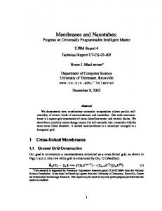
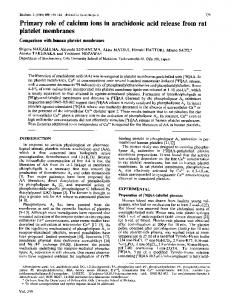
PDMS pre-polymer is mixed at a base solution to curing agent ratio of 10:1. After bubble removal in a vacuum desiccator, the pre-polymer is spun on the patterned parylene C layer (Figure 1(b)). The PDMS pre-polymer is partial cured, and then the parylene C layer is peeled off, leaving patterned PDMS membranes on the substrate (Figure 1(c)). The example PDMS structures shown in figures 1(d) and (e) are 15 µm in thickness. Although a high spinning speed produces thinner PDMS membranes, directly using a high spinning speed was unable to produce a highly uniform PDMS layer. Thus, we spin PDMS pre-polymer at 500 rpm for 30 s to allow the pre-polymer to fully cover the substrate and patterned parylene C layer, and use a spinning speed equal to half of the target top speed (3000–6000 rpm) for 30 s. PDMS pre-polymer is then spun at the target top speed for 60 s to reach the required thickness, and finally spinning is slowed down at a deceleration of 100 r s−2 . This spinning recipe yields a thin PDMS layer with a high degree of uniformity. This uniform PDMS pre-polymer layer must be partially cured before the underlying parylene C layer is peeled away. The degree of edge rounding (i.e., vertical sharpness) of patterned PDMS membranes can be tuned by varying curing temperatures and/or time. In our processing, for PDMS membranes from 4 µm to 20 µm thickness, the curing temperature is fixed at 80 ◦ C, and curing time is varied. With a short curing time (less than 20 s), the liquidity of PDMS pre-polymer is high. Thus, PDMS pre-polymer at edges flows downward, making the edges of the final PDMS membranes thinner than the center area, as shown by focusing differences in figure 2(a). A curing time between 20 s and 35 s reduces the liquidity of PDMS pre-polymer, tunes the curvature of the top surface and increases vertical sharpness, as shown in figure 2(b). An even longer curing time (35–45 s) makes the edges of PDMS membranes strongly adhere to the edges of the underlying parylene C, resulting in undesired satellite features (Figure 2(c)). Besides spinning speeds, varying the thickness of the sacrificial parylene C layer can also be used to tune PDMS membrane thickness. Note that PDMS membrane thickness is not always larger than that of the parylene C layer. When the width of parylene C trench openings is ∼3 times larger than the thickness of the parylene C layer, the resulting PDMS membranes are always thicker than the sacrificial parylene C layer. The thickness of the resulting PDMS membranes is T = Tp + Ts , where Tp is the thickness of parylene C
(d)
(b)
(e) (c)
Figure 1. Precision patterning of PDMS membranes. (a) RIE pattern LPCVD parylene C. (b) PDMS spin coating. (c) Peeling away parylene C. (d), (e) Patterned PDMS membrane examples (15 µm thickness).
the application of patterned PDMS membranes in microlens fabrication and wafer bonding and packaging for the construction of a 3-axis positioning stage is described.
2. Fabrication of PDMS membranes The fabrication process is illustrated in figure 1. A layer of parylene C is first deposited using LPCVD. Positive photoresist SPR220-7 is spun on top of the parylene C layer and UV patterned to form an etch mask for parylene C dry etching. After the parylene C layer is baked at 95 ◦ C for 1 h, it is RIE patterned using O2 plasma, as illustrated in figure 1(a). The residual photoresist is removed using acetone, and the sample is baked in an oven at 60 ◦ C for 10 min for moisture removal. In our processing, a 5–15 µm thickness parylene C layer is used. The tensile strength of a parylene C layer thinner than 5 µm is too low to warrant successful peeling. Rapid photoresist development immediately after UV exposure is also important to prevent sporadic detachment of parylene C from the substrate. Otherwise, undesired parylene C detachment can occur a couple of minutes after UV exposure of photoresist due to stress build-up. Sporadic spots of detached parylene C cause bubbles during subsequent RIE etching.
(a)
(b)
(c)
Figure 2. Optical microscopy pictures of patterned PDMS membranes with 50 µm bottom diameter under different partial curing times. (a) 10 s, (b) 25 s, (c) 40 s. 2
J. Micromech. Microeng. 18 (2008) 037004
Note
µ
(a)
(b)
(c)
(d)
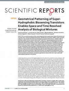
Figure 3. (a) Schematic of PDMS pre-polymer reflow. (b) 3D optical profilometer measurement of PDMS microlenses. Partial curing time: 0 s, α = 7.9◦ . (c) SEM picture of a microlens array. (d) SEM picture of the cross section of a PDMS microlens. Partial curing time: 10 s, α = 22.5◦ .
and Ts is determined by spinning speed. However, when the width of parylene C trench openings is smaller than 3 times of its own thickness, PDMS pre-polymer on top of the trenches is often taken away during parylene C peeling. Only PDMS pre-polymer in the trench bottom remains on the substrate, resulting in PDMS membranes thinner than the sacrificial parylene C layer. The thinnest PDMS membranes that this method can repeatedly produce are ∼4 µm thickness (slightly lower than the minimum thickness of sacrificial parylene C).
(a)
(b)
3. Application examples 3.1. Microlens arrays Microlenses are important components in optical data interconnects and MEMS-based microscopy imaging. Several microfabrication processes have been developed for the production of microlens arrays. Popovic et al [11] developed a method to produce microlens arrays using photoresist reflow. The refractive index and optical transparency were limited by the properties of AZ4620 photoresist. Zhang et al [12] presented a PMMA microlens fabrication process using an etched glass master. Similarly, a soft replica molding method [13] and a water droplet method [14] were also reported. However, assembly of microlens arrays is usually required. In this section, we demonstrate the application of PDMS membrane patterning based on parylene C lift-off to the construction of PDMS microlens arrays on a glass substrate without an assembly step. A maximum spinning speed ranging from 3000–6000 rpm is used to control PDMS membrane thickness. The curvature of the microlenses is controlled by adjusting PDMS partial curing time. In experiments, a partial curing time from 0 s to 20 s was used to adjust the flowing extent of PDMS
Figure 4. Optical profilometer measurement results of PDMS membrane top surfaces. (a) PDMS membrane produced using parylene C lift-off. (b) PDMS membrane produced using blade scratching.
pre-polymer to form a desired surface profile. Accordingly, the angle between substrate surface and vertical tangent of microlens borderline (Figure 3(a)) can be tuned. A longer partial curing time results in a larger angle. After partial curing, PDMS membranes are patterned by peeling away sacrificial parylene C. The samples are then baked at 200 ◦ C for 5 min to form PDMS microlens arrays. Figure 3(b) shows a 3D optical profilometry image of PDMS microlenses. The bottom diameter of the microlens is 137 µm, 3
J. Micromech. Microeng. 18 (2008) 037004
Note
(a)
(b)
(c)
(d )
(e)
Figure 5. A 3-axis positioning stage with patterned PDMS membranes used as a bonding material and as a precisely defined spacer. (a) Lift-off patterning of Au/Cr and PDMS membrane patterning according to figure 1. (b) DRIE etch top thin silicon wafer to form suspended structures. (c) Device picture of PDMS membranes and bottom electrodes. (d) A completed device 3-axis positioning stage. (e) A 15 µm gap between stage and substrate. (a)
(b)
(c)
Figure 6. (a), (b) In-plane (x–y) displacements versus actuation voltage squared. Also shown are coupling displacements along un-actuated directions. (c) Out-of-plane displacements before pull-in versus actuation voltages.
and the maximum height is 5.52 µm. These microlenses were fabricated with a maximum spinning speed of 5500 rpm and partial curing time of 0 s. Due to PDMS reflow, the thickness of the membrane changes from 15 µm to 5.52 µm. As the refractive index of PDMS in air is 1.43 ± 0.05 (580 nm) [15], the focal length of the microlenses in air was calculated to be 1.06 mm. Figure 3(c) shows a SEM picture of the PDMS microlens array on a glass substrate. Figure 3(d) shows the cross-sectional view of a microlens with a focal length of
0.84 mm (255 µm bottom diameter and 20 µm maximum height), which was fabricated with a maximum spinning speed of 5000 rpm and partial curing time of 10 s. The parylene C lift-off approach permits the creation of microlenses with a bottom diameter ranging from 5 µm to several centimeters with different focal lengths. PDMS microlens arrays can be directly fabricated on a silicon or glass substrate. As the transmittance of PDMS is ∼95% over a large frequency range [16], PDMS microlenses promise applications 4
J. Micromech. Microeng. 18 (2008) 037004
Note
in optics and photonics. Since no extra assembly is required, PDMS microlenses can be readily integrated into MEMS devices (e.g., microfluidic structures) for imaging purposes.
1.06 mm and 0.84 mm were demonstrated. PDMS membranes with a highly flat surface provide an effective, low cost solution for bonding substrates (Si–Si or Si–glass). For the construction of 3D MEMS devices, PDMS membranes can also serve as a precisely defined spacer.
3.2. Wafer bonding and packaging The PDMS patterning process is also capable of producing PDMS membranes with a highly flat and uniform top surface. Figure 4 shows profilometer measurement results of two PDMS membranes (2 mm by 2 mm squares). The top figure shows a membrane fabricated using the parylene C lift-off method, and the bottom shows a membrane produced by blade scratching. A height difference within 0.8 µm from center to edge was achieved, which compares favorably with the surfaces produced by blade scratching (center recess can be as large as 12 µm) when a flat surface is desired. The highly flat and uniform top surface making these PDMS membranes ideal structures for wafer bonding and function as precisely defined spacers for forming 3D devices. As an application example, a 3-axis electrostatic positioning stage was fabricated. The fabrication process is shown in figure 5. On an oxidized Si substrate, Au/Cr electrodes were formed by e-beam evaporation and lift-off. A 9 µm thickness parylene C layer was deposited and RIE patterned using O2 plasma. PDMS pre-polymer was spun onto the palylene C layer (maximum spinning speed: 5500 rpm), resulting in 15 µm thickness PDMS membranes. For partially curing PDMS, the substrate was baked at 80 ◦ C for 25 s. PDMS was then patterned by peeling away parylene C. After baking at 200 ◦ C for 5 min, the PDMS membranes with flat top surfaces were treated by O2 plasma and then were press bonded onto a thin Si wafer (130 µm thickness). The bonded sandwich was baked at 95 ◦ C for 30 min to increase bonding strength, and permanent bonding was formed. On the thin Si wafer, Au/Cr electrodes were formed as top electrodes of a parallel-plate actuator for z-axis positioning. Finally, the thin Si wafer was DRIE etched to form in-plane comb-drive actuators for x–y positioning (figure 5(b)). Device pictures are shown in figure 5(c)–(e). Testing results of decoupled 3-axis positioning are shown in figure 6.
References [1] Weibel D B, DiLuzio W R and Whitesides G M 2007 Microfabrication meets microbiology Nature Rev. Microbiol. 5 209–18 [2] Xia Y and Whitesides G M 1998 Soft lithography Angew. Chem. Int. Ed. 37 550–75 [3] Duffy D C, Schueller O J A, Brittain S T and Whitesides G M 1999 Rapid prototyping of microfluidic switches in poly (dimethyl siloxane) and their actuation by electro-osmotic flow J. Micromech. Microeng. 9 211–7 [4] Jo B-H, Van Lerberghe L M, Motsegood K M and Beebe D J 2000 Three-dimensional micro-channel fabrication in polydimethylsiloxane (PDMS) elastomer J. Microelectromech. Syst. 9 76–81 [5] Armani D and Liu C 1999 Re-configurable fluid circuits by PDMS elastomer micromachining 12th Int. Conf. on MEMS (Orlando, FL, 1999) pp 222–7 [6] Tung Y-C and Kurabayashi K 2005 A single-layer PDMS-on-silicon hybrid microactuator with multi-axis out-of-plane motion capabilities: II. Fabrication and characterization J. Microelectromech. Syst. 14 548–57 [7] Zhang W Y, Labukas J P and Ferguson G S 2005 Novel room-temperature first-level packaging process for microscale devices Sensors Actuators A 123–124 646–54 [8] Ryu K S, Wang X, Shaikh K and Liu C 2004 A method for precision patterning of silicone elastomer and its applications J. Microelectromech. Syst. 13 568–75 [9] Thangawng A L, Swartz M A, Glucksberg M R and Ruoff R S 2007 Bond-detach lithography: a method for micro/nanolithography by precision PDMS patterning Small 3 132–8 [10] Atsuta K, Suzuki H and Takeuchi S 2007 A parylene lift-off process with microfluidic channels for selective protein patterning J. Micromech. Microeng. 17 496–500 [11] Popovic Z D, Sprague R A and Connell G A N 1988 Technique for monolithic fabrication of microlens arrays Appl. Opt. 27 1281–4 [12] Zhang P, Londe G, Sung J, Johnson E, Lee M and Cho H J 2007 Microlens fabrication using an etched glass master Microsyst. Technol. 13 339–42 [13] Kuo J-N, Hsieh C-C, Yang S-Y and Lee G-B 2007 An SU-8 microlens array fabricated by soft replica molding for cell counting applications J. Micromech. Microeng. 17 693–9 [14] Chao S-H, Carlson R and Meldrum D 2007 PDMS microlens array fabrication using water droplets The 11th Int. Conf. on Miniaturized Systems for Chemistry and Life Sciences, µTAS 2007 (Paris, France, 2007) pp 1717–9 [15] Cardenas-Valencia A M, Dlutowski J, Fries D and Langebrake L 2006 Spectrometric determination of the refractive index of optical wave guiding materials used in lab-on-a-chip applications Appl. Spectrosc. 60 322–9 [16] Chang-Yen D A, Eich R K and Gale B K 2005 A monolithic PDMS waveguide system fabricated using soft-lithography techniques IEEE J. Lightwave Technol. 23 2088–93
4. Conclusion A PDMS membrane patterning method is presented. PDMS membranes are patterned using parylene C lift-off. The process allows precision patterning of PDMS membranes and permits control of PDMS membrane thickness and top surface profile. Key processing parameters are PDMS spinning speed, parylene C deposition thickness and PDMS partial curing temperature/time. PDMS microlens arrays and a 3axis positioning stage were constructed as applications of PDMS membrane patterning. Having a controlled curvature of top surfaces, PDMS microlens arrays with a focal length of
5