Missing:
Preserving Sharp Edges with Volume Clipping M. A. Termeer1 , J. Oliv´an Besc´os2 and A.C. Telea3 1
Institute of Computer Graphics and Algorithms, TU Wien, Austria 2 Philips Medical Systems, Best, The Netherlands 3 Department of Computer Science and Mathematics, TU Eindhoven, The Netherlands
Abstract Volume clipping is a useful aid for exploring volumetric datasets. To maximize the effectiveness of this technique, the clipping geometry should be flexibly specified and the resulting images should not contain artifacts due to the clipping techniques. We present an improvement to an existing illumination model for volume clipping to allow sharp edges in the data to stay visible. These sharp edges often originate from material transitions in the volume or structures being partially cut by the clipping geometry. The focus is on high, industrial image quality and flexibility of the algorithm; techniques for using high-resolution polygonal meshes as clipping algorithms and removal of artifacts are presented. Features of the latest consumer graphics hardware are exploited to provide the visualization at an interactive framerate without the need for multipassing. We have validated the techniques presented here by implementing them in the context of a professional volume rendering application at Philips Medical Systems, and comparing our results with current results produced by existing solutions.
1
Introduction
In clinical environments, Direct Volume Rendering (DVR) requires a high image quality, flexibility and performance in order to become more widely accepted as the visualization method of choice. While providing excellent anatomical context, current implementations often lack a good combination of the aforementioned requirements. Intensive research is being directed at image quality and performance. Conversely, very flexible solutions for DVR are often not capable to provide the utmost quality finetuned, more specific ones deliver. An important tool for exploring medical datasets is volume clipping. This applies for example to
imaging the coronary arteries. The complex geometry of these small vessels surrounding the heart can be perfectly visualized by DVR. By visualizing a large part of the coronary artery tree in a single image, detection of stenosis is accelerated. However, the human heart is surrounded by many other smaller structures often occluding the view. Volume clipping provides an effective way of removing these occluding structures. Since the clipping geometry should fit tightly around the heart for good results, support for complex clipping geometry is essential. While solutions for volume clipping using complex clipping geometries have been suggested, image quality was not up to the required level in any of the presented models. This often leads to distracting artifacts in the visualizations or a misinterpretation of structures. We present a number of improvements to current volume clipping solutions to attack this problem. First, we present an improvement to an existing illumination model for volume clipping that gives a better representation of sharp edges in the data, in combination with a high quality GPUbased ray casting volume rendering solution. Second, we prove that quality of GPU-based ray casting of volume data, both with and without clipping techniques applied, can be significantly improved by stochastic ray shifting. Finally we present an analysis of our solution, identifying shortcomings in branching behavior of current graphics hardware. The organization of this paper is as follows. Section 2 gives a brief overview of related work in volume clipping and GPU-based ray casting of volume data. Section 3 describes our improvements to the volume clipping techniques. Section 4 explains our ray casting approach and its characteristics. In section 5 we propose the use of stochastic ray shifting for improved image quality. Section 6 evaluates the performance and quality of our solution. A conclusion is given in section 7.
2
Related Work
Weiskopf et al. presented a technique for highquality volume clipping [12] capable of using any polygonal mesh, possibly concave, as a clipping geometry. Their solution focuses on using the rasterization capabilities of graphics hardware to cause a minimal overhead to the volume rendering. They also present an illumination model that takes the surface of the clipping geometry into account. To prevent discontinuities in lighting, they propose to “impregnate” the gradient of the clipping geometry along a small layer of constant thickness along the boundary thereof. While originally targeted at slicebased volume rendering, their solution extends well to a ray casting-based volume rendering solution. The recent advances in graphics hardware development have led to a more flexible and fully programmable accelerated graphics pipeline. It has been proved that current consumer graphics hardware is well capable of performing volume rendering by ray casting [9, 6]. This approach relies on fragment shader functionality and threedimensional texturing capabilities. A major advantage of such a ray casting based approach to volume rendering is that it produces images of high quality, is flexible in that it combines well with many existing extensions and is relatively easy to implement. Recent further improvements in graphics hardware have lead to the development of solutions performing the volume rendering by ray casting in a single pass [5, 11].
3
High Quality Volume Clipping
An advanced volume clipping technique designed for use on consumer graphics hardware was presented by Weiskopf et al. [12]. Various approaches were presented there, which all have in common that they somehow extract the depth-structure of the clipping geometry and use it to determine the visible parts of the volume. The most versatile technique to extract depth information from a polygonal mesh using graphics hardware is the depth-peeling algorithm [3]. The depth-peeling algorithm is a multi-pass algorithm that uses a second depth-buffer to store the depth-information of the previous pass. It is a variation of the dual depth-buffer technique [1]. The second depth buffer is used to cull any fragments that
were rendered in any of the previous passes, effectively “peeling off” a depth-layer each pass. The combination of all depth buffers forms the depth structure of the clipping geometry.
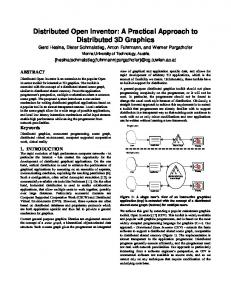
Figure 1: Intersecting depth-structures to yield volume probing (left) or cutting (right); the part of the volume that is to be rendered is colored gray. Once the depth structure of the clipping geometry is available, volume clipping is easily combined with ray casting-based volume rendering. As can be seen in Figure 1, the depth information controls which part of the viewing ray should be rendered and allows for both volume cutting and probing. A naive implementation of volume clipping introduces problems with the illumination near the edges of the clipping geometry. Near the edge of the clipping geometry, the gradient of the volume data may exhibit unwanted behavior due to the exposure of homogeneous regions in the volume. In these regions, the volume gradient has a very small magnitude and is primarily dominated by small variations or noise in the volume data. Moreover, the volume gradient most likely does not reflect the surface structure of the clipping object. The obvious solution is to use the gradient of the clipping object near the edge of this object. It can easily be extracted and stored during the depth peeling process. The gradient information is usually only required for the first depth-layer, as the illumination of the remaining layers commonly contributes very little to the final image. The most intuitive approach to use the gradient of the clipping object into the visualization is to “impregnate” the gradient along the edge of the clipping object. Note that this differs slightly from the technique proposed by Weiskopf et al. [12], where the interpolation of illumination terms is proposed. Since illumination terms are non-linear, we prefer to interpolate gradients instead. After the intersection
with the clipping object, a weighted combination of both the gradient of the clipping object and that of the volume is used along a fixed distance, usually a few voxels. The distance to the clipping object is generally not available, but using the distance to the last intersection along the viewing ray is a suitable approximation and does normally not lead to visible artifacts.
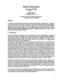
Figure 2: Gradient impregnation along a fixedwidth layer (top) and gradient magnitude guided gradient impregnation (bottom) on the engine dataset with a phantom clipping object. Material transitions can cause steep changes in the volume data. If the two different corresponding data values are mapped to significantly different opacities, this results in a visible hard edge between the two materials. If such a transition is cut by the clipping geometry, i.e. the hard edge is intersecting the edge of the clipping geometry, the linear interpolation of the two gradients causes an incorrect illumination of the edge. In Figure 2 (top) the edges appears to be rounded due to the incorrect illumination, while they are in fact a hard edges. Using a stepwise weighting function would cause the impregnation layer to become visible due to the discontinuity in the gradient, which is even less preferable. We give a simple but effective solution to the
above problem. The hard edge is caused by a steep change in opacity, due to a difference in value of the volume data. In this area of change, there is a well defined and well behaving gradient in the volume data. In order to apply the gradient impregnation only in the areas where needed, the homogeneous areas in the volume with a near-zero gradient, an accumulated gradient magnitude can be computed during the volume rendering. As soon as this accumulated volume gradient magnitude has exceeded a predefined threshold, the gradient impregnation is disabled (up to the next intersection with the clipping object). The threshold should be proportional to the small variations in gradient in homogeneous regions of the volume data. This effectively causes the gradient impregnation layer thickness to be controlled by the gradient magnitudes in the corresponding areas, instead of using a fixed layer thickness.
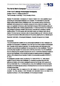
Figure 3: Effectively disabling gradient impregnation at regions with a high gradient magnitude. The lighter shape represents a region in the volume data with a significantly different value than its surroundings. The dark slab represents the gradient impregnation layer. A schematic overview of our idea is sketched in Figure 3. Note that the lighter shape inside the figure need not necessarily be mapped to a different opacity than its surroundings. Looking from the viewpoint, the gradient impregnation is effectively disabled after a change in volume gradient, as described earlier. In figure 3 the gradient impregnation has a uniform thickness, but variations in the volume data may indeed cause the thickness of the layer to vary over the volume as well. Most common is however the case shown in figure 3; steep
changes in volume gradient cause the threshold to be exceeded and thus gradient impregnation to be disabled, or small variations in the volume data cause the layer to have a more or less constant thickness. Figure 2 (bottom) shows the result of our idea; both the clipped edge and the remaining part of the volume have correct illumination. Note that discontinuities in the gradient may occur due to this approach in transitions between regions with different intensities. These discontinuities are however justified by the sudden change in surface normal. Here the difference in opacity was made large for illustrative purposes, but our solution also works for less large differences and even equal opacities.
4
Ray Casting Volume Data
We integrated the volume clipping technique from the previous section with a GPU-based ray casting volume rendering approach. The choice for ray casting was based on the fact that the method produces images of high quality, is very flexible and is easy to implement. We use standard direct volume rendering with a constant step size, front-to-back accumulation and a Phong-Blinn lighting model. We also implemented early ray termination by using the dynamic branching capabilities of current graphics hardware. The effect of this on the performance is described in section 6. As ray casting on the GPU has been described before [5, 11], we only mention the novel elements of our approach.
4.1
ture one could apply the depth peeling algorithm to account for occluded empty regions. The technique integrates well with the volume clipping. In fact, both the volume clipping and the empty space skipping algorithms, either used with depth peeling or not, result in a list of ray segments to be rendered. Intersecting these lists can be done using simple fragment operations and is very efficient.
Empty space skipping
To accelerate the rendering process, we use an empty-space skipping technique that is based on computing a tight bounding mesh of the volume data based on the current transfer function. Similar techniques for empty space skipping have been presented before [10, 7]. A major advantage of this approach is that it can be efficiently implemented on graphics hardware. The polygonal mesh can be rasterized, exploiting the rasterization capabilities of the graphics hardware, and the resulting depth-buffer can be used to compute the start and end points of each ray. For most practical cases, rendering two passes, one with the front-most faces and one with the back-most faces, is sufficient. For a more accurate depth struc-
(a)
(b)
(c)
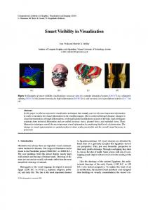
Figure 4: The empty-space skipping geometry; without optimization (a); hidden edges removed (b); tightly fit (c). The bounding mesh is constructed from a collection of bricks, typically 3x3x3 voxels. A brick is only part of the mesh if it contains at least one voxel that is not completely transparent according to the current transfer function. This would lead to a bounding mesh as depicted in Figure 4a. Removing shared edges between bricks, as depicted in Figure 4b, greatly reduces the number of faces in the mesh without changing functionality. Fitting the mesh more tightly around the volume, as shown in Figure 4c, leads to a more efficient empty space skipping structure. However, this may cause neighboring bricks to become disconnected, so care should be taken when combining the techniques of Figures 4b and 4c. The resulting structure is an efficient empty space skipping technique that causes very little overhead. During the volume rendering it requires only two texture lookups to retrieve the information required to alter the ray segment.
5
Stochastic Ray Shifting
Like many others, our implementation of DVR is a discrete sampling based attempt to approximate the volume rendering integral. The number of samples
taken during ray traversal controls the quality of the approximation of the integral and thus image quality.
(a)
effect on the human visual system than regular ones. The technique is similar to error diffusion used in e.g. printers to enhance image quality. Figure 5b shows the effect of adding a uniformly random offset of at most half the sampling distance to the entry point of each viewing ray. A practical result is shown in Figure 6c, showing indeed a much improved image quality. Note that as the resolution of the image increases, the noise becomes less visible. By combining both pre-integration and ray shifting we obtain Figure 6d; clearly a much higher quality while using the same sampling rate as Figure 6a.
(b)
Figure 5: Schematic occurrence of slicing artifacts (a); effect of adding noise to entry-points (b). Typical artifacts that occur when using a low sampling rate are slicing artifacts, also called ringing artifacts or staircase artifacts. Figure 6a shows an example occurrence of this unwanted behavior. This kind of artifact is most visible near regions with a sudden change in opacity. The effect is that the aliasing of the entry point in the more-opaque region becomes visible. Figure 5a gives a schematic view of this principle. A common approach to reducing the visibility of these artifacts is to use pre-integrated volume rendering [2]. This technique aims at approximating the volume rendering integral with a piecewise linear function instead of a piecewise constant function, gaining continuity. We have successfully integrated this technique in our volume rendering solution. A downside of pre-integrated volume rendering is that the look-up table needs to be recomputed whenever the transfer function is changed. Note that this also holds for the empty-space skipping geometry described earlier. Although pre-integration improves overall image quality, the slicing artifacts still occur, but are less clearly visible. This is demonstrated in Figure 6b. A different solution is to shift the entry points along a viewing ray by half the sampling distance compared to each of the four neighboring pixels [4, 8]. This solution dramatically reduces the visibility of the artifact in question by destroying the regular spatial arrangement of the slices. The use of a random pattern is also suggested and is clearly preferable. Many other areas where similar patterns are used, such as super-sampling schemes, have shown that random patterns have a better masking
6
Results
Figure 7 shows some results of our novel approach to illuminating clipped regions. Figures (a) and (b) demonstrate that our technique makes it possible to discriminate regions that are cut by the clipping geometry, while the traditional approach does not. Note that due to correct lighting the complicated surface structure can also still be perceived. Figures (c) and (d) show that the sharp edges allow for a much better perception of holes along the clipped surface. Note the bumped structure of the clipped surface; this is caused by the complex clipping geometry. While the sharp edges around the holes seem to be rounded with the traditional approach, their sharpness is clearly perceived with our improvement. Overall it can be seen that the technique allows for an improved perception of structures within the data along the edges of the clipping geometry. We implemented our solution using OpenGL 2.0 and the OpenGL Shading Language (GLSL). The use of assembly language for shaders was avoided to maximize compatibility among different graphics cards and driver versions as well as to have a more efficient implementation process. Our result is a versatile ray casting based volume rendering implementation that produces high-quality renderings. A limitation of the current implementation is that the maximum size of the volume is bounded by 128 megabytes. This restriction is caused by the video drivers and will probably change in the near future. For a more robust handling of large volumes, a technique using volume bricking can be used. The empty-space skipping and the early ray termination have both proved to be effective performance optimizations. The workload per fragment
(a)
(b)
(c)
(d)
Figure 6: Slicing artifacts occurring while rendering part of a human skull (a); improved quality by preintegration (b); improved quality by noise masking (c); both techniques combined (d). Note that for all figures the same sampling rate was used (approximately one sample each voxel).
(a)
(b)
(c)
(d)
Figure 7: Discriminating regions that intersect the clipping geometry in an extreme blowup of a heart rendering ((a) & (b)); A better perception of holes while clipping the engine dataset with the Stanford bunny ((c) & (d)).
Figure 8: Computational load of fragments mapped to a light (low) to dark (high) gradient.
is massively reduced in most cases. For the most situations however, a small amount of fragments requires much computation. One can think of highly transparent areas or the edges of the empty-space skipping geometry. In the latter case fragments of empty space are traversed. This takes a relatively
large amount of computation since the ray is not terminated by early ray termination. An example of this is shown in Figure 8, where the workload per fragment was mapped to a light (low) to dark (high) gradient in the rendering of a human skull. In some areas, the cubic structure of the empty-space skipping geometry is clearly visible in that the edges of the “surfaces” are surrounded by a dark rim. Due to the way dynamic branching is handled by the nVidia GeForce 6 and 7 series, the fragments with a high workload cause the processing of many other fragments with a low workload to be stalled. Thus a lot of time is spent on computing a relatively small portion of the image. This causes strange behavior sometimes; zooming in on an image may hide empty (and thus uninteresting) areas of an image. If these areas caused a high workload, a sudden increase in performance, as much as a factor of five, is observed.
1.2e5
rendering time
1e5
8e4
6e4
4e4
2e4
0
0
coherent random random multipass 0.2
0.4
0.6
0.8
1
ratio low/high workload fragments
Figure 9: Dynamic branching performance on an nVidia GeForce 6800 GPU.
The non-linear performance behavior or dynamic branching is shown in Figure 9. The first graph (coherent) shows the rendering time of a scene with two kinds of fragments; one kind has a low workload and the other a high workload. The ratio between the two kinds of fragments is mapped on the horizontal axis. The graph where the two kinds of fragments are spatially coherent clearly shows a staircasing behavior; a small amount of highworkload fragments causes an entire block to be stalled. As the ratio increases, the high-workload fragments span more blocks. The second graph (random), where the two kinds of fragments are spread randomly across the image, shows a near constant behavior. Due to the random distribution, each block is polluted with highworkload fragments and thus processing of lowworkload fragments is stalled. Kruger and Westermann proposed to use the early Z-test for implementing early ray termination [6]. This approach could also be used to group fragments of similar workload into two passes. However, this approach is shown to fail in the third graph (random multipass). The early Z-test is only effective if the fragments that need to be culled are spatially coherent. At the lower ratio, the early Z-test fails to cull any fragments and the scene is effectively rendered twice. As the ratio approaches one, the performance increases; the majority of the fragments are of one kind and thus the fragments with a high workload are more spatially coherent. This causes the effectiveness of the early Z-to increase and the performance converges to that of the singlepass approach. These results show that it is difficult to solve the problems related to dynamic branching behavior on the given architecture of the graphics hard-
ware. However, dynamic branching on graphics hardware is still in its infancy and the ongoing development of hardware will result in better performance. For example, the latest graphics board from ATi, the Radeon X1800 series, is claimed to have a smaller block processing size precisely targeted at solving this problem. A test board was not available to us, but predictions are that the implemented volume rendering algorithm performs significantly better on this graphics board due to the improved dynamic branching handling features.
Table 1: Rendering performance. Dataset Engine CT Skull CT Heart
Dimension
Coverage
Fps
2
49%
12.5
2
57%
3.52
2
98%
6.17
256 x110 512 x173 512 x150
Table 1 shows an overview of the performance of our solution on images of 5122 pixels. The third column indicates the image coverage; the amount of pixels for which the fragment shader was instantiated. Of course it is not possible to give a single performance figure for the algorithm, as the performance is heavily dependent on the transfer function and sampling rate. Thus samples-per-second would be a better performance measure, but is hard to measure. Due to the excellent performance-quality trade-off offered by the slicing artifact masking, any performance measurement depends on the required quality. As the focus was on high-quality, settings were used such that further increase of the sampling rate yielded no visible improvement in image quality. The performance overhead caused by the volume clipping, including our contribution of novel illumination techniques, was not significant while using polygonal meshes of up to 70,000 polygons with two depth layers. The main reason for this is that rasterization of polygonal meshes is much faster than volume rendering on current graphics hardware.
7
Conclusion
We have presented an improvement to an earlier illumination model for volume clipping [12] that is
capable of dealing with sharp edges in the volume data. It thus allows for a much better perception of complicated structures along the clipping geometry by preserving the visibility of material or tissue transitions in semi-transparent regions. The technique is independent of opacity mappings used for the data. We proved that this technique can be successfully integrated with single pass ray casting of volume data on graphics hardware. Second, we presented that a significant quality improvement can be obtained by using a combination of pre-integrated rendering and stochastic ray shifting. The latter technique destroys the local coherency of deviations from the volume rendering the human perceptual system is so sensitive to. Finally, we present a quantitative and qualitative evaluation of the proposed volume rendering solution and show that high-quality visualizations can be produced at interactive framerates. We have validated the techniques presented here by implementing them in the context of a professional volume rendering application at Philips Medical Systems, and comparing our results with current results produced by existing solutions. The performance is hard to compare to that of other volume rendering solutions targeting similar hardware, since not all also employ volume clipping techniques or produce similar quality. Our general impression is however, that slice-based rendering is not as flexible, versatile, high-quality, and easy to implement as a pure ray casting solution. Overall we believe that ray casting is a serious competitor to slice-based DVR. Current limitations of the presented solution include the inability to handle very large volumes, but these could be overcome by using a GPU-focused caching algorithm using multiple textures. Further quality improvements may be achieved by exploring the combination with frequency domain volume rendering or by using dynamic sampling rates. Furthermore it has been shown that GPU-based ray casting allows for a wide variety of visualization techniques [11].
Acknowledgement This work has been funded by Philips Medical Systems in the scope of the COMRADE project.
References [1] Paul J. Diefenbach. Pipeline Rendering: Interaction and Realism through HardwareBased Multi-Pass Rendering. PhD thesis, University of Pennsylvania, 1996. [2] Klaus Engel, Martin Kraus, and Thomas Ertl. High-quality pre-integrated volume rendering using hardware-accelerated pixel shading. In Proc. ACM HWWS ’01. ACM Press, 2001. [3] Cass Everitt. Interactive order-independent transparency. nVidia Corporation, 2001. [4] Alexander Keller and Wolfgang Heidrich. Interleaved sampling. In Proc. Rendering Techniques ’01, pages 269–276, 2001. [5] T. Klein, M. Strengert, S. Stegmaier, and T. Ertl. Exploiting frame-to-frame coherence for accelerating high-quality volume raycasting ongraphics hardware. In Proc. IEEE Visualization ’05, pages 223–230, 2005. [6] J. Kruger and R. Westermann. Acceleration techniques for gpu-based volume rendering. In Proc. IEEE Visualization ’03, 2003. [7] Warren Leung, Neophytos Neophytou, and Klaus Mueller. Simd-aware ray-casting. In Proc. Volume Graphics ’06, 2006. [8] Benjamin Mora, Jean-Pierre Jessel, and Ren´e Caubet. A new object-order ray-casting algorithm. In Proc. IEEE Visualization ’02. IEEE CS Press, 2002. [9] Stefan Roettger, Stefan Guthe, Daniel Weiskopf, Thomas Ertl, and Wolfgang Strasser. Smart hardware-accelerated volume rendering. In Proc. VISSYM ’03, pages 231–238. Eurographics Association, 2003. [10] Lisa M. Sobierajski and Ricardo S. Avila. A hardware acceleration method for volumetric ray tracing. In Proc. IEEE Visualization ’95, page 27. IEEE CS Press, 1995. [11] S. Stegmaier, M. Strengert, T. Klein, and T. Ertl. A simple and flexible volume rendering framework for graphics-hardware–based raycasting. In Proc. Workshop on Volume Graphics ’05, pages 187–195, 2005. [12] Daniel Weiskopf, Klaus Engel, and Thomas Ertl. Interactive clipping techniques for texture-based volume visualization and volume shading. In IEEE TVCG, volume 9, pages 298–312, 2003.