Primal-Sketch Feature Extraction from a Log-Polar Images
Recommend Documents
their discriminatory ability in correct classifying images as either belong- ing to contractions or ... an efficient feature extraction methodology based on anisotropic image process- ..... diagno-sis using online learning and differential evolution.
is used for the noise suppression. Index Termsâ Edge detection, feature extraction, image pro- cessing, multiresolution, noise suppression, wavelet transform.
1,3School of Computer Engineering, Nanyang Technological University, Singapore ... This paper presents a method for motion recovery from monocular images.
various regions of interest with the help of Skin color segmentation technique, Thresholding, knowledge based technique for face recognition. Keywords: Skin ...
based on Colour Image Segmentation and Skeletonization ... image segmentation algorithm, a crust extraction algorithm and our new skeleton extraction ...
Email: [email protected]. KEYWORDS: Feature Extraction, MATLAB, ANN, Land use, Land cover. ABSTRACT: Feature extraction is the most important ...
Keywords: oil palm in vitro shoots, machine vision, feature extraction, thresholding, image processing. Date received: 20 May 2009; Sent for revision: 30 June ...
This paper examines the issue of direct extraction of low level features from ... is in compressed form for efficient storage and transmission, it is important.
Abstract. The extraction of a representative set of features has always been a challenging research topic in image analysis. This interest is even more important ...
AbstractâFeature extraction is one of the most important phases of medical image classification which requires extensive domain knowledge. Convolutional ...
Available Online at www.jgrcs.info ... image feature extraction approach that is used to predict oral ... order to automatically extract those features Registration.
global landmarks and ridge pattern characteristics. The commonly used global fingerprint features .... to find the optimal registration. The direct application of eq.
AbstractâColor retinal photography is an important tool to de- tect the evidence of various eye diseases. Novel methods to extract the main features in color ...
extraction of global and local features in fingerprint images. A global feature ... taneously able to extract local ridge orientation, ridge frequency and ridge qual-.
paper, we first give a short review of these methods proposed for text detection and recognition in web images; then a framework to extract from web images is ...
We propose to tackle the problem using a model based on marked point ... MPP framework has been defined on the space of arbitrarily-shaped objects allowing more accurate extraction ..... Then, a level set segmentation is performed in order to refine
In cardiac imaging, echocardiography (cardiac ultrasound) is the simplest, low-cost, and highly ... However, these images are known to have low signal-to-noise ratio, low ... echocardiography images for the registration of multi-view real-time .... t
Dec 25, 2001 - filtering techniques applied on satellite images to enhance point and line .... Following paragraph illustrates the GM Solutions software and it's ...
Jun 20, 2018 - Keywords: propagating filter; hyperspectral image; spectral-spatial ... of the edge-preserving properties of bilateral filtering and guided filtering.
Nov 10, 2014 - NDVI and NDWI technique based on DWT and SVD ... image processing to improve visualization features presented in the image. It plays a ...
Step 4: Convert the Original image and the Source image to ycbcr Color Space. .... [4] http://www.dca.fee.unicamp.br/DIPcourse / html-dip/c4/s12/front-page.html.
1 Illustration of Robert Hill system for retinal scanning. Blood vessel forms in the retina, is unequaled to each and every iris image. Retina is one of the reliable ...
on extracting the topology statistics within the local surface sampled at ... are key-points that provide identification of surface anatomy forms between and.
Primal-Sketch Feature Extraction from a Log-Polar Images
We present a novel approach 1 for extracting primal sketch features (edges, ... Traditional image feature extraction operators have usually been designed by ...
Primal-Sketch Feature Extraction from a Log-Polar Images Herman M. Gomes Departamento de Sistemas e Computa¸ca˜o, Universidade Federal da Para´ıba, Av. Apr´ıgio Veloso s/n, 58109-970 Campina Grande, PB, Brazil [email protected] Robert B. Fisher Division of Informatics, Edinburgh University 5 Forrest Hill, Edinburgh EH1 2QL, UK [email protected] Abstract 1
We present a novel approach for extracting primal sketch features (edges, bars, blobs and ends) from a log-polar image. Symmetry operators and a PCA pre-processing module precede a set of neural networks that learn the feature’s class and contrast. Experiments show the process accurately extracts the desired feature-based image description.
Keywords: primal sketch, log-polar, neural networks, principal component analysis
1
Introduction
Traditional image feature extraction operators have usually been designed by hand and act on Cartesian images (an artifact of the sensor architecture). However, the organisation of the primate visual system seems to be quite different and we can use this to produce interesting results in artificial vision systems. The mapping from the retina to the visual cortex can be mathematically approximated by a log-polar representation (Schwartz (1977)). This transforms rotation and scaling in the Cartesian domain into translation in the log-polar domain and can reduce the complexity involved when recognising objects at different scales and orientations. Moreover, the representation is space-variant, i.e., there is a high resolution centre surrounded by a progressively lower resolution periphery, allowing a more compact representation for the image data. There are several examples in the literature of vision systems that take advantage of log-polar images (e.g. Grove and Fisher (1996); Lim et al. (1997); Jurie (1999)). Similar image representations have been constructed from receptive fields modelled as multiple Gaussian derivative filters at a number of orientations and scales (Rao and Ballard (1995)). Our goal is to extract low level features in a retina-like (log-polar) representation using a different approach. The features (oriented edges, bars, ends and center-surrounded blobs) are based on the primal sketch hypothesis for the human visual system proposed by Marr (1982). Trying to manually build a model for completely describing the features could be error prone and present some difficulties because of the unusual sensor geometry and the receptive field integration at retinal level. Instead, learning the features was a more effective approach. A neural network based approach performs this task. An architecture designed to encode the feature’s class, position, orientation and contrast has been proposed and tested. Success depended on the incorporation of a function to normalise the feature’s orientation and a PCA pre-processing module to produce better separation in the feature space. 1 This work was supported by CNPq and DSC/COPIN/UFPB, Brazil. This is an extended version of a paper presented at SIBGRAPI’01 (Gomes and Fisher (2001)).
1
Neural network learning of edge features has already been discussed in the literature. Pham and Bayro-Corrochano (1992) used a concatenation of two perceptrons: one for noise filtering and another one for edge detection. The edge detection network was trained to recover a given edge component within a 3x3 window at 8 different orientations. The results showed that their approach presented a performance slightly inferior to that of the Sobel edge detector. In a more successful attempt, Chen et al. (1995) trained a neural network with synthetic data from a model of an ideal step edge. They found that their system had better noise tolerance than the Canny edge detector. A general difference between our work and the above approaches is that we have chosen a model which tries to extract interesting image descriptions inspired by the primate visual system. Most previous research used a Cartesian space whereas we detect features in the logpolar space. Moreover, our aim is to extract several features, in addition to edges, at different orientations and contrasts. Grove and Fisher (1996) extracted primal sketch features from a log-polar image, as in this paper, but used a set of logical operators instead of a learning based approach. The operators were manually defined as expressions involving the pixels of a 1-ring window of a center and six surrounding receptive fields and were applied throughout the log-polar image. One of the problems with the above approach is that operators are heuristically defined and, therefore, there is no guarantee that they will work well and that they will allow graceful degradation. Also, if a different window size or window shape was needed, it would be necessary to manually design new logical expressions for the operators, which can lead to mistakes.
2
Image Representation
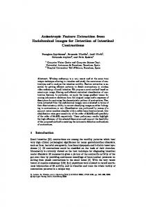
The image representation re-samples the input Cartesian image using a mask consisting of concentric rings of overlapping circular receptive fields, whose centres are geometrically spaced from the centre of the mask (see Fig. 1). The innermost region, named the fovea, contains a high density hexagonal receptive field grid. If we define an image that is accessed by using the rings (logarithm of the distance of the rings to the retina centre) and sectors of the outer retinal region, then we have a log-polar representation. We simulated a hexagonal packing outside the fovea by shifting each consecutive ring by half of the angle defining a sector of receptive fields. The radius of the nth outer retinal ring is: R(n) = β n R(0), where R(0) is the radius of the first ring exterior to the fovea and β defines the geometrical progression. Similarly, the radius r(n) of a particular receptive field in ring n is r(n) = β n r(0). We defined a 48 ring and *** sector retina with 60% overlapping and β ≈ 1.1, which covers a circular region of the input Cartesian image of about 256 pixels. Some examples of applying the above retinal mask to real images can be seen at the end of this paper. The output of a given receptive field of radius r is: X I(u + x, v + y)F (x, y) (1) O(u, v) = x2 +y 2 ≤r 2
where O(u, v) is the neuron output, I(x, y) is the perceived intensity and F (x, y) is the receptive field function (we used a normalised Gaussian with σ = ∗ ∗ ∗r). We designed a method for estimating the local surface reflectance information which is derived from the receptive field computation. By taking the logarithm of the intensities and assuming that I(x, y) = E(x, y) R(x, y), E is the irradiance falling on the object, and R is the local surface reflectance, we have: X log(R(u + x, v + y))F (x, y) (2) O0 (u, v) ∼ = log(E) + x2 +y 2 ≤r 2
The log(E) term in Eq. (2) is nearly constant over local image regions and therefore makes the receptive field computation O 0 a good approximation for the weighted logarithm of the reflectance. Since the architecture, described next, has linear pre-processing in the initial projection stage and the projection weights sum to approximately zero, then the projection of the log(E) terms in a
2
Figure 1: Retina structure. In order to enhance details, parameters different from those chosen in the experiments were used in this figure.
3
neighbourhood will also be approximately zero. Thus, the feature extraction is primarily based on the reflectance structure of the neighbourhood.
3
Feature Extraction
Features are trained and detected in a window of receptive fields composed of a central receptive field plus its next 6 and 12 surrounding neighbours, hexagonally distributed. The oriented features (edges, bars and ends) can appear at several distinct orientations: edges and ends are detected at 12 possible orientations; and bars at 6 possible orientations. For training purposes, synthetic exemplars of the features are drawn in a fixed position on the input image corresponding roughly to a particular window of receptive fields. Then, the output of these 19 receptive fields is orientation normalised, pre-processed via a PCA module and used as input to a set of neural network modules specialised to detect each of the features. The overall architecture is presented in Fig. 2, the individual processes and data are explained in subsequent sections. position Extract Recep. Field Windows
Input Images
orientation Normalise Orientation
Compute Projection
PCs
Edge Bar Blob End
Apply Neural Networks
NNs
Edge Bar Blob End
Compute Feature Planes position, feature class, orient., contrast Edge Feat. Bar Planes Blob End
Figure 2: System’s architecture: processes (rounded boxes) and data (rectangular).
3.1
Normalising the Feature Orientation
In order to reduce the number of principal components and to simplify the problem of learning the features, we initially normalise the receptive field windows into a standard orientation. To perform this task, we use a symmetry operator defined as a mask that associates negative weights to a subset of the receptive fields in the retinal window, and positive weights to the remaining receptive fields. By computing the convolution of the symmetry operator (defined at different orientations with respect to the central receptive field) and the input receptive field window, the detected orientation will be the one that maximises the absolute value of convolution. The last step consists of rotating the receptive field window to a standard orientation. The operator is applied at the 12 orientations defined by the receptive fields in the outer ring of the window, giving a resolution of 30o . There is a different symmetry operator for each of the oriented features. It is not necessary to know which feature type we have before normalising, as we normalise with the operators for all feature types and apply all the corresponding PCA and classification modules. More formally, the operator’s output for orientation θ is defined by: 2 6i X X Opfθ (n, s) = wθf (i, j) V (G(i, j, n, s)) (3) i=0 j=0 where f is the feature type: edge, bar or end; (n, s) are the global polar coordinates (ring, sector) for the central pixel of the receptive field window; wθf (i, j) is the operator’s weight (in a local polar coordinate system); G is a function that calculates the retinal image coordinates underneath each of the operator weights; and V is the receptive field value at a given retinal coordinate. The
4
1 weights at each position can be either + N1 or − M , where N + M =19, the number of receptive fields within the window (Fig. 3). We select the θ that maximises Eq. (3).
Figure 3: Symmetry operators. White circles represent a weight of N1 , and darker ones represent 1 a weight of − M . N and M are the number of white and dark circles within the operator’s mask, so that weights always sum to zero within any given mask.
3.2
Principal Component Analysis (PCA)
The training sets are decomposed into their eigenvalues and eigenvectors (or principal components, see Jackson (1991) for more details on PCA). One decomposition is obtained for each of the four feature type’s training sets (edge, bar, blob and end). We don’t distinguish between positive (+) and negative (−) contrast representations of features because the removal of the mean values leaves the two forms being the negative of each other. An unknown data sample named Y (in our case, a 19-receptive-field-window obtained from a test image) can be projected onto the set of principal components Vi by a simple matrix multiplication: Pi = Y 0 Vi . The resulting projection Pi represents that data sample in terms of the principal components for a given primal sketch feature class i. If a component of the projection Pi is large, then it suggests that our data is close to the pattern the eigenvector represents, and if we have a low valued projection the conclusion is the other way around. This projection is repeated for all classes i ∈ {edge, bar, blob, end}. PCA transforms the inputs that the neural network modules will receive. However, instead of using all 4x19 projections from the four feature classes, we combine subsets of the most representative principal components. We simply select the principal components associated with the largest eigenvalues (Jolliffe (1986)). However, we are not interested in components representing the average intensities of the input patterns (the very first components) because those would not help the process of spreading out the feature classes in the input space. From the above, the following principal components were kept: {2,3,4,5,6} for edge, bar and end; and {2, 3} for blob features. Thus the input to the neural modules is reduced to a vector of 17 elements.
3.3
Neural Network Architecture
Classification used MLP-backpropagation networks minimising a least square error metric, due to its simplicity and reasonable computational power. A total of seven neural networks were built, one for each of the seven feature classes: edge, +bar, −bar, +blob, −blob, +end, −end. Each network receives the results of the PCA pre-processing module (17 inputs) and has only 2 outputs: neuron ˜ representing the non-feature class. The hidden layer N representing the feature and neuron N has 9 neurons, about half of the size of the input layer. The contrast within a retinal window
5
is calculated according to the Eq. (4) (Bruce et al. (1996)). The desired output for a neuron representing a particular feature was represented in terms of this contrast: c=
|Lmax − Lmin | Lmax + Lmin
(4)
where Lmax and Lmin are the minimum and maximum intensities found in an image patch, respectively. We defined a classification rule that takes into account the strategy used during training: whenever a feature that should be recognised by a neural module is presented then the network ˜ ; if a is trained to output the feature’s contrast through neuron N , and zero through neuron N ˜ = 1. However, counter-example is presented, then neuron N should now output 0 and neuron N we need to be more tolerant when classifying untrained features, as the network outputs will not necessarily produce a sharp separation between feature and non-feature classes. To do this, our classification rule simply states that a module recognises a feature whenever its neuron N produces an output (the estimated contrast) that is above a classification threshold T HD (explained later) ˜. and also above the output of the other neuron N
4
Training and Evaluation
An initial training set was constructed from synthetically generated features. This seems to be a better approach than manually extracting and labelling lots of features from real images because a large number of feature variations can be easily computed. By assuming that the feature examples are chosen from a more descriptive set, this allows for a smaller training set to be used. After some initial experiments, we reached the conclusion that, although the synthetic training set was very useful, manual selection of a small set of features from real images was still required for achieving better results. Contrasts within the set ±{0.3, 0.4, 0.6, 0.8, 1.0} were used when drawing bars, blobs and ends. A negative contrast here means that the intensities in the feature background are higher than the ones in the feature itself. Edges were drawn using only positive contrasts, i.e. the intensities in the region above the feature orientation line are greater than the intensities in the lower region in order to avoid the generation of the same pattern twice as the feature orientations covers the whole circle. Fifteen different combinations of intensity were used in the generation of the contrasts for all of the features. One of the intensities was taken from the set {85, 170, 255} and the other was derived according to Eq. (4) to produce the desired contrast. Ends and edges were generated in steps of 30o at 12 different orientations in the range (0o , . . . , 330o ), while bars were generated only at 6 orientations in the range (0o , . . . , 150o ) due to symmetry reasons. Other sources of variability in the training sets were the “size” of the feature and the use of Gaussian additive noise. Blobs, bars and ends sizes were 0.6, 0.7 and 0.8 of the central receptive field diameter. Gaussian additive noise was added to the drawn features in order to broaden the training set. Random counter examples were generated in order to help the training process. These counter examples simulate unstructured input data and data from other low level features not considered in this work that are inevitably present in real images. Counter examples sets were also enriched with exemplars from the other feature classes. Table 1 contains some examples of the training features. We used a learning rate of 0.005, momentum of 0.95 and a neural module was considered trained when all the training patterns passed with a 0.1 error bound. On average, it took about one thousand epochs to train each module.
4.1
Evaluating the System’s Performance
The trained networks were tested with a set of unknown synthetic features produced by the same generators used to build the initial training sets, with the difference that now the features were 6
edge
+bar
-blob
+end
counter example not applicable
Cartesian inputs Retinal outputs
Table 1: Some examples of the training features. Differences in contrast between Cartesian inputs and retinal outputs are due to the logarithmic receptive field computation.
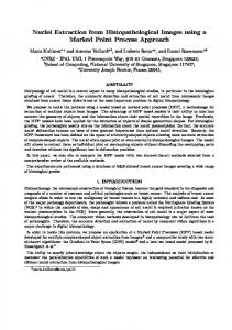
generated at arbitrary orientations. We generated 80 test exemplars per class by linearly varying the contrast from 0.21 to 1.0, with a step of 0.01 (-0.21 to -1.0, for negative features). The intensities used to produce the above contrasts were randomly chosen as well as the remaining parameters for orientation, Gaussian noise level and size. The next 83 patterns are counter examples (the first 40 were randomly generated and the remaining 43 were randomly chosen from other class examples). Figure 4 shows the actual network outputs of the edge classifier when fed with the synthetic testing data. All the other classifiers presented graphs very similar to that of the edge classifier. The oscillations along the network outputs for the testing sets are partially explained by the convergence error of 0.1 used during the training. The same applies to the small oscillations in the second half of the picture, corresponding to the networks response to counter-examples. Reducing the neural network convergence error could reduce the prediction errors during testing, but at the cost of a slower training and risk of overfitting, which could incur loss in generalisation. Another cause for the oscillations in the first half of the graph are the small prediction errors caused by the symmetry operators. We computed the absolute differences between real and estimated orientations when processing the feature’s through these operators and observed that the top errors were all under the operator’s resolution of 30 degrees, which is an indication of good performance. 1 0.9 0.8 0.7 0.6
Edge outputs
0.5 0.4 0.3
neuron feature neuron non-feature
0.2 0.1 0 0
20
40
60
80
100
120
140
160
Figure 4: Outputs from the trained edge neural module when applied to its synthetic testing set. The horizontal axis is the test image number, with 1-80 as true examples and 81-163 as non-exemplars. The vertical axis is the estimated contrast. The value of the threshold T HD (see Sec. 3.3) was chosen as the highest classification threshold that produces best overall performance. The reason for this is that we are not interested in 7
detecting very low contrast features. We varied the threshold from 0.0 to 1.0, in steps of 0.01, and measured the classification errors. From these experiments we observed that any threshold smaller than 0.15 is associated with the best overall performances (smallest classification errors) in all the networks.
4.2
Experimenting on Synthetic and Real Images
The final step of the approach is to enrich the training sets with features taken from real images. Initially, a set of real images was tested using the modules trained with synthetic features. Then, a small subset of these images was used as the source of additional manually selected training exemplars. The intensities used to compute the contrast of these new exemplars are estimated from their retinal outputs as if they were composed of uniform intensity patches in the Cartesian domain. Finally, the neural modules are re-trained with the improved training sets and tested over the same initial set of images. This process is repeated until the output of the extracted features is satisfactory. Preliminary experiments have shown that the addition of only a few exemplars of real features (typically 5-10) was enough to cause a visible reduction in the networks’ generalisation errors, see Fig. 6. In order to help the reader understand the outputs of the feature extraction architecture described in this paper and before applying it to any real images, which may contain complicated textures and features not easily spotted by the eye, a number of synthetic images were initially used, see Fig. 5. From a subjective evaluation, apart from some small uncertainty with regards to the feature location and smaller accuracy at the centre of the image, where the receptive field size is too small to match the feature’s size, it is possible to conclude that the classifiers are doing a reasonable job at detecting the features they have been designed for. It is possible to compare the results of the proposed and previous approaches when applied to the same real test image by looking at Figs. 6 and 7, respectively. We can see that the new approach brought a reasonable improvement to the feature extraction process not only with respect to accuracy (more features correctly extracted) but also to the enhanced quantisation of the contrast. Additional results on a second test image are given in Fig. 8.
5
Conclusions
A previous attempt by Grove and Fisher (1996) to extract primal sketch features achieved only partial success. Features were detected using a number of manually defined logical operators within a fixed retinal window, which, when applied to real images, failed to detect some low contrasting features as well as misclassified a number of others (Fig. 7). The approach presented in this paper takes advantage of the inherent learning from examples and generalisation properties of neural networks. This allowed the discovery of classification parameters tuned to the unusual log-polar architecture, with the result of much better performance. Our architecture contains seven independent neural network modules (connected only through the training sets, i.e. examples from one module used as counter-examples in the others), each one receiving inputs from a PCA pre-processing module, whose main purpose was to spread out the classes in the feature’s manifold. This novel arrangement presented better results with respect to the number of correctly classified features, provided a richer description for the image data with the addition of an estimate for the feature’s contrast, and became a more flexible solution to the problem in the sense that whenever a new feature class is required, only its training set needs to be provided. Primal sketch features obtained as discussed in this paper are being successfully used as image representations for the problem of learning structural relationships from sets of iconic (2D) object models obtained from a sequence of scenes (see Gomes and Fisher (2000) for further details).
8
Classifier
+Bar
Edge
-Blob
-End
Input image
Retinal image
Extracted features
Figure 5: Testing the classifiers on synthetic images. Only a small subset of the images and classifiers is shown. The extracted features row shows that the features were found well when the scale of the feature matched the scale of the receptive fields. Hence, some feature were not detected in the centre (features too large) and periphery (features too small).
References Bruce, V., Green, P., Georgeson, M., 1996. Visual Perception: Physiology, Psychology, and Ecology. Psychology Press. Chen, W., Thacker, N., Rockett, P., 1995. A neural network for probabilistic edge labelling trained with a step edge model. In: Proc. of 5th Int. Conf. on Image Processing and its Applications. pp. 618–621. Gomes, H., Fisher, R., 2000. Structural learning from iconic representations. Lecture Notes in Artificial Intelligence 1952, 399–408, Springer-Verlag. Gomes, H., Fisher, R., 2001. Learning and extracting primal-sketch features in a log-polar image representation. In: Proc. of Brazilian Symp. on Comp. Graphics and Image Processing. IEEE Computer Society, pp. 338–345. Grove, T., Fisher, R., 1996. Attention in iconic object matching. In: Proc. of British Machine Vision Conf. pp. 293–302. Jackson, J., 1991. A User’s Guide to Principal Components. John Wiley & Sons. Jolliffe, I., 1986. Principal Component Analysis. Springer-Verlag. Jurie, F., 1999. A new log-polar mapping for space variant imaging: application to face detection and tracking. Pattern Recognition 32, 865–875. Lim, F., West, G., Venkatesh, S., Dec 1997. Use of log polar space for foveation and feature recognition. IEE Proc. Vision, Image and Signal Proces. 144 (6), 323–331. Marr, D., 1982. Vision. W. H. Freeman and Co. Pham, D., Bayro-Corrochano, E., 1992. Neural networks for low-level image processing. In: Proc. of the IEE Int. Conf. on Artificial Neural Networks. pp. 809–812. Rao, R., Ballard, D., 1995. An active vision architecture based on iconic representations. Artificial Intelligence Journal 78, 461–505. Schwartz, E., 1977. Spatial mapping in primate sensory projection: analytic structure and relevance to perception. Biological Cybernetics 25, 181–194.
9
INPUT IMAGE
RETINAL IMAGE
EDGES
+BARS
+BLOBS
+ENDS
−BARS
−BLOBS
−ENDS
INPUT IMAGE
RETINAL IMAGE
EDGES
+BARS
+BLOBS
+ENDS
−BARS
−BLOBS
−ENDS
Figure 6: From top to bottom: results of our system on test image 1 after training with only synthetic features; and after adding a few manually extracted real features to the training sets.
10
INPUT IMAGE
RETINAL IMAGE
EDGES
+BARS
+BLOBS
+ENDS
−BARS
−BLOBS
−ENDS
Figure 7: Results from a previous approach proposed by Grove and Fisher (1996).