transient stability assessment (TSA) of power systems with high penetration of .... one group have a minimum of 360 degrees rotor angle difference with ...
> ACCEPTED VERSION OF THE PAPER
ACCEPTED VERSION OF THE PAPER < behaviour of each generator. In most of the above mentioned cases the instabilities related to specific generators or groups of generators as well as generator specific indices are not used. The other important aspect for the overall TSA, addressed in this paper, is the impact of network topology changes on system transient behaviour. This issue has been addressed to a certain extent in the past in systems with conventional generation in [19], [20] and [5] but not in systems with RES where this effect could be more pronounced. This paper, proposes a comprehensive probabilistic framework for TSA of systems with increased levels of penetration of RES over range of operating conditions and network topologies. The main motivation of the paper is to propose a probabilistic methodology that can be used to reflect changes and identify tendencies in the overall dynamic behaviour of power systems with increased penetration of RES and more importantly individual generators. The spatiotemporal variation of system dynamics due to the introduction of intermittent RES might cause local effects on individual generators which are more pronounced considering transient stability. The framework aims at informing decisions during the planning phase and therefore it is based on more accurate time domain simulations since computation time is not of great significance. The main contributions of the paper are the following: i) The effect of both wind generators and PhotoVoltaic (PV) units along with the displacement of synchronous generators and network topology changes, on transient stability of the overall system, is investigated. ii) The occurrence of system instability caused by specific generators or groups of generators losing synchronism with the system is identified using a hierarchical clustering approach. This opens the possibility of defining risk in a more elaborate manner. For example, instability due to one generator losing synchronism has a smaller impact than instability due to multiple generators losing synchronism. The identified generators or groups of generators prone to loss of synchronism could be “acted upon” at planning stage to improve the overall system transient stability by applying different stabilizing measures including the installation of devices to implement corrective control (such as dynamic braking, Flexible AC Transmission Systems, etc.), network reinforcements and design of appropriate control actions (such as intentional islanding, load shedding, generator tripping, etc.) [21]. iii) The probabilistic dynamic behaviour of each individual generator is identified by calculating several generator specific probabilistic indices. This can highlight different aspects of the effect of RES and network topology changes on the probabilistic behaviour of individual generators. iv) Statistical analysis along with the use of graphical methods of system wide and generator specific transient stability indices presented in the paper can provide input to development of special protection schemes [22] by providing either system specific or generator specific thresholds. This information can be used as additional measure to distinguish between stable and unstable contingencies. II. PROPOSED FRAMEWORK A probabilistic framework for transient stability assessment
2
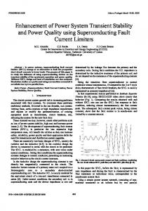
considering the uncertainties occurring in modern power systems is presented in Fig. 1. The use of data mining methods for the online identification of the dynamic behaviour of power systems usually requires the simulation of a large number of contingencies that are used in machine learning training procedures. Decision Trees (DTs) are one of the tools used for the online identification of the system behaviour after a disturbance, triggering corrective control actions as presented in [23]. This paper focuses on the offline procedure that utilizes the simulation data obtained from simulated disturbances during the training of DTs. The data from probabilistic Monte Carlo (MC) simulations can be used to characterize the system and individual generators’ dynamic behaviour. Critical generators/ groups
Monte Carlo dynamic simulations databse
System/generator specific probabilistic indices
Statistical analysis
Network planning, protection studies, risk assessment
Impact of RES, network topology
Fig. 1. Probabilistic Transient Stability Assessment framework.
A. Generation of Database of System Transient Responses A number of Ns MC simulations are performed following the procedure shown in Fig. 2. A power system dynamic model suitable for stability studies is required, taking into consideration the connected RES with the respective controllers. Since transient stability can be also significantly affected by pre-fault operating conditions, the uncertainties concerning system loading and wind/PV generation for a 24 hour period are considered. Moreover, the uncertainties of the fault location and duration are also accounted for. Only three phase faults are considered in this paper due to the fact that the three phase faults typically have strongest impact on system stability. Even though this might not be true for all systems, the proposed framework relies on time domain dynamic simulations without any restriction on the software/program used to perform them. Therefore, any type of contingency that can be simulated using state of the art software can be included in the database of transient responses. In a similar manner, since the proposed methodology relies on time domain RMS simulations, a variety of models for different power system components available in software packages can be used. For example, in this paper constant impedance load models are used for the cases studied but different load models (either static or dynamic) are readily available in most simulation software and can be easily used when performing the RMS simulations. Furthermore, the impact of RES connected to distribution network can be also taken into account following approaches available in the literature [24], [25] where aggregated dynamic models of distribution networks with non-synchronous generation are developed. These models can be easily implemented in power
> ACCEPTED VERSION OF THE PAPER < system simulation software and can be therefore used as part of the proposed methodology when performing the dynamic RMS simulations. All random variables are sampled according to appropriate probability distributions describing the uncertain parameter behaviour. The sampling of the respective distributions is performed separately for each load and each RES unit in the system to consider independent behaviour of loads and RES units. After the uncertainties in loading and RES contribution to power generation have been accounted for, an Optimal Power Flow (OPF) problem is solved to determine the output of conventional generators. The dispatch obtained from OPF also determines the amount of disconnection of conventional generation and consequently system inertia reduction due to increased RES penetration. The rotor angles of each generator are stored as the output of simulations and used to study the dynamic behaviour of the system in a probabilistic manner. The whole procedure is repeated for different network topologies and/or amount of connected RES to study the impact of network topology changes and RES penetration on transient stability. The proposed framework offers full flexibility when accounting for relevant uncertain parameters. The sampling of uncertain factors can be done according to any probability distribution based on historical data, prior knowledge or forecast [26] and solving the OPF problem can include any number of additional security constraints associated with RES, as proposed in [27]. Power system dynamic model Sampling of uncertainties Run OPF Conventional generation disconnection
Effect of conventional generation spare capacity
Monte Carlo simulations (Ns cases) Obtain rotor angles
Hierarchical clustering
Calculate Transient Stability Indices Statistical analysis
Critical generators/groups
Output of Probabilistic TSA
Fig. 2. Flowchart illustrating the proposed methodology.
B. Identifying and Clustering Critical Generators A hierarchical clustering method is applied to determine the groups of generators exhibiting instability in each simulated contingency. The agglomerative (bottom up) method is applied with a cut-off value of 360 degrees, since this is considered to be the transient stability limit. Euclidean distance between the data points is used as the similarity measure and complete linkage is chosen as the linkage criterion [23]. This results in groupings in which generators of one group have a minimum of 360 degrees rotor angle difference with generators of another group. Therefore,
3
hierarchical clustering is used to identify the unstable generators as well as the generator grouping patterns for each simulated contingency [23]. The percentage of cases that each generator is exhibiting instability (i.e. the probability of instability of each generator) is a measure of how stable each generator is. Critical generators and generator groups can be identified in this way. The impact of RES on transient stability can be investigated by observing changes in the probability of instability of the generators. The effect of added uncertainties and of the different dynamic behaviour of RES units on system stability is identified in this way. The impact of different network topologies on transient stability can be also identified in a similar manner. C. Transient Stability Indices Apart from ranking generators according to the number of instabilities observed, four stability indices are also calculated. Several indices to quantify the transient stability status of a system are available in the literature [28]-[31]. Composite indices based on transient energy conversion, rotor angle, speed and acceleration have been proposed in [29], [31]. In [30], frequency domain severity indices are introduced utilizing PMU measurements. In this paper, measurement based indices are chosen so that they can also be used as part of an online TSA. Multiple indices are used, to ensure comprehensiveness of the assessment [28] as variations of different indices can reveal different underlying causes that affect transient stability. System specific and generator specific tendencies are derived from statistical analysis of the indices. For example, for a given generator the probability to exhibit a certain value of an index (e.g. speed deviation) is calculated. This information can be used to define generator specific limits for special protection schemes [22]. The four indices used are common transient stability indices, which can also constitute the base of more complex indices [28]-[31], and are defined by (1)-(4). All the indices are calculated from the simulated rotor angle responses δig(t), where i=1…Ns is the number of simulated contingencies and g=1…Ng the number of generators. Transient Stability Index (TSI) is an index considering the stability of the whole system for a specific contingency [32]. Negative value of the TSI means that the case is unstable since the difference between rotor angles of at least two generators for the same time instance is more than 360 degrees. The rest of the indices are generator specific. The maximum rotor angle deviation, maximum speed deviation and maximum acceleration of each generator are calculated as shown in (2)-(4). In this study, the indices are mainly used in a comparative manner between generators as well as between different topologies to reveal tendencies considering the transient stability of the system. 360-δmax,i TSIi =100∙ (1) 360+δmax,i 0 Δδmax ig =max( |δig -δ | ) ig
(2)
> ACCEPTED VERSION OF THE PAPER < Δωmax ig = max(|Δωig (t)|) =max( | amax ig =max(|aig (t)|)=max( |
δig (t)-δig (t-Δt) |) 2πfΔt
ωig (t)-ωig (t-Δt) |) Δt
(3) (4)
where δmax,i is the maximum rotor angle deviation between any two generators in the system for the same time instance, δ0ig is the initial rotor angle of each generator, Δωig is the speed deviation and αig is the acceleration. Apart from the transient stability indices, an additional measure is used to identify the impact of conventional generation disconnection on transient stability of the system. When RES are connected, this will eventually lead to conventional generation disconnection. The generator spare capacity SCig, defined in (5), is a measure of the conventional generator loading which is an important parameter considering transient stability. Moreover, when spare capacity is kept low this means that in general more conventional generation will be disconnected leading also to lower system inertia. The effect of conventional generation spare capacity on transient stability is also investigated in this study. PSG,ig SCig =1(5) SSG,ig ∙pfSG,ig where PSG,ig is the power produced by each generator (determined by OPF), SSG,ig is the apparent power of each generator after considering any disconnection and pfSG,ig is the nominal power factor. D. Statistical Analysis Statistical analysis is important in order to draw conclusions and identify tendencies considering the dynamic behaviour of the system, from the abundance of available simulated data. Simple statistical measures considering central tendency, dispersion and correlation (e.g. mean value, standard deviation, etc.) can reveal certain tendencies but they do not adequately provide information for the whole range of values of the indices. Minimum/maximum value, first quartile, median and third quartile can be visualized using boxplots to provide an easy way to compare changes in indices (e.g. TSI) for different network topologies and connection of RES. On the other hand, plotting Cumulative Distribution Functions (CDFs) of the random variables (i.e. the transient stability indices) can reveal the associated probabilities for the whole range of values each index takes. Moreover, nonparametric/graphical methods, such as quantile-quantile plots are also used in this study to highlight changes in the probabilistic behaviour of the whole system and of specific generators. Quantile-quantile plots, are used to identify whether two sampled random variables come from the same Probability Distribution Function (PDF). In a quantile-quantile plot, the quantiles of an observed random variable from two separate samples are plotted against each other. If the samples fall on a straight line (i.e. y=x) this means the two samples come from the same distribution. Observing where the samples are placed
4
with respect to the straight line provides information considering the shape of the underlying PDFs for the whole range of values of the random variable [33]. This way, the similarities or differences for the whole range of an index between two different cases are investigated, highlighting the effect of topology changes and RES penetration on transient stability. The graphical method can be applied on any generator specific index to investigate the behaviour of each generator or on the TSI to study the behaviour of the whole system. For example, if the dynamic behaviour of a specific generator is affected by a topology change, this will be reflected in the quantile-quantile plot of the corresponding indices. In general, information from statistical analysis can be used to design special protection schemes [22], that take into consideration additional features based on measurements, i.e. some or all of the indices [34]. Protection device settings can be then tuned with specific values for groups of generators which could eventually reduce the number of false tripping and avoid spreading of local events. III. TEST SYSTEM AND CASE STUDIES The test network used, is a modified version of the IEEE 68 bus, 16 machine reduced order equivalent model of the New England Test System and the New York Power System (NETS – NYPS). The conventional part of the test network is adopted from [35], [36] and RES are added at the buses shown in Fig. 3. Two types of RES units are connected on each bus: Doubly Fed Induction Generators (DFIGs), representing wind generators and Full Converter Connected (FCC) units, representing both wind generators and PV units. The standard IEEE 68-bus, 16-generator test network is chosen in this paper since its dynamic behaviour has been extensively studied in the literature and therefore provides a good point of reference. Moreover, the network is reasonably large to reflect reduced order real power system models (e.g. GB equivalent network with 12 generators [37]). NEW ENGLAND TEST SYSTEM G7
NEW YORK POWER SYSTEM G3
G5 G4
G6 7
62 65
20
64 19
24
21 G9
66 67
68
29
51
34
33
L66
46
G15
55
25
15
30
27 26
45 35
61
L42
38
L43
11
L44
G11
54 L45
8 G8
49 31
42 10 G10
47 53
1
18
L71
32
37
28
L41 57
16
50
44
17
36
39
43
12
60
58 56
52 9
63
G16
G13 13
59
4 23
G12
2
5
6 22
G2
3
48
40
G14 L69
14
G1 41
Fig. 3. Modified IEEE 68 bus test network.
A. Components modelling The test network consists of 16 generators (G1-G16) in five interconnected areas. NETS consists of G1 to G9, NYPS of G10 to G13 and the three areas are represented by equivalent generators G14, G15 and G16, respectively. Standard 6 th order models are used for all synchronous generators. G1-G16 are equipped with either slow IEEE DC1A dc exciters or fast
> ACCEPTED VERSION OF THE PAPER < acting static exciters type IEEE ST1A and G9 is equipped with a Power System Stabilizer (PSS). All generators are also equipped with generic governors, representing gas, steam and hydro turbines. A generic type 3 model, suitable for large scale stability studies is used in this paper to represent DFIGs. The model has a structure similar to the one proposed by WECC [38] and IEC [39], as shown in Fig. 4 and is available in DIgSILENT – PowerFactory [40]. It takes into consideration the aerodynamic part and the shaft of the wind turbine/generator as well as the pitch control of the blades. The rotor side converter controller is also modeled including relevant limitations, ramp rates and protection mechanisms, such as the crowbar. The DFIG is represented by a typical 2nd order model of an induction machine neglecting the stator transients and including the mechanical equation [41]. The rotor side converter is controlling the voltage in the rotor as in [42]. Therefore, the model represents all the relevant parts that influence the dynamic behaviour of DFIGs. Similarly, a type 4 wind generator model is used to represent all FCC units. Both wind generators and PV units can be represented by a type 4 model in stability studies, since the converter can be considered to decouple the dynamics of the source on the dc part. This is also suggested by the WECC Renewable Energy Modeling Task Force [43], which develops a PV model by slightly modifying the type 4 wind generator model. The FCC model used in this paper and shown in Fig. 5 has a similar structure to [38], [39] and is available in the DIgSILENT – PowerFactory software [40]. Both DFIGs and FCC units are treated as aggregate units. Each RES unit model has a 2 MW power output and the number of connected units is varied to determine the output of the aggregate unit. Furthermore, all RES units are considered to have Fault Ride Through (FRT) capabilities and remain connected during the fault. The amount of connected RES for each area of the system, i.e. the installed capacity of RES, is given as a percentage of the total installed conventional generation capacity of that area before adding any RES. Considering the total RES installed capacity, approximately 66.67% are assumed to be DFIG wind generators and the remaining 33.33% are FCCs. FCCs are further considered to be 30% wind generators and 70% PV units. All dynamic simulations are RMS simulations and are performed using DIgSILENT – PowerFactory software [40]. Aerodynamic part
Speed reference
Pitch control
Turbine
Shaft
Speed Measurement
Turbine Power
Grid Interface
Reference signals
DFIG Rotor side converter control Rotor Voltage
Protection
Fig. 4. DFIG control structure.
Electrical Measurements
5
Reference signals Converter Controller Electrical Measurements
Controlled Voltage
Static Voltage Source
Grid Interface
Fig. 5. FCC unit control structure.
B. Modelling of uncertainties Daily loading and PV curves are initially used, obtained from national grid data [44] and from the literature [15], respectively. First, the hour of the day is sampled randomly following a uniform distribution to determine the pu values for all the loads and all PV units according to the respective curves. For every hour within the day, the corresponding uncertainties are also modeled using a normal distribution for the system load [26] and a beta distribution for the PV generation [45]. Therefore, an extra uncertainty scaling factor for loads and PVs is introduced which is eventually multiplied with the corresponding value from the daily loading or PV curve, respectively. The normal distribution for the system loading uncertainty has mean value 1 pu and standard deviation 3.33% and the beta distribution a and b parameters are 13.7 and 1.3 respectively [46]. For wind generation, the mean value of the wind speed within one day is considered constant [47], and the uncertainty of the wind speed is modelled using a Weibull distribution [48]. After considering the wind speed uncertainty, the power curve of a typical wind generator is used [49] to derive the power output. The total output of a wind farm is scaled according to the number of wind generators. The Weibull distribution parameters used are φ =11.1 and k=2.2 [48]. The aforementioned PDFs are sampled separately for each load and RES unit in the system in a similar manner to [50]. However, [50] deals only with the uncertainty of loads and not RES. This approach is followed to represent the variability of the uncertainties in a more realistic manner. After considering the uncertainties, OPF is solved to determine the conventional generators dispatch PSG,ig. The cost functions for OPF are taken from [26]. The nominal capacity of each generator SSG,ig is then adjusted by considering 15% spare capacity according to (5). In case the resulting SSG,ig from (5) is larger than the initial nominal power of the generators, it is set to that initial nominal value. This means that there is no room for conventional generation disconnection in this case. The disconnection of conventional generation due to both load variations and RES penetration is considered in the following way: Since the generators are considered as aggregated units, reducing the nominal power, is equivalent to a reduction in the moment of inertia of the power plant and an increase in the generator reactance. Only three phase self-clearing faults are considered in this study. However, the simulation database could be extended to include other contingencies as well. A uniform distribution is used to model the fault location which means that the fault may happen with equal probability at any line of the test network and at any point along the line. A normal distribution
> ACCEPTED VERSION OF THE PAPER < with mean value of 13 cycles and standard deviation 6.67% is used to model the fault duration [23]. C. Monte Carlo Simulations After considering all the uncertainties, Ns MC simulations are performed for each case, for different network topologies and amount of connected RES units. The number of simulations (Ns) is chosen by keeping the error of the sample mean up to 5%, for 99% confidence interval, considering the TSI as the random variable. The error of the sample mean is calculated using (6), where Φ-1 is the inverse Gaussian CDF with a mean of zero and standard deviation one, σ2 is the variance of the sampled random variable, δ is the confidence level (i.e. 0.01 for this study) and XN is the sampled random variable with N samples [51]. For this specific system (for all case studies considered) the number of required Monte Carlo simulations (Ns) to limit the error to 5% is 6000. δ σ2 (XN ) Φ-1 (1- ) √ 2 N eX̅N = XN
(6)
Five Test Cases (TCs) are presented in this section, consisting of 6000 simulations each (i.e. 30,000 simulations in total). In the base case (TC1) no line is disconnected and low amount of connected RES is considered. In TC2, all the RES units are disconnected and therefore the associated uncertainties are also not considered. TC3 and TC4 are the same as TC1 but lines 1 (between bus 21 and 68) and 2 (between bus 33 and 38) of NETS and NYPS are out of service, respectively. In TC5, high amount of RES is considered to be connected. TC2 and TC5 are used to study the impact of RES on transient stability, while TC3 and TC4 the impact of network topology changes. The lines set as out of service are chosen close to critical generators and groups of generators (ones that experience the instability most frequently) in the NETS and NYPS area, respectively. For the given TCs the error of the sample mean varies from 3.4% for TC5 up to 5% for TC3 for 99% confidence interval. The TCs are summarized in Table I. TABLE I NUMBER OF UNSTABLE CASES AND PATTERNS OBSERVED FOR TCS TCs RES installed capacity Lines out of service (% of system nominal capacity) 20% TC1 TC2 20% Line 1 TC3 20% Line 2 TC4 60% TC5
6
IV. RESULTS OF PROBABILISTIC TRANSIENT STABILITY ASSESSMENT
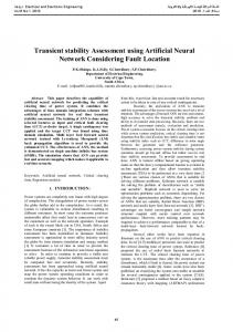
In general there are two main opposing effects which are analyzed in the following sections. On the one hand, the dynamic behaviour of RES might cause an improvement of transient stability and on the other hand the disconnection of conventional synchronous generation causes deterioration of transient stability. Moreover, the uncertain temporal and spatial availability of RES might cause more or less favorable operating conditions. These spatio-temporal changes, due to RES, in the dynamic behavior of power systems can affect locally the transient stability of individual generators. Therefore, investigating instabilities as well as the probabilistic dynamic behavior of individual generators, becomes even more significant. The results presented in this section highlight the additional information that can be obtained from the proposed methodology compared to previous methods of probabilistic TSA (e.g. instabilities related to specific generators/groups of generators, change in probabilistic dynamic behavior of indices related to individual generators, etc.). A. Critical generators The critical generators of the system are identified according to the number of times each generator becomes unstable. The number of cases each generator is exhibiting instability is identified using the hierarchical clustering approach presented in Section II B. Initially the grouping patterns are defined and afterwards the instabilities for each generator are observed, i.e. the number of cases each generator belongs to any unstable group. This means that for certain cases more than one generator might be unstable. In Fig. 6, the results for the probability of instability for each generator are shown, i.e. the number of instabilities divided by the total number of simulated cases for each TC. G9 and G11 are the most unstable generators in NETS and NYPS area, respectively. One of the reasons is that they are the ones having relatively smaller moment of inertia constant. In general, generators in the NETS area exhibit more instabilities than those in the NYPS and external areas. G9 has the highest probability of exhibiting instability for all cases, except from TC3 when disconnecting line 1 causes G6 and G7 to become more unstable. TC1 and TC4 do not exhibit significant differences. However, G11 becomes slightly more unstable because disconnecting line 2 in NYPS weakens that area of the network in a similar manner to the one described with TC3 and NETS area. G12-G15 do not exhibit any instabilities in the studied cases. Probability of instability (%)
8
All simulations are performed in DigSILENT/PowerFactory software using a computer with an Intel Core i7 3.4 GHz processor and 16 GB of RAM. For the TC without RES, approximately 18 hours are required to perform 6000 Monte Carlo simulations. For the TCs that include RES, approximately 60 hours are required for 6000 dynamic simulations.
7 6
TC1
5
TC2
4
TC3
3
TC4
2
TC5
1 0 G1
G2
G3
G4
G5
G6
G7
Generator number
Fig. 6. Unstable generators for all TCs.
G8
G9
G10
G11
> ACCEPTED VERSION OF THE PAPER
ACCEPTED VERSION OF THE PAPER < a) G1 G6 G9 G11 G15
1
0.5
0.5
0 0
0 0 400
200
50 600
0.5 0.029 0 0
0.04
0.02
Cumul. Prob.
1
0.14
0.12
0.1
0.08 0.06 Maximum speed deviation (pu) c)
0.5 0.194 0 0
8.
2200
2000
1800
0.038
CDFs
0.2
0.1 of
maximum
a)
rotor
0.429
angle
deviation,
C. Effect of RES and conventional generation disconnection on transient stability The effect of RES on transient stability is investigated in this section using the proposed methodology. In this study, all RES units are considered to have FRT capability. Therefore, the control logic followed by RES units when a disturbance happens is to increase the reactive power output to provide support to the system. In general, this operation can improve the transient stability of the system. However, the pre-fault operating conditions are also affected by the uncertainties introduced by RES, which can lead to either more or less favorable operating conditions for specific generators. Furthermore, the disconnection of conventional generation to account for the connection of RES tends to have a negative impact on transient stability, due to the reduction in inertia and nominal capacity of the synchronous generators. In Fig. 9a CDFs for the TSI for TC1 (low amount of connected RES), TC2 (no RES) and TC5 (high amount of connected RES) are presented. As explained in Section III B, the spare capacity of conventional synchronous generation is kept always constant at 15% (including TC2), which means that there is some generation disconnection considered even for this case due to load variations within the day. Relatively high spare capacity combined with FRT capability of RES leads to a reduction of the total number of instabilities in system with RES. This is reflected by observing the probability of the TSI to have a negative value which is 9.5% for TC5, 9.7% for TC1 and 12.9% for TC2. Moreover, TSI values above 55 tend to appear with smaller probability as the
b)
0.5
0.4
0.3 Maximum acceleration (pu) speed
deviation
and
c)
acceleration
for
TC1.
amount of RES increases. This indicates the occurrence of larger oscillations within the stable cases, especially for TC5. a)
1
Cumulative Probability
Cumul. Prob.
1
300
250 200 150 100 1600 1400 1200 1000 800 Maximum rotor angle deviation (degrees) b)
0.8
TC1 TC2 TC5
0.14 0.12
0.6
0.1
0.4
0.08 -10
-5
0
5
10
15
20
25
30
0.2 0 -100
-80
-60
-40
-20
1
Cumulative Probability
Cumul. Prob.
1
Fig.
8
0.8 0.6
TSI b)
0
20
40
60
80
40
60
80
TC2 no disconnection 0.15 TC1 SC10 TC1 SC15 0.1 TC1 SC20 0.05
0.4 0 -10
0
10
20
30
0.2 0 -100
-80
-60
-40
-20
TSI
0
20
Fig. 9. CDFs of TSI for a) TC1, TC2, TC5 and b) different spare capacity.
To provide a more detailed overview of the impact of RES on transient stability, the most common unstable groups that are observed in the simulated responses are presented in Table II. The groups are identified following the procedure described in Section II B. In addition to accounting for instability, identifying the groups of unstable generators can provide further information to a system operator regarding the dynamic performance of the system. The number of grouping patterns that appear tends to decrease as more RES are connected in the system. Moreover, the frequency of appearance of certain unstable groups varies, indicating that the power system dynamic behaviour is changing when RES are introduced. The frequency of appearance of some groups
> ACCEPTED VERSION OF THE PAPER
ACCEPTED VERSION OF THE PAPER < a)
Y Quantiles (TC6 G2)
800
[1]
400
[2] 200
100
200 300 400 500 X Quantiles (TC1 G2 max rotor angle deviation) b)
1000
Y Quantiles (TC1 G3)
REFERENCES
600
0 0
600
700
800
[3]
[4]
600 400
[5]
200 0 0
100
200
300 400 500 600 700 X Quantiles (TC6 G3 max rotor angle deviation)
10
800
900
1000
[6]
Fig. 11. Quantile-quantile plot for maximum angle deviation between TC1 and TC6 of a) G2 and b) G3. [7]
V. CONCLUSIONS A framework for probabilistic transient stability assessment of power systems with high RES penetration is proposed in this paper. The critical generators of the system, i.e. the ones going unstable more frequently, are identified using an approach based on hierarchical clustering. Statistical analysis of four transient stability indices as well as observed changes in the critical generators are used to investigate the effect of high RES penetration and network topology changes. RES with FRT capability can provide support during faults and can therefore have a beneficial impact on transient stability. However, disconnecting conventional synchronous generators has a detrimental effect on transient stability. The spare capacity, which is a measure of the loading of synchronous generators, is significant in determining how critical an operating point is. Keeping a high amount of spare capacity of synchronous generators, e.g. more than 15% for the specific studied system, can ensure transient stability does not deteriorate. The proposed framework takes into consideration both aspects to identify the overall impact on transient stability of the system and of individual generators. Network topology changes, as expected, could also cause significant impact on the probability of instability of generators. Disconnecting lines close to groups of generators that tend to become unstable, might increase drastically the probability of instability of the groups. While this is not a certainty, the proposed methodology can highlight in detail the exact impact of network topology on system and individual generator transient stability. In general, the proposed probabilistic framework can help in identifying the underlying tendencies that affect transient stability of power systems, including the probabilistic dynamic behaviour of individual generators. The results of the analysis can point to critical areas of the network where it is more probable to encounter transient stability problems and help in designing and applying measures to improve the system transient behaviour.
[8]
[9]
[10]
[11]
[12]
[13]
[14]
[15]
[16]
[17]
[18]
[19]
[20]
[21]
[22]
R. Billinton, P.R.S. Kuruganty, "Probabilistic Assessment of Transient Stability in a Practical Multimachine System," in IEEE Trans. Power Apparatus and Systems, vol.PAS-100, no.7, pp.3634-3641, July 1981. Yuan-Yih Hsu, Chang Chung-Liang, "Probabilistic transient stability studies using the conditional probability approach," in IEEE Trans. Power Syst., vol.3, no.4, pp.1565-1572, Nov 1988. E. Vaahedi, W. Li, T. Chia, and H. Dommel, “Large scale probabilistic transient stability assessment using B.C. Hydro’s on-line tool,” IEEE Trans. Power Syst., vol. 15, no. 2, pp. 661–667, 2000. P.M. Anderson, A. Bose, "A Probabilistic Approach to Power System Stability Analysis," in IEEE Trans. Power Apparatus and Systems, vol.PAS-102, no.8, pp.2430-2439, Aug. 1983. K.J. Timko, A. Bose, P.M. Anderson, "Monte Carlo Simulation of Power System Stability," in IEEE Trans. Power Apparatus and Systems, vol.PAS-102, no.10, pp.3453-3459, Oct. 1983. W. Li, “Probabilistic Transient Stability Assessment,” in Risk Assessment of Power Systems: Models, Methods, and Applications, Wiley-IEEE Press, 2014. D. Z. Fang, L. Jing and T. S. Chung, "Corrected transient energy function-based strategy for stability probability assessment of power systems," in IET Generation, Transmission & Distribution, vol. 2, no. 3, pp. 424-432, May 2008. M. Abapour and M. R. Haghifam, "On-line assessment of the transient instability risk," in IET Generation, Transmission & Distribution, vol. 7, no. 6, pp. 602-612, June 2013. J. Geeganage, U. D. Annakkage, T. Weekes and B. A. Archer, "Application of Energy-Based Power System Features for Dynamic Security Assessment," in IEEE Transactions on Power Systems, vol. 30, no. 4, pp. 1957-1965, July 2015. K. Hua, A. Vahidnia, Y. Mishra and G. Ledwich, "Efficient probabilistic contingency analysis through a stability measure considering wind perturbation," in IET Generation, Transmission & Distribution, vol. 10, no. 4, pp. 897-905, 3 10 2016. N.W. Miller, "Keeping It Together: Transient Stability in a World of Wind and Solar Generation," in IEEE Power and Energy Magazine, vol.13, no.6, pp.31-39, Nov.-Dec. 2015. R. Preece and J. V Milanović, “Assessing the Applicability of Uncertainty Importance Measures for Power System Studies,” IEEE Trans. Power Syst., 2015, available online. P. Lund, C. L. Bak, P. Thogersen, Z. Chen, C. Liu, K. Sun, and Z. H. Rather, “A Systematic Approach for Dynamic Security Assessment and the Corresponding Preventive Control Scheme Based on Decision Trees,” IEEE Trans. Power Syst., vol. 29, no. 2, pp. 717–730, 2014. L. Shi, S. Sun, L. Yao, Y. Ni, and M. Bazargan, “Effects of wind generation intermittency and volatility on power system transient stability,” IET Renew. Power Gener., vol. 8, no. 5, pp. 509–521, 2014. M. Fan, V. Vittal, G. T. Heydt, R. Ayyanar, “Probabilistic power flow analysis with generation dispatch including photovoltaic resources,” IEEE Trans. Power Syst., vol. 28, no. 2, pp. 1797–1805, 2013. S. O. Faried, R. Billinton and S. Aboreshaid, "Probabilistic evaluation of transient stability of a power system incorporating wind farms," in IET Renewable Power Generation, vol. 4, no. 4, pp. 299-307, July 2010. H. Ahmadi and H. Ghasemi, "Maximum penetration level of wind generation considering power system security limits," in IET Generation, Transmission & Distribution, vol. 6, no. 11, pp. 1164-1170, November 2012. S. Xia, X. Luo, K. W. Chan, M. Zhou and G. Li, "Probabilistic Transient Stability Constrained Optimal Power Flow for Power Systems With Multiple Correlated Uncertain Wind Generations," in IEEE Transactions on Sustainable Energy, vol. 7, no. 3, pp. 1133-1144, July 2016. J. A. Huang, G. Vanier, L. Loud, S. Guillon, J. C. Rizzi, and F. Guillemette, “Topology information based decision trees to predict dynamic transfer limits and their sensitivities for Hydro-Quebec’s network,” IEEE PES Gen. Meet. PES 2010, pp. 1–7, 2010. C. Zheng, V. Malbasa, and M. Kezunovic, “Regression tree for stability margin prediction using synchrophasor measurements,” IEEE Trans. Power Syst., vol. 28, no. 2, pp. 1978–1987, 2013. Task Force on Discrete Supplementary Controls of the Dynamic System Performance Working Group, "A Description of Discrete Supplementary Controls for Stability," in IEEE Transactions on Power Apparatus and Systems, vol. PAS-97, no. 1, pp. 149-165, Jan. 1978. A. G. Phadke, J. S. Thorp, Synchronized Phasor Measurements and Their Applications, Springer, 2008.
> ACCEPTED VERSION OF THE PAPER < [23] T. Guo and J. V Milanović, “Online Identification of Power System Dynamic Signature Using PMU Measurements and Data Mining,” IEEE Trans. Power Syst., 2015, available online. [24] J. V. Milanović and S. Mat Zali, "Validation of Equivalent Dynamic Model of Active Distribution Network Cell," in IEEE Transactions on Power Systems, vol. 28, no. 3, pp. 2101-2110, Aug. 2013. [25] J. C. Boemer, B. G. Rawn, M. Gibescu, M. A. M. M. van der Meijden and W. L. Kling, "Response of wind power park modules in distribution systems to transmission network faults during reverse power flows," in IET Renewable Power Generation, vol. 9, no. 8, pp. 1033-1042, 11 2015. [26] T. Guo and J. V Milanovic, “Probabilistic Framework for Assessing the Accuracy of Data Mining Tool for Online Prediction of Transient Stability,” IEEE Trans. Power Syst., vol. 29, no. 1, pp. 377–385, 2014. [27] S. Eftekharnejad, G. T. Heydt, L. Fellow, V. Vittal, “Optimal Generation Dispatch With High Penetration of Photovoltaic Generation,” in IEEE Power & Energy Society General Meeting, 26-30 July 2015. [28] A. B. Ranjit Kumar, V. Brandwajn, A. Ipakchi, “Power System Dynamic Security Analysis Using Artificial Intelligence Systems Phase1-Feasibility Evaluation”, EPRI, April 1994. [29] V. Brandwajn, A.B.R. Kumar, A. Ipakchi, A. Böse, S. D. Kuo, “Severity indices for contingency screening in dynamic security assessment,” IEEE Trans. Power Syst., vol. 12, no. 3, pp. 1136–1142, 1997. [30] I. Kamwa, R. Grondin, and L. Loud, “Time-varying contingency screening for dynamic security assessment using intelligent-systems techniques,” IEEE Trans. Power Syst., vol. 16, no. 3, pp. 526–536, 2001. [31] C. Fu and A. Bose, “Contingency ranking based on severity indices in dynamic security analysis,” IEEE Trans. Power Syst., vol. 14, no. 3, pp. 980–986, 1999. [32] “DSA Tools TSAT User Manual,” Powertech Labs Inc, 2011. [33] D. C. Montgomery and G. C. Runger, Applied Statistics and Probability for Engineers, Wiley, 2003. [34] T.Amraee,S.Ranjbar,“Transient instability prediction using decision tree technique,” IEEE Trans. Power Syst.,vol.28,no.3,pp.3028-3037, 2013. [35] G. Rogers, Power System Oscillations. Kluwer Academic, 2000. [36] B. Pal and B. Chaudhuri, Robust Control in Power Systems. New York, Springer Inc., 2005. [37] K. R. W. Bell and A. N. D. Tleis, "Test system requirements for modelling future power systems," IEEE PES General Meeting, Minneapolis, MN, 2010. [38] WECC Wind Power Plant Dynamic Modeling Guide, WECC Renewable Energy Modeling Task Force, January 2014. [39] Wind turbines - Part 27-1: Electrical simulation models - Wind turbines, IEC 61400-27-1, 2015. [40] DIgSILENT-PowerFactory User Manual, DIgSILENT GmbH, 2014. [41] P. Kundur, Power System Stability and Control. New York, NY, USA: McGraw-Hill, 1994.
11
[42] J. Fortmann, S. Engelhardt, J. Kretschmann, C. Feltes, I. Erlich, "New Generic Model of DFG-Based Wind Turbines for RMS-Type Simulation," IEEE Trans. Energy Conv., vol.29, no.1, pp.110-118, 2014. [43] WECC PV Power Plant Dynamic Modeling Guide, WECC Renewable Energy Modeling Task Force, May 2014. [44] Daily load curve data, National Grid, http://www2.nationalgrid.com/UK/Industry-information/Electricitytransmission-operational-data/Data-Explorer/. [45] M. Fan, V. Vittal, G. Heydt, R. Ayyanar, “Probabilistic power flow studies for transmission systems with photovoltaic generation using cumulants,” IEEE Trans. Power Syst., vol.27, no.4, pp.2251-2261, 2012. [46] Shi Tao, Yu Ruoying, Zhu Lingzhi, Gao Shan, "Power system probabilistic production simulation containing large-scale wind power and photovoltaic power," in Power and Energy Engineering Conference (APPEEC), 2013 IEEE PES Asia-Pacific , 8-11 Dec. 2013 [47] J. P. Coelingh, a. J. M. Van Wijk, and a. a M. Holtslag, “Analysis of wind speed observations over the North Sea,” J. Wind Eng. Ind. Aerodyn., vol. 61, no. 1, pp. 51–69, 1996. [48] R. Preece and J. V. Milanovic, “Tuning of a damping controller for multiterminal VSC-HVDC grids using the probabilistic collocation Method,” IEEE Trans. Power Deliv., vol. 29, no. 1, pp. 318–326, 2014. [49] Vestas Americas Inc., “V80-2.0 MW: Unsurpassed reliability and performance at high-wind sites in North America,” [Online]. Available: www.vestas.com. [50] V. Krishnan, J. D. McCalley, S. Henry, and S. Issad, “Efficient database generation for decision tree based power system security assessment,” IEEE Trans. Power Syst., vol. 26, no. 4, pp. 2319–2327, 2011. [51] R. Preece and J. V. Milanovic, “Efficient Estimation of the Probability of Small-Disturbance Instability of Large Uncertain Power Systems,” IEEE Trans. Power Syst., vol. 31, no. 2, pp. 1063–1072, 2015. Panagiotis N. Papadopoulos (S’05-M’14) received the Dipl. Eng. and Ph.D. degrees from the Department of Electrical and Computer Engineering at the Aristotle University of Thessaloniki, in 2007 and 2014, respectively. Since 2014 he has been postdoctoral Research Associate at the University of Manchester. His special interests are in the field of power system modeling, simulation and investigation of dynamic behaviour of power systems with increased penetration of non-synchronous generation. Jovica V. Milanović (M'95, SM'98, F’10) received the Dipl.Ing. and M.Sc. degrees from the University of Belgrade, Belgrade, Yugoslavia, the Ph.D. degree from the University of Newcastle, Newcastle, Australia, and the Higher Doctorate (D.Sc. degree) from The University of Manchester, U.K., all in electrical engineering. Currently, he is a Professor of Electrical Power Engineering, Deputy Head of School and Director of External Affairs in the School of Electrical and Electronic Engineering at the University of Manchester, U.K., Visiting Professor at the University of Novi Sad, Serbia, University of Belgrade, Serbia and Conjoint Professor at the University of Newcastle, Australia.