Subscriber Lines (ADSL) and Very high speed DSL (VDSL) am access technologies that ... Quality of Service (QoS), and particularly different Bit Error. Rates (BER), for ... We review, in Section 2, the general principle of DMT systems. There ...
QoS considerations
for DMT-based
ADSL and VDSL systems
M. Colin (*), C. Modlin (**), M. Gharbi (*), M. Gazalet (*) (*) Institut d’Electronique et de Microklectronique du Nord - UMR CNRS 9929 Universitk de Valenciennes Le Mont Houy - B.P. 3 11 59304 Valenciennes, France (**) Amati Communications
Corporation
2043 Samaritan Driye San-Jose, CA 95 124, USA -7.
._
-
ABSTRACT Thanks to their high bandwidth ability, Asymmetric Digital Subscriber Lines (ADSL) and Very high speed DSL (VDSL) am access technologies that permit the transmission of several applications simultaneously on telephonic subscriber lines. Considering that these applications may require a different Quality of Service (QoS), and particularly different Bit Error Rates (BER), for transmission, this paper addresses the problem of providing simultaneously two BERs for transmission over a DMT-based ADSL or VDSL link. Both coded and uncoded systems are considered.
1.
-
-
INTRODUCTION
Asymmetric Digital Subscriber Lines (ADSL) and Very high speed DSL (VDSL) are emerging technologies of high bit-rate capabilities that give the ability to transport several applications simultaneously over existing twisted pair telephone lines, and they are seriously considered for ATM-based multiservice networks. ADSL is intended for asymmetric transmission between the central offtce and the subscriber with rates up to 8 Mbits/s downstream and 640 kbits/s upstream whereas VDSL is proposed for transmission on shorter ranges between a future Optical Network Unit and the subscriber at higher rates (up to 50 Mbits/s). Because of their diversity, the applications that will be transported over ADSL and VDSL are likely to have different Quality of Service (QoS) requirements. QoS has been largely considered for ATM networks [9], but only dual latency has been envisaged for ADSL [ 11. The error rate is an important QoS parameter [12], and previous work like [2,73 has already been done on dual error protection. The interest is that providing different error rates can increase the throughput, this is why this paper addresses the problem of providing simultaneously two different Bit Error Rates (BER) for the data transmitted over a DMT-based ADSL or VDSL link. We review, in Section 2, the general principle of DMT systems. There, performance measurement is explained and will be used to evaluate the dual error rate DMT systems presented in Sections 3 and 4. Although real systems are generally coded, we separately study dual error protection for uncoded and coded DMT systems in Sections 3 and 4 in order to clearly separate the possibilities provided by the DMT modulation from those provided by Forward Error Correction (FEC) to give
8
simultaneously two BEI& An uncoded system that provides dual error protection is presented and evaluated in Section 3, and two possible schemes for a dual error rate coded DMT system are presented and compared in Section 4.
2. 2.1
BASIC DMT TRANSCEIVER AND PERFORMANCE ANALYSIS DMT modulation
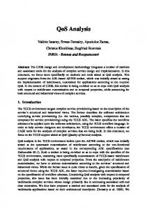
DMT modulation was chosen by ANSI for the standardization of ADSL [l]. Ideally, DMT modulation converts a channel with Inter Symbol Interference (ISI) into a set of N independent ISIfree subchannels by use of frequency division partitioning of the channel spectrum using the Discrete Fourier Transform (DFT) [lo], and each ISI-free subchannel can be modeled as shown in Figure 1, where Gain and Noise are the channel gain and noise power spectral density for subchannel i.
Subchannel h;;t ,-Q-TGain EELEQUIVALENT
Subchannel our Noise ISI-FREE
SUBCHANNEL
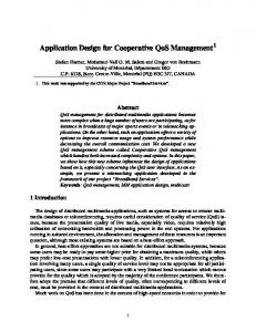
A lower speed QAM signal is then transported over each subchannel, or tone. A simplified block diagram of a basic DMT transceiver with FEC coding appears in Figure 2. After FEC encoding and interleaving for coded systems, the input bitstream is separated into blocks of b bits with each block forming one DMT symbol. Based on QAM analysis, these b bits are then distributed over the tones according to the subchannel Sirs measured during initialization and the target BER. The bi bits allocated to each subchannel are then mapped in QAM constellations of size 2bi, and the modulation is done digitally by use of the IDFT. The receiver merely consists of the inverse operations.
DMT system performance is then characterized by its noise margin at a given data rate and BER. user data FEC coding L & interleavmg
Bit distribution & Mapping
The geometric SNR approximation is a useful and simple way to estimate the margin: one can find from equation (2) the total number of bits per DMT symbol:
_
(3) where N OAM
Fig. 2: GENERAL STRUCTURE TRANSMISSION SYSTEM.
2.2
OF
A
The-geometric approximation in the -second part of (4+s valid when the SNRi are relatively high, which is the case for the tones chosen to carry bits. The geometric SNR is useful for computing the margin of a multichannel system given the data rate, the BER and the subchannel SNR as (derived from (3)):
DMT
Performance analysis (5)
This section reviews the performance analysis of Dh4T systems that will be used to compare the dual error rate DMT systems presented in the following sections. The performance analysis of DMT systems is derived from single channel performance analysis, the gap, which is a well-known measure of transmission system performance [4]. The gap, r, represents the system SNR distance from channel capacity: it is related to the number of bits per symbol, c’, and to the SNR (average received signal power to noise power ratio) by:
c’+og,
(
1+y
1
Equation (1) with r=l is the channel capacity formula that gives the best achievable number of bits per symbol [l 11. As I is becoming higher than one, the system’s performance moves away from the channel capacity. The value of the gap is determined by the BER and the line coding scheme [4]. For practical systems, a security margin, ym, is generally wanted to account for unknown channel distortions. ym, is defined as the amount by which the SNR can be lowered before the BER degrades to less than the target BER used in defining the gap [4]. When we include the margin, Tis replaced by rym in equation (1). As DMT is a multichannel modulation, the number of bits that can be supported on each subchannel at a specified BER with a given noise margin is:
3.
DUAL BER FOR UNCODED DMT SYSTEMS
In a basic DMT system, all applications are multiplexed together and transmitted at the same BER. Now, based on the observation that applications may require different BER for transmission [ 121, we examine an uncoded DMT system that provides simultaneously two different BERs. Applications are multiplexed in two streams, a data1stream and a data2stream, based on their QoS requirement, and each stream is transmitted with a different BER, BERl for data] and BER2 for data2. In uncoded DMT systems each ZD-QAM subsymbol error rate,
P,,
i, is entirely determined by the choice of the bits and power
allocation to the tones which is done during initialization from the knowledge of the subchannels SNRs. QAM analysis ]8] shows that under optimum detection,
PzD,, is
bounded as:
W, for any biZ1, where Q is the complementary function. We will use the upper bound of
N
~9
where SNRi, fi and ymi are respectively, for each subchannel i, the SNR, the gap and the noise margin. Now, if we ensure equal BER on the tones, Ti are equal for all the tones as are ymi. The
tightly upper-
P2,,,
Gaussian error for simplicity.
Regarding power allocation, it was shown in [4] that a flat transmit spectrum performs very close to the optimal waterpouring solution of information theory for DMT systems, and we consider only a flat transmit spectrum in the following. In order to design the dual BER uncoded DMT system, we propose to separate the tones into those that carry dutul with a BER equal to BERl and those that carry data2 with a BER of
BER2. Now, in order to decide weather the tones will carry data], data2 or will not be used at all, and in the case of a used
tone, to decide how many bits it will carry, we defined an algorithm, called the “dual bit loading algorithm.” It is inspired by the infinite granularity (i.e. bi is not forced to be an integer) noise margin optimization bit loading algorithm defined in [4] and referred as the basic mono bit loading algorithm in the following. The inputs of the dual bit loading algorithm are the data1 and data2 bit-rates and BER (rl, ‘2, BERl and. BER2 respectively) as well as the subchannels SNRs. The algorithm works on the following criteria: based on the performance analysis of section 2.2, compute the data] and data2 noise margins for each new tone in the cases that this tone will carry data] or data2, that is compute: -.7._ l
yml,l: data1 noise margin in the case that the current tone carry datal,
l
ym2,f: data2 noise margin in the case that the current tone cany data],
l
yml,2: data1 noise margin in the case that the current tone cany data2,
l
ym2,2: data2 noise margin in the case that the current tone cany data2,
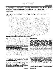
Now, the decision is: the current tone will be turned on if y,,rl,x or ~~2,~ is higher with this tone than without it, with x standing for I or 2. In the case the current tone is chosen to be used, it will cany the data that leads to the closest dotal and data2 noise margins. Indeed, unequal data1 and data2 noise margins means that data1 and data2 do not have BERl and BER2 as their error rates. Now that we have defined the dual bit-loading algorithm, let us evaluate its performances in comparison with the existing basic mono bit-loading algorithm. In order to have a fair comparison we obviously took equal BER for ahal and data2. The transmission characteristics are: the channel is the first reference model of the Carrier Serving Area (CSA) test loops [3]. It begins with a 5900’126 (line of length 900 feet’s and gauge 26), then includes a 600’/26 bridged tap and terminates with a 1800’R6 line. The noise includes -140 dBmiHz of Additive White Gaussian Noise (AWGN) and 10.1% worst case disturber Far End XTalk (FEXT) whose model is given in [I]. The input power is 110.4 mW. &al and &a2 rates are both qual to half the overall data-rate which is l500 bits per DMT symbol, but similar results where found with different values. The achievable noise margin with both loading algorithms under the above transmission characteristics (we refer to them as “channel CSAI”) is plotted on Figure 3 for different error rate values. What we see is that the difference in achievable noise margin is very low (less than 0.1 dB), and thus that the “dual” bit-loading algorithm does not introduce deficiency in comparison with the basic mono bit-loading algorithm.
1
C
Fig. 3: “DUAL” AND “MONO” BIT-LOADING ALGORITHM PERFORMANCE COMPARISON. We have shown that it is possible to design an uncoded DMT system with dual error protection by affecting different error rates on the tones. The interest of such a system in comparison with a basic DMT system comes from the observation that the achievable noise margin can vary a lot with the required BER for transmission: as an illustrative example, the achievable noise margin on channel CSAl is 10.3 dB at a BER of 10-3, 6.4 dB at IO-7 and 4.8 dB at 10-10. If the are transmitted with the same BER, this BER has to be the recommended BER of the most critical application, and a loss of noise margin, or throughput, will occur because some of the applications will be more protected than they need. For example, this loss of margin is equal to 1.75 dB between a system where all data is at lo-7 vs. one with half the data at IO-3 on channel CSAl.
4.
DUAL BER FOR CODED DMT SYSTEMS
Practical transmission systems often use FEC to improve their performance. At the cost of adding some redundancy to the transmitted data, FEC leads to a lower BER. Byte oriented (i4.K) Reed-Solomon (RS) codes are used for ADSL and VDSL and can correct up to (N-K)/2 bytes in error per codeword. Assuming that the RS code will make no correction if more than (N-K)/2 bytes are in error and that errors appear random at the decoder’s input, [8] relates the byte error rates before (P&) and after (Q,,& correction by:
r is the number of combination of i elements among N 0 elements. The performance of an FEC code used in conjunction with DMT modulation is measured in terms of the noise margin difference between a coded and an uncoded system that both perform at the same data rate and BER This noise margin difference is called the coding gain of the FEC code. Coded systems noise margin is calculated in the same way as for where
uncoded systems except that the target error rate for transmission is replaced by the error rate before RS decoding and the informative data rate is replaced by the coded data rate that includes the code’s redundancy. This section addresses the problem of the design of a dual error rate coded DMT transmission system. Two possibilities are envisaged: the first one (system A) provides dual error protection thanks to FEC only, i.e. data! and data2 are separately FEC encoded by two different Reed Solomon codes (Nt,Kt) and (N2.K2) and then modulated and transmitted without any distinction between them. The second possibility (system B) provides dual error protection not only by use of two different Reed-Solomon codes for data1 and data2, but also by use of the DMT modulation as in%%tion 3. The objective is to compare systems A and B performances. The method is to exhaustively look for the codes of best coding gain at targeted t-1, r2, BERl and BER2 for systems A and B and then to compute the noise margin of both systems as explained two paragraphs above. Note that optimum codes for both systems differ because for system A we have the constraint that the data] and data2 error rates before RS decoding have to be equal (because no distinction between data] and data2 is done at the modulation level).
System A codim
error rates to the tones to design a coded dual error rate transmission system.
5.
DMT
SUMMARY
In this paper, we presented and analyzed several possibilities for the design of coded and uncoded DMT systems that provide simultaneously two different error rates for transmission. We first proposed to provide dual error rate at the modulation level for uncoded systems, and then give a method to choose how bits and data can be allocated to the tones. For coded DMT systems, we found that such a differentiation at the modulation level is not worth and that dual error protection can be realized only by adequate FEC. -
6.
REFERENCES
[1] ANSI Tl.El.4\97-007R4 ADSL standard, 1997. [2] Barton M., “Unequal Error Protection for Wireless ATM Applications “, Globecom’96, Westminster, London, 1996. [3] CiofIi J.M ‘Asymmetric Digital Subscriber Lines”, draf? chapter from the CRC Handbook of Communications. [4] Chow P.S.. “Bandwidth Optimized Digital Transmission Techniques for Spectrally
Shaped Channels with Impulse
Noise”, Ph.D. dissertation, Stanford University, 1993. [5] Chow J.S. ‘Finite Length Equalization fir Multicarrier Systems”, Ph.D. dissertation, Stanford University, 1992. [6] Modlin C.S., Tong P., Chow J.S., “A comparison of proposed FEC and interleaving schemes for DMT and CAP”, ANSI TlE1.4 contribution n096-337, November 11,
1996. [7] Morelos-Zaragoza,
“Multilevel Block Coded Modulation with Unequal Error Protection”, ISIT’97, Ulm, Germany,
(255,23S] (255,239:
2.80
IO.82
Table. 1: SYSTEMS A AND B COMPARISON FOR DIFFERENT PERCENTAGES OF DATAI AND DATA2 RATES.
June 29-July 4, 1997. [8] Proakis J.G. “Digital Communications”, MC Graw-Hill, third edition, 1995. [9] Ptycker M., “ATM, solution for Broadband ISDN”, Englewood Cliffs, 1993. [lo] Ruiz A., Cioffr J.M.. Kasturia S., “Discrete Multiple Tone Modulation with Coset Coding for the Spectrally Shaped Channel”, IEEE Trans. Comm., vol. 40, n”6, June 1992 Mathematical Theoty of [1 l] Shannon ‘A C.E. Communication “, the Bell Systems Technical Journal,
1948. [12] Young G. “ATM over ADSL”, ANSI TlEl.4
no96165, July 22, 1996. Table 1 shows the comparison on channel CSAI with different proportions of data1 and data2, 1500 bits per DMT symbol and 2D-QAM subsymbol error rates quaI to 104 for data] and 10-7 for data2. We assumed in the calculations that one subsymbol in error leads to 1.3 bytes in error [6] and vice-versa. It appears that system B performs better than system A by only a few tenth of dB, and that this performance difference essentially comes from a difference between the systems A and B RS codes performances. We ran simulation over other channels that lead to similar results. As system B is more complex than system A and as the difference in achievable noise margin between both systems is insignificant, we conclude that it is not worth to affect different
contribution