RAPID CONTROL PROTOTYPING APPROACH TO FUZZY SPEED CONTROL OF BRUSHLESS DC MOTOR R. Nejat TUNCAY
Zeynep ERENAY
Murat YILMAZ
Özgür USTUN
e-mail:
[email protected] [email protected] [email protected] [email protected] Istanbul Technical University, Faculty of Electrical & Electronics Engineering, Department of Electrical Engineering, 34469, Maslak, Istanbul, Turkey Key words: Fuzzy control, DSP, brushless dc motor, membership function. ABSTRACT This study involves the fuzzy logic controlling of brushless DC (BLDC) motor with rapid control prototyping method. Initially a MATLAB/Simulink model of the six pulse BLDC motor and its power electronic driver is established. A fuzzy controller is developed by using MATLAB Fuzzy-Logic Toolbox and then it is inserted into the Simulink model. This model is directly communicated with a DSP through DS2201 dSPACE digital signal kit. PWM pulses are produced on the simulation model and DSP C program is directly developed through dSPACE system. It is shown that, fuzzy controller is successfully controlling the motor and, the model based programming of DSPs is very simple and versatile comparing with that of conventional method. I. INTRODUCTION In modern intelligent motion applications the demand to the accurate speed and position control is increasing. In the mean time, it is also expected that control systems should be reliable, cost effective, robust and, having with low volume, weight and maintenance requirement. In this respect, a tailor type specific design of control systems offers advantageous over conventional control systems. This study aims to develop a methodology in designing a versatile control system, which is capable to meet the adverse requirements of each application in minimum time with minimum changes and maximum reliability. It is known that an electromechanical motion control system has the following components: an electric motor, power electronics supply, control hardware and software. Permanent magnet motors have higher specific torque values (torque/weight) and widely preferred in high quality drive applications [1, 2, and 3]. On the other hand, these motors require a power electronics driver and rotor position sensors or methods to define the rotor position. In order to achieve the required motion, power electronic switches should be triggered and PWM supply voltage be applied to the armature winding of the motor. All of these functions are achieved by control hardware, namely
a microprocessor or a DSP. With parallel to the increase of more challenging applications in industry, in spite of their higher cost, DSPs are becoming more popular. Software programming of a DSP is still a tedious task and requires time. Recent improvements on producing c programming of DSPs through MATLAB based software/hardware communication yields fruitful results. As it is known that this method is called rapid control prototyping. Since all of the drive system is modeled in MATLAB environment it is easy and fast to make changes in control parameters to produce the best response for the varying loads [4, 5]. Generally PI controller is widely used in BLDC motor control; however it does not give satisfactory results when control parameters and loading condition changes rapidly [6]. The fuzzy speed controller (FLC) will guarantee a stable operation, even if there is a change in motor parameters and load disturbances. The reason is obvious, any control system maps the input space to the output space. Generally, a desired set of outputs are calculated for a given set of inputs. This mathematical calculation is represented with a formula, which demonstrates the system behavior. However, this mathematical formula may be too complex and meaningless to use for the real world issues. In these cases, fuzzy logic provides a useful methodology to create a practical solution for controlling complex systems. It is not necessary to know the exact model of such complex systems in order to design a FLC. It is sufficient to understand the general behavior of the system. Fuzzy logic enables the designer to express the general behavior of the systems in an easier (linguistic) manner where it is allowed to use words and sentences instead of numbers and equations. This is accomplished by forming IF-THEN rules which describe the characteristics of the system [7]. Fuzzy logic is applied in various areas. Washing machines, subway systems, video cameras, sewing machines, rice cookers, biomedical and finance are among these application areas of fuzzy logic. There have been
various fuzzy logic controller applications in brushless dc motor control [8].
dω r 1 = {Te − Bω r − TL } dt J
Initially a MATLAB/Simulink model of the six-pulse BLDC motor and its power electronic driver is established. A fuzzy controller is developed by using MATLAB Fuzzy-Logic Toolbox and then it is inserted into the Simulink model. The speed control of the BLDC motor is secured by a cascade controller, which consists of two fuzzy controllers. These fuzzy controllers emulate some kind of human expert who knows how to change the applied dc voltage for various values of the error and the change of error in speed and line currents of the motor. This fuzzy controller model in MATLAB/Simulink is directly communicated with a DSP through DS2201 dSPACE hardware- software kit. Since Hall Effect signals are also transferred to the model, the produced PWM signals comply with the position of the permanent magnets as well as the performance objectives.
dθ r = ω r , θ e = pθ r dt
II. MATHEMATICAL MODEL OF BLDC MOTOR The mathematical model of BLDC motor drive system, which is shown in Figure 1, consists of a diode rectifier, an IGBT inverter, three phase winding resistances, inductances and back EMFs. The six pulse operation of the state-space model of the system, including commutation intervals, are developed [9]. The simuling model of the system is established by using these state equations. The simulation results for a constant load are presented in Figures 2, 3, 4, 5, and 6.
V = R ⋅i + L
Figure 2.Phase currents versus time of BLDC motor
di +e dt
Figure 3.Emf versus time of BLDC motor
Figure 1.Equivalent circuit of BLDC motor
R 1 − 0 0 − 0 0 L L V e (t) i (t) i1(t) 1 1 1 d R 1 0 i2(t) + 0 − i2(t) = 0 − 0 ⋅V2 −e2(t) dt L L i3(t) R i3(t) 1 V3 e3(t) 0 0 − 0 0 − L L 1 (e1 (θ e )i1 + e2 (θ e )i2 + e3 (θ e )i3 ) Me =
ωr
e = 2 NlrBw
1 dL 1 2 dR 4 N Me = i2 Brlπi − B + dθ π 2 dθ 2
Figure 4.Speed versus time of BLDC motor
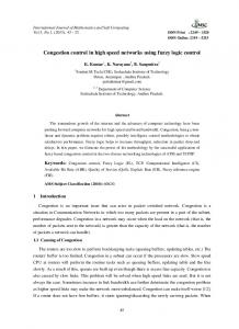
Figure 7.Mem.ship functions related with speed error (e)
Figure 5.Simulink block diagram of BLDC motor III. DESIGN OF FUZZY LOGIC CONTROLLER The purpose of the speed control of a brushless dc motor is to arrange the applied voltage in order to reach a reference speed. An error is determined by the difference of the actual speed and the reference. The applied voltage should be changed by increasing or decreasing the duty cycle of power transistors in order to minimize the error.
Figure 8.Membership function related with the change in the speed error (ce)
Figure 9.Membership functions of calculated and applied voltage changes (cvi, kcv)
Figure 6.Torque versus time of BLDC motor The fuzzy speed controller of the BLDC contains two separate blocks of rules [10, 11]. The three phases of fuzzy logic process, which are fuzzification, inference and defuzzification, are implemented by using MATLAB Fuzzy Logic Toolbox. The inputs of the first block are the speed error (e) and the change in the speed error (ce). The output of the first block is the calculated voltage change (cvi) which is also the input of the second block. Another input to the second block is the highest line current (i) of the motor at that moment. The output of the second block is the applied voltage change (kcv). The membership functions related with speed error (e), the change in the speed error (ce), the calculated voltage change (cvi), the current (i) and the applied voltage change (kcv) is demonstrated in Figures 8, 9, and 10.
Figure 10.Membership functions of the current (i) The Simulink model of the whole system is shown in Figure 11. The fuzzy block A calculates the voltage error according to the speed and change of speed errors [12]. This voltage change would be high if high speed error and low change of speed is the case. However, the question is whether this voltage change should be applied or not. If the current is in the area of rated current, a high voltage change would make the motor draw an over rated current, which would damage the motor windings in the long run. The second block, which is called block B in Figure 10,
determines whether the calculated voltage change should be applied or not (or how the calculated voltage should be applied). If the current is over its rated value, the voltage change may be zero or in the reverse direction. Fuzzy controller speed and current rule bases are shown in Table 1 and 2. Table 1.Fuzzy controller speed rule base (Block A) ce
NB
NS
ZE
PS
PB
NB
NB
NB
NB
NS
NS
NS
NB
NB
NS
NS
NS
Z
NB
NS
Z
PS
PB
PS
PS
PS
PS
PB
PB
PB
PS
PS
PB
PB
PB
e
Table 2.Fuzzy controller current rule base (Block B) cvi
NB
NS
ZE
PS
PB
UR
NB
NS
ZE
PS
PB
R
NB
NS
ZE
ZE
ZE
OR
NB
NB
NS
NS
NS
i
IV. SIMULATION RESULTS In this section, the overall model of BLDC motor with fuzzy logic controller is implemented in MATLAB/Simulink. Block diagram of fuzzy logic control in Simulink model is given in Figure 11.
The computer simulation runs such that the speed of the BLDC motor remains at 52 rpm (reference speed) in the steady state, even if the load is changed. This constraint is provided by means of the fuzzy logic controller. Error is calculated by subtracting the reference speed and the speed at the moment. Taking the difference between the present error and the error of the previous sampling period, change of error is calculated. According to the error and the change of error, first block of the fuzzy logic controller calculates a voltage change (cvi). The second block of the FLC computes the voltage change that should be applied to the BLDC motor by taking the calculated voltage change and the current of the BLDC motor into account. This procedure is necessary to avoid the BLDC motor draw overrated currents.
Figure 11.Simulink block diagram of fuzzy logic control. This fuzzy model is directly communicated with digital signal processor through DS2201 dSPACE kit. The PWM pulses are produced on the simulation model and DSP C program is directly developed through dSPACE system. It is shown that, fuzzy controller is successfully controlling the motor and, the model based programming of DSPs is very simple and versatile comparing with that of conventional method. In Figure 13 the block representation of this system is shown. In order to test the effectiveness of developed fuzzy system the fuzzy speed control of the BLDC motor is simulated in Simulink in which the load is changed twice. After the speed set to 52 rpm at steady state, the load is increased first. It set again to 52 rpm at steady state. At that point, the load is decreased, and the motor can set to 52 rpm once again. Figure 12 demonstrates that BLDC motor is settling to 52 rpm successfully, when these load torque changes occur.
(a)
7.
(b) Figure 12 (a,b). Load Torque the settling of the BLDC motor to 52 rpm in case of these load torque changes. V. CONCLUSION This study involves the fuzzy logic controlling of brushless DC (BLDC) motor with rapid control prototyping method.
George Bojadziev, Maria Bojadziev, “Fuzzy Sets, Fuzzy Logic, Applications”, Vol. 5, September 2000. 8. Bolognani, S., and M. Zigliotto, “Inferential Processor Based Fuzzy Control for an Electric Drive”, 5th European Conference on Power Electronics and Applications, Exeter: Short Run Press Ltd., 1993. 9. L. Tezduyar, “Fırçasız Doğru Akım Motorlu Tahrik Sistemlerinde On İki Darbeli Sürücü”, Doktora Tezi, Haziran 1997. 10. Vas, Peter, “Artificial-Intelligence-Based Electrical Machines and Drives”, New York: Oxford University Press, 1999. 11. Bin Wu, “Brushless DC Motor Speed Control”, Dept. of Electrical & Computing Engineering, Ryerson University, October, 2001. 12. Zaki Aziza, “ANN-Based Current Controlled BLDC Servo-Motor”, 9th European Conference on Power Electronics and Applications, EPE 2001, Graz, 27-29 August 2001.
A Simulink model of brushless dc motor is established, a fuzzy controller which controls the voltage and current is inserted in this model, which is directly communicated with a DSP through DS2201 dSPACE digital signal kit. It is shown that, fuzzy controller is successfully controlling the motor and, the model based programming of DSPs is very simple and versatile comparing with that of known methods. The design of a such fuzzy logic controller enables to handle with parameter variations and load disturbances. This type of controller is more robust and fast that other conventional control techniques. 1. 2. 3. 4.
5.
6.
REFERENCES Bose, I., “Power Electronics and Variable Frequency Drives”, New York: IEEE Press, 1996. D.C. Hanselman, “Brushless Permanent Magnet Motor Design”, Mc. Graw Hill, 1994. Hendershot Jr., J.R., and Miller, TJE. “Design of Brushless Permanent-Magnet Motors”, New York: Oxford University Press, 1994. Tadeusz Uhl, Tomasz Bojko, Zbigniew Mrozek, Wojciech Szwabowsk, “Rapid Prototyping of Mechatronic Systems”, Published in Journal of Theoretical and Applied Mechanics, pp645-668, 2000. Texas Instruments, “Enhanced Control of an Alternating Current Motor Using Fuzzy Logic and a TMS320 Digital Signal Processor”, Digital Signal Processing Products, 1996. Erenay, Kerem, “Application of Fuzzy Algorithms to the Speed Control of Washing Mashines”, B.S. in E.E., Boğaziçi University, 1995.
Figure 13.Full fuzzy logic-DSP system concept.