Ray Tracing Animated Scenes using Motion Decomposition. Johannes Günther1, Heiko Friedrich2, Ingo Wald3, Hans-Peter Seidel1, and Philipp Slusallek2.
EUROGRAPHICS 2006 / E. Gröller and L. Szirmay-Kalos (Guest Editors)
Volume 25 (2006), Number 3
Ray Tracing Animated Scenes using Motion Decomposition Johannes Günther1 , Heiko Friedrich2 , Ingo Wald3 , Hans-Peter Seidel1 , and Philipp Slusallek2 1 MPI Informatik, Saarbrücken, Germany 2 Saarland University, Saarbrücken, Germany 3 University of Utah, Salt Lake City, USA
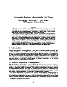
Figure 1: Example images from animations ray traced in realtime. From left to right: H AND, B EN, C HICKEN, C OW, and D OLPHIN. The color encodes separated clusters generated by our motion decomposition algorithm. All animations combine flexible non-affine body motion from skinning, and other deformations. They can be ray traced with 5 to 15 frames per second at 1024 2 on a single CPU.
Abstract Though ray tracing has recently become interactive, its high precomputation time for building spatial indices usually limits its applications to walkthroughs of static scenes. This is a major limitation, as most applications demand support for dynamically animated models. In this paper, we present a new approach to ray trace a special but important class of dynamic scenes, namely models whose connectivity does not change over time and for which the space of all possible poses is known in advance. We support these kinds of models by introducing two new concepts: primary motion decomposition, and fuzzy kd-trees. We analyze the space of poses and break the model down into submeshes with similar motion. For each of these submeshes and for every time step, we calculate a best affine transformation through a least square approach. Any residual motion is then captured in a single “fuzzy kd-tree” for the entire animation. Together, these techniques allow for ray tracing animations without rebuilding the spatial index structures for the submeshes, resulting in interactive frame rates of 5 to 15 fps even on a single CPU. Categories and Subject Descriptors (according to ACM CCS): I.3.7 [Computer Graphics]: Ray tracing I.3.6 [Methodology and Techniques]: Graphics data structures and data types
1. Introduction and Related Work With recent improvements in PC hardware and ray tracing technology, ray tracing has finally become interactive. Even realtime frame rates for full-screen images have recently been reported on a single CPU [RSH05] for nontrivial scenes with millions of triangles. Nevertheless, most techniques only support static walk-through applications. On the other hand, many rendering applications require dynamically changing scenes which is not yet well supported in realtime ray tracing approaches. In this paper we focus on an important subset of dynamic scenes, particularly where all poses of a dynamic object are known in advance and the mesh connectivity is constant across the animation. Right know, realtime rendering of animations is essen© The Eurographics Association and Blackwell Publishing 2006. Published by Blackwell Publishing, 9600 Garsington Road, Oxford OX4 2DQ, UK and 350 Main Street, Malden, MA 02148, USA.
tially the domain of rasterization hardware due to its support for immediate mode rendering and its strong hardwareacceleration, e. g. for vertex shaders. Ray tracing, first discovered by Appel et al. [App68], on the other hand is well known for its high rendering quality but was in the past considered as too slow for realtime 3D applications. However, in recent years numerous publications reported interactive or even realtime rendering frame rates [Muu95, PMS∗ 99, WSBW01, RSH05]. However, in order to achieve good ray tracing performance it is necessary to make use of spatial index structures that yield sublinear rendering complexity in the number of primitives. Many different data structures for accelerating ray tracing have been proposed including, among others, octrees [Gla84, Arv88], bounding volume hierarchies [RW80],
Günther et al. / RT using Motion Decomposition
grids [CWBV83, AW87], ray classification [AK87], binary space partitioning [FKN80], and kd-trees [Jan86, SF90]. In particular kd-trees built with heuristics to minimize the expected traversal cost – such as the surface area heuristic (SAH) [MB89] – have shown to work very well. Even though some variations in scenes remain, extensive statistical comparisons have shown that in general kd-trees perform best or are at least highly competitive with the best one [HPP00]. As a result, most realtime ray tracing systems today use kd-trees including CPU-based systems [Wal04, RSH05], ray tracing hardware [WSS05], and GPU-based ray tracers [FS05]. Apart from optimized acceleration structures and hardware improvements, recent rendering speed improvements are also achieved due to the usage of SIMD extensions like SSE or Altivec to parallelize traversal, intersection, and shading operations [WSBW01]. Recently Multilevel Ray Tracing (MLRT) with inverse frustum culling traversal and kd-tree entry-point search [RSH05] allows to further improve the performance by almost one order of magnitude. Dynamic Scenes In general, various different types of motion can be observed. In this paper we will distinguish between four kinds of dynamics in 3D mesh-based computer graphics. First, there are static objects that are not deformed nor is their position in space altered. In ray tracing, static objects can be rendered very quickly using kd-trees [RSH05, WSBW01, Hav01]. Second, there are objects which undergo simple affine transformations like translation or rotation. Lext et al. [LAM01] proposed a hierarchy of oriented bounding boxes to minimize reconstruction times via lazy rebuilds for this kind of dynamics. Furthermore, Wald et al. [WBS03] have proposed a two-level kd-tree scheme based on hierarchically affine transforming submeshes. Though this is sufficient for several engineering-style VR applications, more general animations cannot be handled. Thirdly, there is completely random motion like in particle systems and turbulence simulations. The rendering of random motion, as described, can be achieved using interactive grids by Reinhard et al.’s [RSH00] using an SGI Onyx 2000 with 32 processors. Finally our last category is (piecewise) continuous dynamics (PCD). This last type of motion is in our real world abound and in graphical systems like games and animated movies widely simulated. PCD for example can be observed if wind bends a tree and the leaves are waving or if fingers are moved and its skin is stretched or squeezed. While kd-trees are well suited for static scenes, considerable effort is required for building them well. Though efficient algorithms with O(N log N) complexity exist [WH06] they often require seconds to minutes even for moderately complex scenes. This pre-processing time is almost negligible for walk-through applications with a static geometry
environment, but it is not acceptable to update or rebuild the kd-trees at runtime due to changes in the scene. Eventually, this leaves but three choices: Speed up kd-tree building to make it suitable for interactive applications, abandon kdtrees for dynamic scenes and try to develop competing data structures to yield similar performance, or extend kd-trees such as to allow for certain kinds of motion. It is important to note that any support for dynamic scenes is inherently based on assumptions or specific knowledge about the types of dynamics contained in a scenes. If no information were available, e.g. in completely random motion, we would have to rebuilt the spatial index for every frame as any geometry may have seen random transformations in any frame. In this paper, we will investigate the usage of kd-trees for (piecewise) continuous dynamic objects. For the course of this paper, we will assume that objects are defined as deformations of a base mesh i.e. the connectivity of the mesh remains the same for every pose of the mesh, e.g. the animation is given by a set of different poses. Second, we assume that the set of possible deformations of that mesh is bounded and known in advance. A good example is a game character defined through skinning of a base skeleton, for which the set of valid poses is defined through the valid parameterizations of the underlying skeleton, but we do not need this bone information. 2. Method Overview For these kinds of dynamic scenes, our new method still allows for utilizing the performance and advantages of kdtrees by compensating the deformations of the model. We use a motion decomposition approach for this purpose. It breaks the deformations into two parts: an affine transformation, and the residual motion. Subtracting the affine transformation from the animation yields a local coordinate system in which the (residual) motion of the vertices is typically much smaller (see also Figure 2). The residual motion of each triangle is then bounded by a fuzzy box, a box bounding the motion of each vertex in the local coordinate system. The kd-tree is then build over the fuzzy boxes of the triangles instead of the triangles themself, resulting in a fuzzy kd-tree. This needs to be done only once in a preprocessing phase as the fuzzy kd-trees are valid for the entire animation sequence (see Figure 3). As the efficiency of a fuzzy kd-trees obviously deteriorates quickly with increasing size of the fuzzy boxes we do not build a single fuzzy kd-tree for the entire scene. Instead, we cluster the mesh into sub-meshes of coherent motion by using the amount of residual motion as a cost function that must be minimized. A huge number of mesh segmentation algorithms have been proposed in the past. However, most of these meth© The Eurographics Association and Blackwell Publishing 2006.
Günther et al. / RT using Motion Decomposition
����������������������� ����������� �� ��������������������� ��� ��� ��� ��� ��� ��� ��� ��� ��� ��� ��� ���� ��� ��� ��� ��� ��� ��� ��� ��� ��� ��� ��� �� ���������������������� �� ����������������������� ��� ��� ��� ��� ��� ��� ��� ��� ��� ��� ��� �� ������������
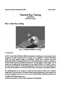
Figure 2: Example of a motion decomposition. Top row: Three frames of an example animation where a ball is thrown onto a floor. The bounding boxes and local coordinate systems of the two separated objects are shown. The motion of these objects is encoded by affine transformations extracted from the animation. Bottom row: Visualization of the bounded residual motion in the local coordinate system of the ball. Note that the affine transformations can also compensate the shearing of the ball in the third frame yielding smaller fuzzy boxes.
Figure 3: The residual motion of each triangle (green) is bounded by a fuzzy box (red). Although the triangles move a little bit in the local coordinate system their fuzzy boxes do not change. As the fuzzy kd-tree is build over these fuzzy boxes instead of the triangles it is valid for all time steps.
ods work only on statics meshes. Nevertheless, for animation data Sattler et al. [SSK05] used a variant of Principal Component Analysis (PCA) to segment the mesh into parts that are “coherent” over time prior to compression. Although promising it showed that their algorithm produced unusable clusters for our purpose as it was designed with mesh compression in mind and not for ray tracing. Recently Lee et. al [LLYL05] proposed a mesh decomposition method using information from animation sequences. After applying PCA only once for the mesh they analyze the resulting PCA-weights to derive a motion similarity measure of vertices. This measure is then used to guide a region growing algorithm to cluster the mesh. As an intermediate step to skin mesh animations James and Twigg [JT05] used mean shift clustering of rotation sequences of triangles to segment an animated mesh into near-rigid structures. However, the vertices are expressed as weights of several transformations and thus this method can not be used for ray tracing animations. © The Eurographics Association and Blackwell Publishing 2006.
Therefore we decided to develop our own clustering algorithm specifically designed for the purpose of ray tracing animated meshes. The motion of the mesh is analyzed to segment the mesh into clusters of similar motion and we find affine transformations for each cluster to express this common motion (Section 3.1). Because in our approach the relationship between the clusters and their motion is determined by affine-only transformations we can use a two-level scheme similar to [WBS03]. For each frame to be rendered we update the transformations of our clusters and rebuild a small top-level kd-tree over the current bounding boxes of the clusters (Figure 4).
Figure 4: To ray trace a frame of an animation we first build a small kd-tree over the current bounding boxes of each cluster. These boxes are shown for three frames of the CHICKEN animation. Rays hitting a cluster get inversely transformed into the local coordinate system of this cluster and traverse its fuzzy kd-tree. Then ray traversal starts in the top-level kd-tree. For every intersected clusters the rays are transformed into the local coordinate system of the hit cluster where they traverse the associated fuzzy kd-tree. When the ray traverses a leaf it must be tested against the current instantiation of any contained triangle. This triangle intersection test can be done in world coordinate system with the untransformed rays. Thus the positions of the triangles in the local coordinate system are not explicitly required for rendering thus saving memory. Our approach is summarized in Figure 5. 3. Motion Decomposition and Fuzzy KD-Trees This section discusses the details of the motion decomposition approach and fuzzy kd-trees and provides a more formal description of the techniques involved. Our method requires that the animation is defined as deformations of a base mesh, i.e. that the connectivity of the mesh remains the same for every time step. Thus the animation is given by a constant set of triangles {∆} and their vertex positions {v}. vi (t) ∈ R3 describes the motion of a vertex over time. No additional knowledge about the deforming mesh is necessary but we inherently assume coherent lo-
Günther et al. / RT using Motion Decomposition
(a)
(b)
(c)
(d)
(e)
Figure 5: Motion decomposition together with fuzzy kd-trees allow for ray tracing animated models with continuous deformation by decomposing the motion of the mesh into an affine transformation plus some residual motion. (a) One frame of the H AND animation, modelled with “Poser”. (b) The deforming mesh is split into submeshes of similar motion, shown in the rest pose. (c) Reconstruction of frame (a) using the affine transformations of each cluster only. (d) Close-up view of (c) revealing the erroneous mesh when approximated only by an affine transformation. (e) Adding the residual motion handled by the fuzzy kd-trees yields the original mesh.
cal motion, i.e., vertices that are topologically close to each other should have similar trajectories.
local coherence in motion, which requires a clustering of the mesh into submeshes that deform coherently.
We exploit this coherent motion of the mesh to “subtract” common motion because the resulting smaller residual motion can then be better handled by fuzzy kd-trees, thus improving performance for ray tracing the animation. Mathematically this motion decomposition can be described as follows. The position v at time t of the vertices in world space can then be expressed by applying the appropriate affine transformation X to a rest pose M˜ = {v} ˜ plus a residual motion δ:
To partition the triangles of the mesh into clusters we apply a generalized Lloyd Relaxation [Llo82] algorithm (see e.g. [DFG99] for an introduction). Note that we need to cluster triangles and not vertices because the triangles will be tested for intersections with rays.
vi (t) = X(t) · v˜i + δi (t)
(1)
The rest pose of an animated object is a mesh where usually all parts of the object are in a relaxed position. Transforming into the coordinate system of the rest pose by multiplying (1) with the inverse Transformation X −1 (t) and substituting δ˜ i (t) = X −1 (t) · δi (t) yields v˜i (t) = v˜i + δ˜ i (t) = X −1 (t) · vi (t),
(2)
the fuzzy position v˜i (t) of vertex i at time t. The fuzzy box FB(∆abc ) of triangle ∆abc with vertices a, b, c is the axis-aligned bounding box (AABB) of all fuzzy positions v˜a (t), v˜b (t), v˜c (t)∀t and bounds the local residual motion ˜ δ(t). The fuzzy kd-tree is then build over these fuzzy boxes instead of the triangles and is thus valid for all time steps. 3.1. Clustering of Coherent Motion Obviously the performance of the fuzzy kd-tree for ray tracing is strongly dependent on the size of the fuzzy boxes. If all fuzzy boxes are quite big and overlap themselves significantly the acceleration structure can hardly discard triangles for intersection, resulting in many costly ray-triangle intersections. Therefore we like to keep the residual motion relatively small, or equivalently we want to subtract as much common motion as possible. This can only achieved by exploiting the
In each iteration step we first find affine transformations that minimize the residual motion of each clusters and second reassign each triangle to the cluster where its residual motion is smallest. The iteration process stops when the clustering converged, i.e. when no triangle change its cluster anymore. Practically we stop when the decrease in the overall residual motion drops below some threshold, e.g. below 1‰. As Lloyd relaxation is prone to find local minima and the optimal number of clusters is not known in advance we start with one cluster and iteratively insert a new cluster until the cost function converges. A new cluster is inserted in the following way. We take as seed triangle the triangle with the largest residual motion. We also also include its neighboring triangles such that they define a coordinate system. The existing clusters are also newly initialized with the seed triangles that have the smallest residual motion. These seed triangles act as prototypes of the common motion of the (currently) clustered triangles and ensure a stable clustering procedure. We stop adding clusters when the the overall residual motion cannot be reduced significantly anymore. See next Section for our cost function. The clustering process is shown in Figure 6. Note that the most similar moving parts of the mesh are clustered first. One can find the proposed clustering algorithm in pseudo code summarized in Algorithm 1. 3.2. Finding “Good” Transformations For the motion decomposition and the clustering we need to find affine transformations between the rest pose and all © The Eurographics Association and Blackwell Publishing 2006.
Günther et al. / RT using Motion Decomposition
Figure 6: Top row: Several frames of the H AND animation. Bottom row: Clustering of the H AND animation with 1, 2, 4, 8, and 12 clusters, respectively. Triangles with the same color belong to the same cluster. The out lined boxes denote the bounding box of each cluster. Note how the cost-driven clustering approach automatically segments the hand into clusters in which the triangles perform roughly the same motion. For example the pinky and the ring finger are clustered first as they perform similar motion.
Algorithm 1 Clustering start with one cluster containing all triangles of the scene while global cost still changes significantly do while cost not converged for current #clusters do find transformations, minimizing δ˜ ∀cluster recluster triangles, minimizing δ˜ end while create new cluster choose seed ∆s end while
other poses that minimize the residual motion kδ˜ i (t)k = kXt−1 · vi (t) − v˜i k ∀t. The affine-only 3 × 3 transformation matrix and its translation can be combined to a 4 × 4 transformation matrix using the homogeneous coordinate system. Thus X −1 has 12 unknown elements and we need (at least) 4 linear independent vertex positions for a unique solution. With more than 4 vertex positions (the general case) we solve the linear least squares problem that minimizes the L2 -norm ˜ kX −1 · vi (t) − v˜i k2 of the residual motion δ. Instead of minimizing the L2 -norm of the residual motion we really want to optimize the surface area of the resulting fuzzy boxes. This is more closely linked to L∞ -norm, but we found that this approach is already giving the right results while guarantying convergence. 3.3. Selecting the Rest Pose So far we have not yet defined the rest pose M˜ = {v}. ˜ To avoid an expensive general optimization problem we simply © The Eurographics Association and Blackwell Publishing 2006.
take the positions {v˜i (t)} of one of the key frames of the ˜ During the clustering we try all key frames animation as M. and take the one that minimizes the sum over all cluster c and all time steps t: t˜ = arg min kXc−1 (t) · vi (t) − vi (t 0 )k 0 ∑∑ ∑ t
t
c i∈c
(3)
If the animation consists of a large number of frames we uniformly subsample the set of frames while searching for an optimal rest pose in order to reduce the search space. 3.4. Optimizing Local Bounding Boxes We can make two observations that can lead to better ray tracing performance if exploited properly. First, when rays hit the axis-aligned bounding boxes of the clusters in the top-level kd-tree they get inversely transformed to the local coordinate system of that cluster. The following traversal of its fuzzy kd-tree starts by clipping the transformed rays to the local axis-aligned bounding box of the cluster. This is meaningful because the affine transformation can rotate the coordinate systems and thus rays hitting the globally axis-aligned box do necessarily also hit the locally axis-aligned box. Second, the vertices of each cluster can be rotated arbitrary in the local coordinate system because this rotation can be compensated by multiplying the affine transformations of the corresponding cluster with a rotation matrix. We can take advantage of these facts to make tighter local axis-aligned bounding boxes of clusters. By calculating an oriented bounding box (OBB) of the fuzzy positions and
Günther et al. / RT using Motion Decomposition
rotating this box to make it axis-aligned we can directly minimize the local bounding boxes. To approximately compute the OBB of each cluster (in local coordinates) we apply PCA to the fuzzy positions and take the first three PCA vectors as new coordinate system axes. Exactly finding the OBB [BHP01] could be used as well. 4. Implementation and Results We implemented our motion decomposition approach and the ray tracer with fuzzy kd-trees using C++, SSE [Int02], and the LAPACK [ABB∗ 99] library for fast matrix operations and linear algebra computations. The ray tracer implementation is equivalent to the approach in OpenRT [Wal04] with some extensions of MLRT [RSH05], namely the inverse frustum culling for kd-tree traversal. No further optimizations such as empty occluders or an efficient entrypoint search are included. The measurements were done on a workstation equipped with two AMD Opteron 2.8 GHz processors and a GeForce 6800 GT PCIe graphics board. Figure 1 shows several of our example scenes. They cover different amounts of animation complexity and contain between approximately 10k and 80k triangles. The H AND and B EN scenes are examples of hierarchical animations and were created with Poser [Pos] using a a skeleton with vertex skinning. Because this directly matches our assumptions we expect that our motion decomposition approach will perform well. Although the motion of the D OLPHIN is not controlled by a skeleton but by a massspring simulation it still moves naturally and thus also meets our assumptions. The C OW scene, on the contrary, shows highly unnatural motion. It is an example of an animation generated by a physics-based simulation of a cow consisting of very elastic material, resulting in “jelly-like”, unnatural poses. Finally, as a stress test for our algorithm, we choose the C HICKEN animation. This section of an animated film is difficult because of the extreme, cartoon-like sequences around frame 250 (see Figure 1c and the left of Figure 4) that include strong stretching of the chickens’ neck and oozing of its eyes. Even though the motion in the last two scenes violates the assumptions our method still works surprisingly well as demonstrated in the following sections. 4.1. Clustering Our proposed clustering algorithm minimizes the residual motion by using the least square distances of the vertex positions in the local coordinate system as a cost measure. However, the surface area of the fuzzy boxes is the better measure for the expected ray tracing performance [MB89]. Figure 7 compares these two measures during clustering. It shows that the least square distances by the relaxation-based
clustering is highly correlated with the surface area of the fuzzy boxes and both are minimized. Furthermore it can be seen that adding new clusters is not beneficial anymore at some point and clustering is automatically terminated by a threshold on the change of the least square distances. Also note that a number of clusters around 20–25 is sufficient for our example animations. The clustering process takes from about 20 minutes for the H AND to about 95 minutes for the C HICKEN when 25 poses were tested for the rest pose. The clustering time increases linear with the number of time steps and is also linear in the number of candidate rest poses. Thus it can be shortened drastically by subsampling the time steps during the clustering process with a negligable effect on clustering quality. Although our algorithm only sees the animated vertex positions of the mesh and has no knowledge about the underlying skeleton, the resulting clusters correspond well to the bones of the H AND and B EN model (see Figure 1a and 1b). Also for the D OLPHIN and even for the C OW and C HICKEN animations meaningful submeshes that move coherently were found (see Figure 1c, 1d and 1e).
4.2. Comparison to Static KD-Tree To evaluate the efficiency of our proposed fuzzy kd-tree for ray tracing animated scenes we compare it to a static kd-tree. Table 1 lists two characteristic values for acceleration structures, namely the number of traversal steps and the number of ray-triangle intersections. We compare our twolevel fuzzy kd-tree with an one-level kd-tree that is re-built and optimized for every time step. Apart from the structure of the resulting tree the traversal and intersection routines are the same for both kd-trees. The measurements show that the number of traversal steps increases by only 50% to 100% for the fuzzy kdtree. The ray-triangle intersections increase only by 15% for the H AND and typically up to 100%, except for the C OW and C HICKEN scene. Because these two animations do not strictly obey our assumption of local coherent motion the motion decomposition cannot work optimally resulting in a larger residual motion and overlap of the fuzzy boxes. This increased overlap affects the efficiency of the kd-tree and leads to an increased number of intersections. Although the increase in intersections of a factor of 6 for the C HICKEN may seem high, overall ray tracing performance is much less affected as shown in the following section and ray tracing this animation is still reasonably fast. Obviously the memory consumption of a separate static kd-tree per time step will linearly increase with the number of frames whereas the memory consumption of our fuzzy kd-tree will be roughly the same largely independent of the length of the animation. © The Eurographics Association and Blackwell Publishing 2006.
Günther et al. / RT using Motion Decomposition Residual Motion
Surface Area of Fuzzy Boxes
1e+09
10000
Ben Chicken Cow Dolphin Hand
1e+08 1e+07
Ben Chicken Cow Dolphin Hand
1000
surface area
residual motion
1e+06 100000 10000
100
1000 10
100 10 1
0
5
10
15
20
1
25
0
number of clusters
2
4
6
8
10
12
14
16
18
number of clusters
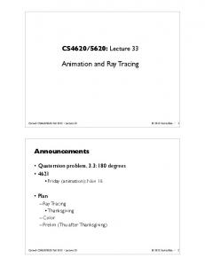
Figure 7: The sum of all residual motion and the accumulated surface area of the fuzzy boxes during the clustering process. The residual motion is minimized by our clustering algorithm while the surface area of the fuzzy boxes is proportional to the ray-intersection probability and thus a reasinable measure for ray tracing performance. Still both measures converge well.
scene #tris #frames #cluster B EN 78029 30 20 C HICKEN 5664 400 21 C OW 5804 204 20 D OLPHIN 12377 101 16 H AND 15855 30 21
#traversal steps static fuzzy 722,068 1,111,808 210,458 379,466 634,173 946,558 534,156 1,020,469 1,330,951 2,307,758
ratio 1.54 1.80 1.49 1.91 1.76
#intersections static fuzzy ratio 1.2 2.28 1.9 0.80 4.96 6.2 0.92 3.68 4.0 1.08 1.72 1.59 1.28 1.48 1.15
average fps static fuzzy ratio 20.98 10.77 1.94 39.24 15.03 2.61 19.21 12.49 1.53 22.56 19.31 1.16 17.98 10.94 1.64
Table 1: Comparison of our proposed fuzzy kd-tree acceleration structure with a classic static kd-tree in numbers of intersections and traversal steps. As we use frustum traversal on entire packets the numbers given are amortized per ray. One static kd-tree is pre-built for every time step of the animation and the results are averaged over the animation. We pay only a factor between 1.5 and 2 in the number of traversal steps and typically a factor of about 2 in the number of intersections for the ability to ray trace animations . Although the difficult and non-conforming C HICKEN and C OW animation do not strictly fulfil our assumption of local smooth motion the ratio drops only to 6 and 4, respectively. Nevertheless, even these animations can be ray traced at interactive rates.
4.3. Absolute Performance In this section we present the overall performance of our ray tracing system for animated scenes. All renderings were done on a single CPU at a resolution of 1024 × 1024 pixels with a simple diffuse shader and a packet size of 4 × 4 rays. Figure 8 shows the frame rate achieved by our system over the course of each animation. As can be seen we achieve interactive frame rates of 5 to 15 frames per second at fullscreen resolution. Additionally, Table 1 also compares the average frame rate achieved by ray tracing with the fuzzy kd-tree versus to the performance of ray tracing with optimized static kd-trees pre-built for every frame. Note that simply by switching to a two-level kd-tree without any other changes already decreases ray tracing performance about 30% due to the costs of transforming the rays to the local coordinate system. © The Eurographics Association and Blackwell Publishing 2006.
5. Discussion and Conclusions We presented a novel approach to ray trace animated scenes where we used motion decomposition and fuzzy kd-trees to build a single two-level kd-tree for the residual motion after having compensated any affine motion component. Although the number of traversal steps and intersection tests is higher compared to an optimized static kd-tree of a single time step we still achieve interactive frame rates for moderately complex models, although we have not optimized our complete ray tracing pipeline to the same extend as in [RSH05]. Furthermore, a massive amount of main memory is saved due to the usage of just one acceleration structure for the complete animation. Additional memory could be saved by compressing the triangle information using e.g. principal component analysis [AM00]. Animations that violate our implicit assumption of locally coherent motion will still be ray traced correctly but with non-optimal performance.
Günther et al. / RT using Motion Decomposition [App68] A PPEL A.: Some Techniques for Shading Machine Renderings of Solids. SJCC (1968), 27–45. 1
Frames per Second 60
ben chicken cow dolphin hand
50
[Arv88] A RVO J.: Linear-time voxel walking for octrees. Ray Tracing News (available at htpp://www.acm.org/tog/resources/RTNews/html/rtnews2d.html 1, 5 (Mar. 1988). 1
FPS
40
[AW87] A MANATIDES J., W OO A.: A Fast Voxel Traversal Algorithm for Ray Tracing. In Proceedings of Eurographics. Eurographics Association, 1987, pp. 3–10. 2
30
20
[BHP01] BAREQUET G., H AR -P ELED S.: Efficiently Approximating the Minimum-Volume Bounding Box of a Point Set in Three Dimensions. J. Algorithms 38 (2001), 91–109. 6
10
0
0
50
100
150
200
250
300
350
400
Time Step
Figure 8: Ray tracing performance for our example animations in frames per second on a single CPU including shading at 1024 × 1024 pixels. For all scenes at least interactive frames rates of 5 frames per second are achieved.
6. Future Work One promising direction of future research is to enhance the quality of the clusters by clustering also in the time domain. This would be quite helpful e.g. for the C HICKEN sequence where the difficult extreme poses could then be separated. Additionally we like to extend our approach to also handle the interpolation between key frames of an animation. This may be possible by interpolating the computed affine transformations similar to [Ale02]. Currently our approach requires that we know all poses occuring in an animation. This limitation could be eliminated by harnessing more information of e.g. the modelling applications, such as the bone structure, joint angles with their limits, and skinning operators. With these additional informations the residual motion could be conservatively bounded and on the fly modifications on the geometry could be ray traced without prior knowledge of each pose. References [ABB∗ 99] A NDERSON E., BAI Z., B ISCHOF C., B LACKFORD S., D EMMEL J., D ONGARRA J., D U C ROZ J., G REENBAUM A., H AMMARLING S., M C K ENNEY A., S ORENSEN D.: LAPACK Users’ Guide, third ed. Society for Industrial and Applied Mathematics, Philadelphia, PA, 1999. 6 [AK87] A RVO J., K IRK D.: Fast ray tracing by ray classification. Computer Graphics (Proceedings of ACM SIGGRAPH) 21, 4 (1987), 55–64. 2 [Ale02] A LEXA M.: Linear Combination of Transformations. In SIGGRAPH ’02: Proceedings of the 29th annual conference on Computer graphics and interactive techniques (New York, NY, USA, 2002), ACM Press, pp. 380–387. 8 [AM00] A LEXA M., M ÜLLER W.: Representing Animations by Principal Components. Computer Graphics Forum 19, 3 (2000), 411–418. 7
[CWBV83] C LEARY J., W YVILL B., B IRTWISTLE G., VATTI R.: A Parallel Ray Tracing Computer. In Proceedings of the Association of Simula Users Conference (1983), pp. 77–80. 2 [DFG99] D U Q., FABER V., G UNZBURGER M.: Centroidal voronoi tessellations: Applications and algorithms. SIAM Rev. 41, 4 (1999), 637–676. 4 [FKN80] F UCHS H., K EDEM Z. M., NAYLOR B. F.: On visible surface generation by a priori tree structures. In SIGGRAPH ’80: Proceedings of the 7th annual conference on Computer graphics and interactive techniques (1980), ACM Press, pp. 124–133. 2 [FS05] F OLEY T., S UGERMAN J.: KD-tree Acceleration Structures for a GPU Raytracer. In HWWS ’05 Proceedings (2005), ACM Press, pp. 15–22. 2 [Gla84] G LASSNER A. S.: Space Subdivision For Fast Ray Tracing. IEEE Computer Graphics and Applications 4, 10 (1984), 15–22. 1 [Hav01] H AVRAN V.: Heuristic Ray Shooting Algorithms. PhD thesis, Faculty of Electrical Engineering, Czech Technical University in Prague, 2001. 2 [HPP00] H AVRAN V., P RIKRYL J., P URGATHOFER W.: Statistical Comparison of Ray-Shooting Efficiency Schemes. Tech. Rep. TR-186-2-00-14, Department of Computer Science, Czech Technical University; Vienna University of Technology, July 2000. 2 [Int02] I NTEL C ORP.: Intel Pentium III Streaming SIMD Extensions. http://developer.intel.com/vtune/cbts/simd.htm, 2002. 6 [Jan86] JANSEN F. W.: Data structures for ray tracing. In Proceedings of the workshop on Data structures for Raster Graphics (1986), pp. 57–73. 2 [JT05] JAMES D., T WIGG C. D.: Skinning mesh animations. ACM Transactions on Graphics (SIGGRAPH 2005) 24, 3 (August 2005). 3 [LAM01] L EXT J., A KENINE -M ÖLLER T.: Towards Rapid Reconstruction for Animated Ray Tracing. In Eurographics 2001 – Short Presentations (2001), pp. 311–318. 2 [Llo82] L LOYD S. P.: Least Squares Quantization in PCM. IEEE Transactions on Information Theory 28, 2 (1982), 129–137. 4 [LLYL05] L EE T.-Y., L IN P.-H., YAN S.-U., L IN C.-H.: Mesh decomposition using motion information from animation sequences. 519–529. 3 [MB89] M AC D ONALD J. D., B OOTH K. S.: Heuristics for Ray Tracing using Space Subdivision. In Proceedings of Graphics Interface (1989), pp. 152–63. 2, 6 [Muu95]
M UUSS M. J.:
Towards Real-Time Ray-Tracing of
© The Eurographics Association and Blackwell Publishing 2006.
Günther et al. / RT using Motion Decomposition Combinatorial Solid Geometric Models. In Proceedings of BRLCAD Symposium (1995). 1 [PMS∗ 99] PARKER S., M ARTIN W., S LOAN P.-P., S HIRLEY P., S MITS B., H ANSEN C.: Interactive Ray Tracing. In Proceedings of Interactive 3D Graphics (1999), pp. 119–126. 1 [Pos]
P OSER:. http://www.e-frontier.com/. 6
[RSH00] R EINHARD E., S MITS B., H ANSEN C.: Dynamic Acceleration Structures for Interactive Ray Tracing. In Proceedings of the Eurographics Workshop on Rendering (Brno, Czech Republic, June 2000), pp. 299–306. 2 [RSH05] R ESHETOV A., S OUPIKOV A., H URLEY J.: MultiLevel Ray Tracing Algorithm. ACM Transaction of Graphics 24, 3 (2005), 1176–1185. (Proceedings of ACM SIGGRAPH). 1, 2, 6, 7 [RW80] RUBIN S. M., W HITTED T.: A three-dimensional representation for fast rendering of complex scenes. Computer Graphics 14, 3 (July 1980), 110–116. 1 [SF90] S UBRAMANIAN K. R., F USSEL D. S.: A Search Structure based on K-d Trees for Efficient Ray Tracing. Tech. Rep. PhD Dissertation, Tx 78712-1188, The University of Texas at Austin, Dec. 1990. 2 [SSK05] S ATTLER M., S ARLETTE R., K LEIN R.: Simpler and Efficient Compression of Animation Sequences. In SCA ’05: Proceedings of the 2005 ACM SIGGRAPH/Eurographics symposium on Computer animation (2005), ACM Press, pp. 209–217. 3 [Wal04] WALD I.: Realtime Ray Tracing and Interactive Global Illumination. PhD thesis, Computer Graphics Group, Saarland University, 2004. 2, 6 [WBS03] WALD I., B ENTHIN C., S LUSALLEK P.: Distributed Interactive Ray Tracing of Dynamic Scenes. In Proceedings of the IEEE Symposium on Parallel and Large-Data Visualization and Graphics (PVG) (2003). 2, 3 [WH06] WALD I., H AVRAN V.: On building fast kd-trees for ray tracing, and on doing that in O(N log N). Tech. rep., SCI Institute, University of Utah, 2006. (submitted for publication). 2 [WSBW01] WALD I., S LUSALLEK P., B ENTHIN C., WAGNER M.: Interactive Rendering with Coherent Ray Tracing. Computer Graphics Forum 20, 3 (2001), 153–164. (Proceedings of Eurographics). 1, 2 [WSS05] W OOP S., S CHMITTLER J., S LUSALLEK P.: RPU: A Programmable Ray Processing Unit for Realtime Ray Tracing. Proceedings of ACM SIGGRAPH (2005). 2
© The Eurographics Association and Blackwell Publishing 2006.