Real-time detection of elliptic shapes for automated object recognition and object tracking Christian Teutscha and Dirk Berndta and Erik Trostmanna and Michael Webera a Fraunhofer
Institute for Factory Operation and Automation, Sandtorstrasse 22, 39106 Magdeburg, Germany ABSTRACT
The detection of varying 2D shapes is a recurrent task for Computer Vision applications, and camera based object recognition has become a standard procedure. Due to the discrete nature of digital images and aliasing effects, shape recognition can be complicated. There are many existing algorithms that discuss the identification of circles and ellipses, but they are very often limited in flexibility or speed or require high quality input data. Our work considers the application of shape recognition for processes in industrial environments and, especially the automatization requires reliable and fast algorithms at the same time. We take a very practical look at the automated shape recognition for common industrial tasks and present a very fast novel approach for the detection of deformed shapes which are in the broadest sense elliptic. Furthermore, we consider the automated recognition of bacteria colonies and coded markers for both 3D object tracking and an automated camera calibration procedure. Keywords: real-time ellipse detection, shape recognition, shape classification
1. INTRODUCTION Image processing is an integral part of our everyday life. Digital cameras automatically correct the pictures they have taken and at the airport, face recognition is an often discussed application. Processing images for object recognition is widely used in the industry, too. Cameras have to detect debris and impurity to assure a constant workflow, and the corresponding algorithms realize an automated segmentation of several objects. These systems are fast and mostly generate reproducible results. Basically, the function is quite simple. Objects are segmented from the known background and forwarded to an evaluation algorithm. If the background is unknown, then the objects texture and shape are analyzed. But there are many other applications where only a few information about the object structure and its environment is available. This requires complex and mostly time-consuming matching algorithms, which is problematic for automation and industrial applications. Especially in this scope, robust and fast algorithms are needed, based on adequate hardware, constant environmental conditions and a defined set of objects that must be detected.
(a)
(b)
(c)
(d)
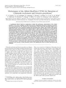
Figure 1. Applications for the detection of ellipses and deformed elliptic shapes: variably grown colonies of bacteria (a) and (b), coded markers on a board for camera calibration procedures (c) and markers on a car for spatial motion tracking and analysis (d). Further author information:
[email protected], Telephone: +49 (0)391 40 90 239
Since special objects can not be identified and segmented by color or texture only, shape analysis provides interesting and promising solutions. We discuss the segmentation and identification of shapes and objects based on their contour. The contours we are looking for are circular or free-formed but in the broadest sense elliptic. We call the corresponding shapes Deformed Elliptic Shapes (DES) (see Figure 1). Our approach uses a mechanism for an automated detection of such DES in real-time. The high speed is required by the considered industrial applications and the speed of the production line. The mathematical description of the shapes we are looking for are mostly unknown. But we don’t want to perform a search for a specific shape but for a class of objects and shapes. Furthermore, the proposed methods describe a fast shape estimator that allows at least a weak differentiation between several classes of shapes. We consider two major steps: presenting a new approach to robustly identify DES in a set of varying objects automatically and in real-time. Furthermore, our method allows us to distinguish between several DES. By extracting and analyzing its contour, we determine if the actual object belongs to a class of interesting objects and forward valid objects to evaluation procedures. We derive the contour using a robust edge estimator and obtain a sorting of the contour points with a region growing approach. The second part focuses on important applications, where a fast detection of DES is required. Taking colonies of bacteria as an example, we describe the extraction of the contour. For the automated segmentation of valid colonies we evaluate the contour, assuming that it is a DES. Additionally, the feasibility of our method is analyzed at the example of detecting coded markers for automated camera calibration on the one hand and a 3D object tracking system on the other.
2. RELATED WORK Image segmentation and shape recognition based on contours is a recurrent application for image processing algorithms. Especially methods of shape analysis and shape matching support classical color and texture based segmentation. For each problem, there are varying algorithms, partially self-learning and adaptive. We consider the detection of deformed elliptic shapes and even the actual research on the detection of ellipses shows, that there is still a potential. Assuming that only the contour of an object is available, there are basic mathematical descriptions based on the area and the perimeter to indirectly check if the contour represents a circle. For general elliptic shapes the following relations in table 1 are valid. shape factor flattening linear eccentricity numerical eccentricity
f0 f e ε
= = = =
b/a (a √ − b)/a a2 − b2 e/a , ε 0 = e/b
compactness roundness elongation bending energy
C R E Ec
= = = =
4π area/perimeter2 4π area/(convex perimeter)2 widthbounding box /heightbounding box 1 L 2 L ∑ p=1 κ(p)
Table 1. General shape descriptors.
It is obvious that the detection based on these mathematical relationships is an extremely fast but also a weak indicator to distinguish between shapes if they only depend on the two ellipse radii a and b, which are approximated by the shortest and longest distance of two points to the center of gravity of the object. More robustness is reached by considering the overall contour behavior. Many existing direct methods for detecting ellipses use a direct Hough transform to distinguish between several elliptic shapes. But the classical Hough transform is very time-consuming and requires precise input data for accuracy and robustness. The generalized Hough transform and its application to machine vision problems, including the detection of circles, ellipses and free-formed shapes is discussed by DAVIS in.1 However, the GHT needs a model decription to search for, and an extension for rotation and scale invariance comes with significantly higher computation time. A fast method of ellipse detection is introduced by X IE. This method takes the advantages of the major axis to find ellipse parameters efficiently. Compared to a Hough transform it only needs a one-dimensional accumulator array to accumulate the length information for the minor axis of the ellipse.2 Further actual methods for a direct and fast detection of mathematical ellipses are considered in.3–6 Contour matching has been approached in a number of ways including the generalized Hough transform,7 wavelet transform8 and Fourier descriptors9 or deformable templates.10 BACHELDER ET AL . propose a scheme that takes partial constraints on the matching between contours in two images and finds the matches using local affine transformations.11
Another algorithm for comparing and matching contours is presented by S ERRA ET AL . They describe a sub-pixel contour matching algorithm using a novel dynamic programming scheme.12 Their approach allows the determination of the optimal continuous path in the generated graph. The matching is obtained as a piecewise parametric function, and a measure of the deformation of the matched contours is possible. Furthermore, they introduce a new general purpose algorithm that allows the optimal geometric match between contours to be determined.13 L EUNG provides a way of incorporating curvilinear grouping into region based image segmentation. Soft contour information is obtained through orientation energy.14 M ALIK ET AL . provide an algorithm for partitioning grayscale images into disjoint regions of coherent brightness and texture.15 Since natural images contain both textured and untextured regions, the cues of contour and texture differences are exploited simultaneously. C OHEN has proposed a formalism to deal with unknown deformations.16 However the implementation is iterative and the use of curvature measures forces a high degree of differentiation along contours, thus requiring contour smoothing. This method offers a good approach but it can not be realized in real-time. The shapes we are looking for are neither real circles nor ellipses but deformed. Methods for a direct ellipse detection won’t be robust enough. Additionally, we don’t know the exact mathematical shape and the texture, so a template matching procedure would also become problematic. Our approach considers the classification of several types of objects and estimates the shape based on the deviation from a standard circle.
3. DETECTING ELLIPTIC SHAPES This section describes the mechanisms to extract the contour of the considered objects. On the one hand the methods use a prior color segmentation for an indirect classification and on the other hand, an edge detector is used to obtain the contour of the objects. After the contours are computed, we apply a classification based on an angular relationship between the normal vector of the contour and its vector to the center of gravity.
3.1. Extracting the Contour Starting from an image which contains the objects we are looking for, our first step is the fast extraction of the contour. Depending on the image quality and the structure of the shape there are at least two possibilities. The first one is performing an image segmentation based on color or texture. Since we know neither the object color nor the exact shape we have to estimate it. We apply an adaptive image binarization based on the mean background color µ. A region is segmented if its variance σ 2 of the estimated background exceeds a predefined value t. Since we use RGB images the difference is the sum of the variances, which are calculated separately for each channel using Eq. (1). If there is any information about the background color then the corresponding probabilities P(xi ) should be weighted differently for each channel. N
σ 2 = ∑ P(xi )(xi − µ)2
,
with P(xi ) = 1
(1)
i=1
As a result there are binary regions of interest, which potentially contain the contours. The fastest way to compute the contour is the evaluation of the edges of the binary boundary in a 8-neighborhood, which is trivial (see Figure 2(b)). If the contour obviously is to short or tends to become very long it is rejected. If a color (or texture) based segmentation is not possible due to unknown information about the objects, then our second way to compute the contour is a direct edge detection. Since we need contours with a thickness of one pixel, the Canny edge detector17 is the best choice, also with regard to robustness (see Figure 2(c)). In one of the first steps of this edge detector a gradient field has to be computed, which is then post-processed with two thresholds by the Canny algorithm. Edge detection in color images can be ambiguous because of contrary edge directions in different channels. Nevertheless, the most popular and fastest approach is to compute the sum of the squared magnitudes of the channels P and the image dimension W (2). P P W ∂ gp (2) ∑ |∇g p |2 = ∑ ∑ ( ∂ xw )2 p=1 w=1 p=1 After all gradients have been computed, the edge tracking procedure evaluates possible and definitive edge position based on the hysteresis thresholds. For efficiency we combined this method with a region growing algorithm that collects
(a)
(b)
(c)
Figure 2. Extracting the contours in image (a) with a simple color based segmentation (b) and the modified Canny edge detector (c).
all points of the edge contour with a known sorting. An alternative segmentation approach based on the human vision system and phase congruency is given in.18 Additionally, S HEN and C ASTAN provide a promising alternative to Canny’s edge detector. While Canny uses an approximation of the derivatives of the Gaussian, Shen/Castan directly apply an infinite symmetric exponential filter (ISEF), which can give a better signal-to-noise ratio.19
3.2. Evaluating the Contour The detection and segmentation of deformed objects is based on the contours continuity. The basic approach is to measure the deviation from a circle and uses its unique properties. Therefore we define a deformed elliptic shape as a shape with an at least elliptic contour with moderate deformation. That means, its center of gravity is central and inside the contour. This constraint allows a very fast approach for the detection of deformed circles and ellipses. A contour can be described using its curvature and tangential behavior as it is done by many template matching algorithms. A local analysis for neighboring points of a contour is ambiguous and leads to no meaningful global conclusion about the shape. For example there are similar neighboring tangents for rectangles and triangles, because they consist of line segments. For our similarity measures we compare the actual contour of a shape against a circle as a special type of an ellipse. The matching of an unknown and free-formed DES against a circle uses the basic principles of the nonlinear matching distance. There are two finite sets of ordered contour points A and B with A = {a1 , ..., am } and B = {b1 , ..., bn }. Let f be the correspondence function between all points in set A and all points in set B such that there are no ai < ai+1 , with f (ai ) > f (ai+1 ). The stretch s(ai , b j ) of (ai , f (ai ) = b j ) is 1 if either f (ai ) = b j or f (ai ) = b j−1 , or 0 otherwise. The nonlinear elastic matching distance NEM(A, B) is the minimum over all correspondences f of ∑ s(ai , b j ) + d(ai , b j ), with d(ai , b j ) the difference between the tangent angles at ai and b j . The robustness and the optimal matching strongly depends on the tangent vectors of the two contours. Therefore, we use a circle as the optimal matching contour and make use of some of its unique properties. The center point of a circle is its center of gravity, the radius vector is always the normal vector of the contour and has an angle of π to the tangents of the contour, respectively. The more the contour becomes elliptic, the more neighboring tangents change and, finally, the higher becomes the angle between gradient and radius vector (see Figure 3).
g1
a1
deformed elliptic shape
m1 cgravity m2 a2 g2
n1 t1
Figure 3. Computing the Shape Angle Dα of a deformed contour. The basis are the center of gravity, the tangents ti and the vectors mi from each point of the contour to the center. The Shape Angle is computed based on the angles αi between mi and the gradient vectors gi .
Considering only local tangent vector changes is very sensitive to outliers and thus, not robust enough. Therefore we additionally use the center of gravity as a central point, that is equal for all points of the contour. A central point stabilizes the calculation notedly. Thus, we calculate the sum of all the deviation angles αi between the gradient vectors ~gi and the vectors from each contour point to the center of gravity m ~ i using equation (3). The mean value of all αi is a sufficient approximation for the quantity of the deviation from a circle. Dα =
~gi ~mi 1 N−1 ∑ arccos (~gi · ~mi ); ~gi = |~gi | and ~mi = |~mi | N i=0
(3)
Assuming the objects contour is a circle, then Dα is zero, because αi is zero at all positions. The maximum angle is π, because the gradient is always perpendicular to the line itself. By using each single measured point of the contour, a high robustness is achieved. We do not allow that the center of gravity exists outside of the contour. In this case, our method will not work reliably. Therefore, an additional point-in-polygon test assures that no objects are classified as valid if their contour is obviously not circular or elliptic. This method also works for discontinuous contours, presumed that its center is inside. Statistically, the median is a better estimator than the mean, but it is more time-consuming. It is a robust estimation based on linear combinations of order statistics (L-estimate). The median of a statistical distribution with cumulative distribution function D(x) is the value x so that D(x) = 1/2. For a nearly regular deformed contour, the values αi are distributed symmetrically and the median is therefore equal to the mean. The efficiency of the median, measured as the ratio of the variance of the mean to the variance of the median, depends on the sample size N ≡ 2n + 1 as 4n/π(2n + 1) which tends to converge to 2/π if N becomes large. Although, the median is less time efficient than the mean, it is less sensitive to outliers. For a small number of values the median can be computed based on a prior sorting. Thus, the complexity is O(nlogn). If there are a lot of values to compare this can be time-critical. The fastest general method is selection and partitioning as it is done in the Quicksort algorithm and reduces the complexity to O(n).
(a)
(b)
(c)
Figure 4. Sections of petri dishes with different kinds of bacteria colonies. Evaluable colonies must be elliptic (marked white) otherwise different colonies merged (marked gray).
This general approach is robust against lines, curve segments and arbitrary contours and preserves its high recognition rate even if the contour is open up to 15%. Furthermore this method ensures the invariance against rotation and scaling due to the usage of angular relationships rather than distances. High performance is reached by multiple using gradient information for both the edges and the computation of the shape angle. The only difference between color and grayscale processing is the edge detection. Thereafter we just have to process sorted contours. Besides the efficiency on the one hand, the robustness decreases for ellipses and deformed shapes that have a ratio smaller than about 1:4 between the major axes. ∞ ∞ 1 F(x) = a0 + ∑ an cos nx + ∑ bn sin nx 2 n=1 n=1
(4)
(a)22.54
(b)76.07
(c)05.35
(d)89.00
(e)57.26
(f)30.41
(g)30.73
(h)33.87
(i)35.11
(j)70.30
(k)53.72
(l)39.52
Table 2. Images generated from synthetic contours with the corresponding Dα (in degree) based on the median. Smaller deviations from the theoretical value are due to rasterization.
In some cases the image consists of a wide variety of objects, including elliptic shapes but also triangular, rectangular and arbitrary boundaries. A robust segmentation and differentiation between this kind of objects is possible by changing to polar coordinates and using a harmonic analysis of the contours. Therefore we have to compute the Fourier series of the contours with respect to the center of gravity. The 1st two harmonics determine the deviation from circle and ellipse and the third from a triangle and so on. This method is also invariant against rotations and can be computed very efficiently but requires nearly convex objects. The Generalized Fourier Series is given by equation 4. We applied our approach to synthetic images and tested a variety of images taken from our industrial applications, which we will introduce in Section 4.
3.3. Test Results Additionally we generated a set of geometric objects to verify our methods. Table 2 shows several geometrical primitives, deformed shapes and other special geometries including the results based on the median deviation angle Dα . The results also show that typical, deformed elliptical shapes have a Dα ≈ π6 . The more the shapes become circular the less Dα becomes. Objects with complex and square-edged structures show a notedly higher value. Solely the square itself seems to be a problem, but otherwise its contour is very regular. Practically, we have to detect DES among lots of artifacts and exact regular structures are very rare (see Section 4). Looking at Table 2(i), there is a free formed object which value indicates, that the contour may be a DES. But this object does not satisfy the criteria for a DES, because its center of gravity is outside the contour (see Sec. 3.2). In addition, the results also show that it may be possible to distinguish between contours, that represent a circle, a DES, a rectangle and a line. Otherwise, it is not possible to distinguish between all shapes. But we remark, that this approach is not designed to classify objects but to distinguish between artifacts and circular or deformed elliptic contours. A direct and robust classification for stars, triangles, squares and lines may be based on templates or on representations in polar coordinates like a harmonic analysis as described in the last section.
4. APPLICATIONS This section shows three exemplary applications where a fast detection of ellipses and deformed elliptic shapes is required. The first example is the recognition of bacteria colonies in a production line. The second example explains the identification of coded markers for a precise and full automated camera calibration procedure. The last one describes the fast detection of coded markers in an industrial environment for a 3D tracking of cars and robots in real-time. We used 1.3 Mpix images for color and grayscale and a standard PC Pentium IV with 2GHz. One essential part for the use of the proposed methods in this areas is the automation. Additionally, it allows the applications work reliable with high speeds. The detailed internal methods and procedures of the applications itself are not part of this work.
4.1. Bacteria Colony Recognition For the analysis of possible diseases, colonies of bacteria should be analyzed automatically. Therefore a method was required, which selects appropriate colonies. The considered bacteria live on an agar and slowly begin to proliferate until they form a colony. Single colonies of bacteria uniformly grow in all directions. In this ideal case, the resulting contour is a circle. Practically, the shape of a colony is a deformed ellipse, depending on their natural growing behavior. A robot automatically picks a colony and transfers a probe to an external biological analyzer. Sometimes colonies, which are near to each other, tend to merge. But for a reliable analysis it is necessary to assure that the robot only picks authentic biological populations. A color based segmentation of authentic colonies is not possible, because there are different bacteria with the same color. The only criteria to distinguish authentic colonies is their shape, and the contours are neither a circle nor an ellipse but a deformed elliptic shape (DES).
(a) authentic.
(b) authentic.
(c) authentic.
(d) mixed.
Figure 5. Sections of images with colonies of bacteria grown on different agars.
Figures 5 and 4 clearly illustrate the problem for an automated shape analysis. Within this application no information about the background is available (e. g.color of the agar), and since texture can not be used to classify colonies, the deformed shapes must be used. The colonies in Fig. 5(a) – 5(c) are authentic and the colony in Fig. 5(d) consists of several species of bacteria with the same color. The user wants to known how many different authentic and how many mixed colonies there are. We successfully applied our methods and reached a detection/classification rate in the fully automated processing at an average of 98 %. An additional differentiation between authentic and mixed colonies (based on color and texture variances) is done afterwards. The average number of potential objects is 40 and the average number of valid colonies is 20. Detecting and evaluating the deformed shapes in the color images is done in about 230 ms, which can be said to be real-time for this purpose.
4.2. Automated Camera Calibration Another application where an ellipse detection is required is camera calibration. There are many commercial camera calibration tools. Their main capability is their precise mathematical calculation of the extrinsic and intrinsic parameters. Actual image processing methods use some additional information projected or manually brought to the objects surface. On this basis, the transformation from the world to the image space can be reconstructed. To achieve a high precision, as many as possible transformation parameters have to be determined. A common method for calibrating camera systems is to use boards and prismatic objects with coded markers. With the known code of each marker, a unique mapping from the world to the image coordinate system is possible. While a lot of tools require a manual picking of the markers, we examined several methods for an automated camera calibration. The coded markers we used were first introduced by A HN in.20 A locomotor system translates and rotates a calibration field and the markers are detected (Fig. 6(c)). Their contour is extracted using a Canny edge detector. The precision of the calibration strongly depends on the precision of the markers in the image. The goal is to find an ellipse which optimally represents a given set of points. Therefore, we use an iterative ellipse fitting algorithm.21 This procedure uses a least squares method based on the perpendicular distance. Starting from seed values, defined by the contour, an iterative approach fits an ellipse with sub-pixel precision to the contour points. Another self-learning method uses bootstraps. Thus, not the entire contour is used for the fitting but parts of an ellipse are determined, which finally results in one set of ellipse parameters. However, camera calibration needs rarely to be done in real-time, even
(a) original.
(b) Canny edges.
(c) result.
Figure 6. Section of a larger marker board (a) and the edge based shape detection (b) and (c).
if it is done automatically. But increasing the performance of algorithms is always desirable. Furthermore, many of the iterative ellipse fitting methods require well distributed input data, otherwise they won’t converge. So, before we apply any ellipse fitting procedures to all possible objects, we first segment obviously elliptical shapes from artifacts using our DES approach. This increases the computation speed for the entire procedure up to 300% and notedly stabilizes the fitting. The detection of 40 different and elliptical distorted markers among more than 130 objects (40 markers, 40 rectangles and artifacts) takes about 150 ms and 330ms with ellipse fitting.
4.3. 3D Position Tracking The third industrial application also deals with coded markers. These markers are used for a real-time tracking of cars and robots. Spatial calibrated cameras are permanently observing a car. The actual position is calculated based on the positions of the coded markers. The challenges for the image processing are the permanently varying objects in the field of view and
(a)
(b)
(c)
Figure 7. Detection of coded markers on a moving car from different viewing directions.
the lighting conditions. Furthermore, the coded markers appear and disappear, depending on their actual spatial position with respect to the position of the cameras. The center of gravity of the determined DES is a sufficient approximation for this application. Ellipse fitting would increase the precision but at the cost of the overall processing speed. The detection of the DES is done in real-time and averages out at 210 ms per image, which allows an object tracking of about 35 markers with 5 images per second. This approached is furthermore extended to motion tracking of an automated welding robot in an industrial environment.22 Additionally, the computation speed can be drastically increased if a search is only performed in a defined range that changes between two images in a sequence.
5. SUMMARY We presented a universal detector for circles, ellipses and deformed elliptical shapes (DES) for real-time applications. A contour evaluation of the tangential behavior and based on a comparison to a circle allows the fast computation of a deviation quantity, which is finally used to separate elliptical shapes from artifacts. The contours are extracted with a modified edge detector, that collects objects while connecting edge pixels. Finally, we verified our methods as well as on synthetic data as under industrial conditions and successfully integrated the algorithm.
REFERENCES 1. E. R. Davis, Machine Vision : Theory, Algorithms, Practicalities, ch. The Hough Transform and Its Nature, pp. 245– 268. Signal Processing and its Applications, Academic Press, San Diego, London, 2 ed., 1997. 2. Xie, Y. and Ji, Q., “A new Efficient Ellipse Detection Method,” in International Conference on Pattern Recognition 2002, pp. II: 957–960, 2002. 3. Zhu, C. and Wang, R., “A fast Automatic Extraction Algorithm of Elliptic Object Groups from Remote Sensing Images,” Pattern Recognition Letter 25, pp. 1471–1478, October 2004. 4. Zhang, S.C. and Liu, Z.Q., “A Robust, real-time Ellipse Detector,” Pattern Recognition 38, pp. 273–287, February 2005. 5. Yao, J. and Kharma, N. and Grogono, P., “Fast Robust GA-based Ellipse Detection,” in International Conference on Pattern Recognition 2004, pp. II: 859–862, 2004. 6. Lei, Y. and Wong, K.C., “Ellipse Detection based on Symmetry,” Pattern Recognition Letter 20, pp. 41–47, January 1999. 7. D. H. Ballard, “Generalized Hough Transform to Detect Arbitrary Patterns,” IEEE Transactions on Pattern Analysis and Machine Intelligence 13(2), pp. 111–122, 1981. 8. C. Jacobs and A. Finkelstein and D. Salesin, “Fast multiresolution image querying,” in Proceedings of SIGGRAPH 95, Proceedings SIGGRAPH , pp. 277–286, 1995. 9. S. Loncaric, “A Survey of Shape Analysis Techniques,” Pattern Recognition 31(8), pp. 983–1001, 1998. 10. Stan Sclaroff and Alex P. Pentland, “Modal matching for correspondence and recognition,” IEEE Transactions on Pattern Analysis and Machine Intelligence 17, pp. 545–561, jun 1995. 11. Bachelder, I.A. and Ullman, S., “Contour Matching Using Local Affine Transformations,” in Proc. of Computer Vision and Pattern Recognition, CVPR , pp. 798–801, 1992. 12. Bruno Serra and Marc Berthod, “Subpixel Contour Matching Using Continuous Dynamic Programming,” in Proceedings on Conference on Computer Vision and Pattern Recognition (ICVPR), pp. 202–207, (Seattle), 1994. 13. Bruno Serra and Marc Berthod, “Optimal Subpixel Matching of Contour Chains and Segments,” in ICCV, pp. 402– 407, 1995. 14. Thomas Leung and Jitendra Malik, “Contour continuity in region based image segmentation,” Lecture Notes in Computer Science 1406, pp. 544–559, 1998. 15. Jitendra Malik and Serge Belongie and Thomas K. Leung and Jianbo Shi, “Contour and Texture Analysis for Image Segmentation,” International Journal of Computer Vision 43(1), pp. 7–27, 2001. 16. I. Cohen and N. Ayache and P. Sulger, “Tracking Points on Deformable Objects Using Curvature Information,” in 2nd European Conference on Computer Vision (ECCV’92), pp. 458–466, (Santa Margherita Ligure, Italy), May 1992. In Lecture Notes in Computer Science: Computer Vision – ECCV92, Vol. 588 Springer-Verlag. 17. J. Canny, “A Computational Approach to Edge Detection,” IEEE Transactions on Pattern Analysis and Machine Intelligence PAMI-8(6), pp. 679–698, 1986. 18. Xu Jie and Shi Peng-fei, “Natural color image segmentation,” in Proc. of Int.l Conf on Image Processing ICIP (Barcelona, Catalonia, Spain, September 14–18, 2003), 1, pp. 973–976, 2003. 19. J. Shen and S. Castan, “An optimal linear operator for step edge detection,” Computer Vision, Graphics, and Image Processing: Graphical Models and Understanding 54(2), pp. 112–133, 1992. 20. Sung Joon Ahn, “Kreisförmige Zielmarke (Circular Target),” in Proc. of 4. ABW-Workshop Optische 3DFormerfassung (Esslingen, Germany, 22–23 January, 1997), Technical Academy Esslingen, 1997. 21. Sung Joon Ahn and Wolfgang Rauh and Matthias Recknagel, “Geometric Fitting of Line, Plane, Circle, Sphere, and Ellipse,” in Proc. of 6. ABW-Workshop Optische 3D-Formerfassung (Esslingen, Germany, 25–26 January, 1999), Technical Academy Esslingen, 1999. 22. Dirk Berndt and Axel Fix and Erik Trostmann and Christian Teutsch, “3-D Image Processing as the Key for a Flexible Manufacturing Cell for the Automated Welding of Large Steel Structures,” in Proc. of Optical 3-D Measurement Techniques VII (Vienna, Austria, October 3–5, 2005), Armin Gruen and Heribert Kahmen, ed., 1, pp. 317–326, TU Vienna, ETH Zurich, (Vienna), 2005.