for Si wafer temperature measurements using its rough backsurf ace, as part of an Small Business Innovation Research (SBIR) program funded by the National ...
Real-time image processing techniques for noncontact temperature measurement Michael K. Lang University of New Mexico Center for High Technology Materials Albuquerque, New Mexico 87131
Gregory W. Donohoe University of New Mexico Department of Electrical and Computer Engineering Albuquerque, New Mexico 87131
Saleem H. Zaidi University of New Mexico Center for High Technology Materials Albuquerque, New Mexico 87131
Abstract. A noncontact temperature measurement technique based on thermal expansion of materials is presented. The technique, diffractionorder spot analysis, is based on monitoring diffraction angle variations due to grating expansion. Because of the pressing need for noncontact temperature measurements during semiconductor processing, silicon was chosen as the demonstration material. The diffraction method requires a grating of suitable spatial frequency etched onto the surface of the Si wafer. Two symmetrically disposed incident beams are used to provide a differential measurement that is independent of sample tilt to the first order. An automated data acquisition and analysis system was
developed for continuous monitoring of two diffraction-order angles. From the order separation, a relative temperature change can be calculated in near real time. Image processing techniques based on centroid operation were used to calculate diffraction-order displacement with subpixel accuracy. For comparison with optical data, simultaneous temperature measurements from a thermocouple bonded to the Si sample
Steven R. J. Brueck
were recorded. Good agreement between optical and thermocouple
University of New Mexico Center for High Technology Materials and Department of Electrical and Computer Engineering and Department of Physics and Astronomy Albuquerque, New Mexico 87131
measurements was obtained. Temperature resolution was inversely proportional to the number of grating lines. A resolution of 0.37°C is demonstrated for a 3000-line grating over a 20 to 750°C temperature range. Subject terms: noncontact temperature; gratings; thermal expansion. Optical Engineering 33(10), 3465-3471 (October 1994).
1 Introduction Rapid, accurate, noncontact temperature measurements are
a pervasive industrial need. In the semiconductor industry, precise temperature control is needed for processes such as diffusion, ion implantation, annealing, and film growth. The rapidly diminishing thermal budgets that follow from decreasing lateral dimensions of Si integrated circuits are leading to a demand for more accurate, faster response, noncon-
tact temperature sensing. The most commonly used temperature devices in industry are thermocouples, thermistors, and pyrometers. Thermistors and thermocouples (TCs) are direct contact methods of temperature measurement. Because of contamination and the direct thermal contact with the surface, they are best suited for calibration rather than real-time process control. Two classes of noncontact measurements are blackbody radiation and thermal expansion. Pyrometers and other IR detectors use the radiation emitted from a surface to determine absolute temperature. Pyrometers depend on three main variables: emissivity, field ofview, and the optical properties of the surface.1'2 The field of view is important since these measuring devices average the temperature values of any object in the view. The surface emissivity is often affected by complex multilayered and patterned substrates.3 Several investigations incorporating real-time emissivity correction Paper 05014 received Jan. 11, 1994; revised manuscript received Apr. 16, 1994; accepted for publication Apr. 16, 1994. 1994 Society of Photo-Optical Instrumentation Engineers. 0091-3286/94/$6.00.
along the pyrometry are under way. The thermal expansion coefficient of a Si wafer is independent of process variations
to the first order; therefore, the thermal expansion measurement methods provide an alternative route to temperature measurement techniques.
In recent years, several temperature sensing schemes based on thermal expansion of the semiconductor wafer have been developed. Donnelly4 developed an JR interferometric
technique based on transmission through the wafer. This method requires both sides of the wafer to be polished, is limited at high temperatures by free carrier absorption, and is also susceptible to process variations due to either topography or thin-film interference effects. Zaidi, Brueck, and
McNeil5 developed a temperature measurement scheme based on projection moire interferometry requiring a grating Si wafer. Here we report on a variation of this method using image processing techniques to monitor the angular positions of laser beams diffracted from the grating to determine surface temperature in near real time. 2
Grating Expansion Technique
The grating method uses the angular positions of diffraction
orders to monitor the thermal expansion of a grating. Knowledge of the linear expansion coefficient of a material enables
us to determine a change in temperature by measuring the change in length. If a relative temperature LT results in a change IXL of a material with an initial length L0, then the linear expansion coefficient a is given by OPTICAL ENGINEERING/October 1994/Vol. 33 No. 10/3465
LANG et al.
1
zL
1st Order (m=-1)
a=—-— .
1st Order (m=-1)
(1)
L0 T
The scale of length used here is the period of the grating etched on the surface of the Si wafer. Angular positions of the diffraction orders produced by an incident beam on the grating surface are governed by the grating equation mX . . sinO1 = sinOm + —i- ,
(2) Fig. 1 Experimental configuration for grating temperature measure-
where d is the period of the grating, X is the incident light
ments by monitoring two — 1 diffraction orders.
wavelength, O is the incident angle, m is the order of the diffraction, and Om is the diffraction angle. The change in angular position ofthe order with temperature is simply given by
Mm
mXo
(3)
TdcosO1
For the experiment reported here, the grating period, optical wavelength, and incident angle are chosen so that the — 1 diffraction orders emerge approximately normal to the wafer surface. Two beams are symmetrically incident on the wafer at equal but opposite angles, as shown in Fig. 1 . This geometry is differential in that the angular separation between the two — 1 diffraction orders is independent of the wafer tilt to the first order. If diffraction orders are focused by a lens of focal length F, then the small diffraction-order dis-
placement Y(T) is simply given by FO(T). For two — 1 diffraction orders moving in opposite directions, the separation is twice L\Y(T), and the measured temperature is given by
TT.+ f i 2aXFzY
(4)
where ':f and T1 are the final and initial temperatures, re-
spectively. In general, the thermal expansion coefficient a is a function of temperature. For silicon, a has been well characterized in the range of interest, 20 to 1000°C. The functional form of a used for calculating T is given by
a=(a{1 —expb(T--T0)]}+cT)X 1O_6
[K']
,
(5)
where a=3.725, b= —5.88X10³, c=5.548X10⁴, and T0= 124 (Ref. 6).
ordinates for each diffraction spot are determined to measure the distance between them to calculate temperature in near real time (—2 s per measurement).
4 Calibration and Temperature Calculation For temperature calculation using Eq. (4), a few parameters
have to be determined, i.e., the initial separation LY, initial temperature T1, and F. The initial temperature is obtained from the TC on the sample, and the initial separation is from the first frame processed. The focal length F is determined by one of two alternate methods depending on the relative size of the grating and the beam diameter. If the grating is smaller than the beam diameter, then the edges of the grating area act as a rectangular slit. This results in the diffraction spots having the shape of a sinc2 function. The focal length F of the optical system is simply related to the grating width L by7
xL F=— 3X
(6)
where x is the separation in pixels between the two sec-
ondary maxima. For a 8.8- X 6.6-mm2 CCD array of 640 X 480 pixels, one pixel corresponds to 1 3.75 pm. In general we prefer to block one of the diffraction orders for the calibration step, because of the interference effects of the
two orders. Figure 2 shows an example of the sinc pattern obtained from a 500- X 5OO-im2 grating area. For a grating width larger than the beam diameter, a grating mask with a known period was placed before the imaging optics. For the diffraction pattern of a sinusoidal amplitude grating, the pixel distance between the first secondary maxima is related to the focal length F by 8
3 Experimental Setup
d
tx
An interferometrically defined 1 .O-pm period grating is etched onto the Si wafer and is placed on a copper block
F=—-- ,
embedded with a resistive cartridge heater in a vacuum cham-
where d is the period of the grating mask. Once F is determined using either Eq. (6) or (7), no other changes are made in the optical configuration for the duration of measurement.
ber. A TE-polarized He-Ne laser beam (X = 0.633 m) is split into two parts that are incident on the sample at angles o 39.25 deg such that — 1 diffraction orders ofthe grating are approximately normal to the grating surface. For an independent calibration of this optical technique, a TC is bonded to the sample for in-contact temperature measurements. A data acquisition system consisting of a 486-based
computer system with video capture system (DT2867, DT2821) was used to monitor continuously diffraction-order separation and calculate the temperature difference. The co3466 / OPTICAL ENGINEERING / October 1994/ Vol. 33 No. 10
5
(7)
Diffraction Spot Analysis
The temperature measurement relies on tracking the changing
distance between the diffraction spots. To achieve resolution of better than 1°C, the center of the spots must be evaluated with subpixel accuracy. The steps taken to process the images into temperature information are the following:
REAL-TIME IMAGE PROCESSING TECHNIQUES FOR NONCONTACT TEMPERATURE MEASUREMENT
/
\*
Fig. 3 Spot boundary estimation technique used in centroid calculations.
0 oQ
oQ
Fig. 2 CCD image of 500- x 500-p.m2 grating used for calibrating the effective focal length F of the optical system.
Reduce image noise. 2. Locate spots in image. 3. Estimate centers with subpixel resolution. 1.
To reduce noise, several methods were employed. A 3 X 3 or 5 X 5 neighborhood averaging kernel was used to smooth the data before the search for the maximum. This is effective in reducing the effects of camera faults, where individual pixels can be stuck at a fixed value, and the effects of white noise. Another method examined to reduce noise was a background noise subtraction. For this, the diffraction beams were blocked and a frame was acquired to cancel fixed pattern noise due to nonuniformity in the CCD array. To locate the spots, a search for the maximum pixel in the image is performed, then the spot is extracted from the image, and the procedure is repeated for the second spot. To extract the spots,
line scans are taken from the coordinates of the two pixel maxima through the image in four or eight directions, as shown in Fig. 3. Linescan thresholds are used to define the extent of the spot area. The values are examined according to a threshold value and a count of the values below the threshold. Values below the threshold are clipped to zero to separate the spots. Figure 4 shows a line scan through the two peaks and shows how the threshold value can affect estimated spot boundaries. With the spot areas identified, a centroid calculation is applied to find the subpixel coordinates of the diffraction-order spot centers. Three different methods
for subpixel spot center location were implemented: a centroid calculation, a 1 -D matched filter and a 2-D matched filter.8 Other methods such as wide-aperture linear array averaging techniques9 are not feasible because of the large motion of the spots due to wafer motion during heating. The matched filters showed small improvements over the centroid method but at a large cost in time for computation.'° This left the centroid calculation as a time efficient choice.
Best Threshold
Qo
Fig. 4 Effects of threshold values on two —1 diffraction-order separations.
5.1 Centroid Calculation A centroid approach is an appropriate measure to estimate the spot centers due to the angular symmetry of the two incident Gaussian beams on the grating area. The centroid calculation is carried out by using a weighted average of intensity values as defined below:
-x— xy x.i(x,y)
>:>: i(x,y)'
-y=
(8)
y.i(x,y) •
x y i(x,y)
is the intensity of the pixel at location (x,y) and :where i(x,y) are the resulting estimated subpixel centroid coorand
dinates. These coordinates represent a fraction (—1/10) of a
pixel on the CCD camera. This subpixel resolution was achieved by using the distribution of the intensities over the CCD elements. As the shape or intensities of the spot shift,
the center of the spot shifts accordingly. Using a similar approach, resolution greater than 1/100 of a pixel has been
rt1'12
6
Experimental Results The technique was applied to five samples with different grating areas: 3 X 3 mm2, 1 X 1 mm2, 500 X 500 pm2, 125 x 125 pm2, and 500 X 100 m2, all with a 1-pm period. The different sizes were used to investigate the relation between the width of an illuminated grating and the temperature resolution. The nonsymmetric 500- X 1O0pm2 sample results OPTICAL ENGINEERING / October 1994 / Vol. 33 No. 10 / 3467
LANG et al.
in elliptical spots as shown in Fig. 5 and was used to demonstrate that the width of the grating is the dimension determining resolution. For an independent comparison with the optical data, temperatures were acquired simultaneously from a TC bonded to each sample. Each TC data point is averaged from a thousand analog-to-digital conversions. Two basic measurements were performed on each sample: a high-temperature run and a mm-
Fig. 5 CCD image of two —1 diffraction orders from a 500- x 100im2 grating.
imum accuracy run. Figure 6 shows high-temperature measurements for grating widths varying from 1 to 0.125 mm. There is good agreement between optical and TC measurements. The most significant difference is during the temperature ramping when the optical temperature is below the TC temperature. This is probably due to the surface emissivity variation between the Si and the bonding cement used to hold the TC to the Si. Once thermal equilibrium is reached, TC and optical measurements agree well. At higher temperatures, signal noise increases due to air turbulence above the chamber. To estimate the accuracy of the optical technique, minimum temperature measurements were carried out. The mean absolute difference (rms) between the optical and TC data was taken over a small temperature range to find the differ-
600 500 500 400 400 300 300
200
200
100
100
0L) 0
200
400
600
800
1000
1200
a
0 ci)
E
600
600
500
500
400
400
300
300
200
200
100
100
ci)
0
200
400
600
800
1000
Time (seconds) 0 Optical
-— TC
Fig. 6 Comparison between TC and optical temperature measurements for (a) 1 -mm2, (b) 0.25-mm2, (c), 0.05-mm2, and (d) 0.016-mm2 area gratings. Note the decreasing temperature accuracy with area.
3468 I OPTICAL ENGINEERING I October 1994/ Vol. 33 No. 10
REAL-TIME IMAGE PROCESSING TECHNIQUES FOR NONCONTACT TEMPERATURE MEASUREMENT
ence between the two measurements. The widest grating sam-
pie, 3 mm, had the least error, 0.74°C ( 0.37°C), and the maximum error of 2.45°C was over the 56 to 72°C range as shown in Fig. 7. The 1-mm sample showed a mean error of 4.52°C with a maximum error of 8.3°C. The 5OO-im sample has a mean error of 7.44°C and a maximum error of 15.10°C. The 125-rim sample was the noisiest, the mean error being 21.97°C, the maximum error being 55.88°C. Figure 8 shows the variation of accuracy with the grating width for the sampies measured. The solid line in Fig. 8 represents a fit to the experimental data points given by 1.45 + 2.42/x, where x is the grating width. This is in good agreement with all grating measurements, where resolution decreases with a decreasing number of grating lines.
Improvement in the SNR can be carried out either by software or hardware. One software method of decreasing signal noise is frame averaging. Frame averaging was used to decrease the effect of white background noise, vibrations, and any other uncorrelated transient interference. The results of frame averaging are shown in Fig. 9. The data were taken with no temperature change. The mean error was reduced from 4.37 to 0.87°C by averaging 25 frames (1-mm sample); additional averaging from 25 to 256 frames gives an improvement of only .02°C. This suggests that the frequency
of the optical system noise is of the order of a second. Averaging the spot separation is another method of increasing the precision. This is equivalent to averaging the calculated temperature value, as is done with the TC values. Processing a single frame for spot separation took on the order of 2 s. Averaging 100 distances over approximately 30 mm gives only eight temperature values. One way of accurate comparison between optical and TC measurement is to compare unaveraged measurements by both techniques. Figure 10 displays the unaveraged data for the 1 -mm sample and shows that the optical measurement is comparable. The major sources of noise are the convective turbulence in the air above the sample and the contact heating of the wafer over the copper block. By incorporating a fan to force a laminar flow above the heating chamber, convective turbulence can be significantly reduced. To avoid contact heating of the sample, a radiative method was used in which samples were placed on a quartz block with a heating element
below, but not in contact with the quartz block. Figure 11 shows a typical temperature measurement with radiative heat-
Effects of Frame Averaging C-) C-)
E
0
72 70
a) C)
68
a)
a)
66 64
E 62
a)
60
0 0
58
0
10
20
30
50
40
56
Time (sec)
o No Averaging (2 seconds) • 25 Frames Averaged per Data Point (3 seconds) v 256 Frames Averaged per Data Point (10.5 seconds)
Fig. 7 Low temperature measurements for 3-mm-wide grating for minimum temperature resolution.
Fig. 9 Influence of frame averaging on temperature measurements.
Sample Width vs. Average Error
100
90 80 70 60 50
040
30
18
100
a 90 E 80
.
300
400
500
600
700
400
500
600
700
Optical Diffraction Technique (No Averaging)
70
a)
200
60 50 40 30
0
1
2
3
4
Sample Width (mm)
Fig. 8 Variation of average temperature error with the grating width. Comparison is made with TC measurements.
0
100
200
300
Time (sec) Fig. 10 Low temperature comparison between (top) IC and (bottom) optical temperature measurements without averaging.
OPTICAL ENGINEERING / October 1994 / Vol. 33 No. 10 / 3469
LANG et al.
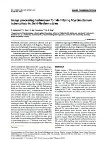
3. T. Sato, ' 'Spectral emissivity of silicon," J. Appl. Phys. 6,
339—347
(1967).
4. V. M. Donnelly, ' 'Infrared laser interferometric thermometry: a non-
0)1))
I 7))
(a)
C.)
intrusive technique for measuring semiconductor wafer temperatures," J. Vac. Sci. Technol. A 8, 84—92 (1990). 5. S. Zaidi, S. Brueck, and R. McNeil, ' 'Non-contact, .1°C resolution temperature measurement by projection moire interferometry,' ' J. Vac. Sci. Technol. B 10, 166—169 (1992). 6. Y. Okada and Y. Tokumaru, ' 'Precise determination oflattice parameter and thermal expansion coefficient of silicon between 300 and 1500 K," J. AppI. Phys. 56, 314—320 (1984).
7. J. W. Goodman, Introduction to Fourier Optics, McGraw Hill, New York (1968). 8. F. Stremler, Introduction to Communication Systems, Addison-Wesley, Reading, MA (1982). 9. P. Cielo and G. Vaudreuil, ' 'Algorithm for subpixel edge positioning and part sizing under coherent projection,' ' Opt. Laser Technol. 23,
10)) (311()
E
E2 01))
85—95 (1991).
:14)) 10.
(b)
0 200 400 600 600 1000 Time (see)
• Optical
M. Lang, ' 'Real time image processing techniques applied to non-
contact temperature measurements,' ' Masters Thesis, University of New Mexico (July 1992). 1 1 . P. Seitz, ' 'Optical superresolution using solid-state cameras and digital signal processing,' ' Opt. Eng. 27(7), 535—540 (1988). 12. N. G. Alexander, ' 'Elimination of systematic error in subpixel accuracy centroid estimation,' ' Opt. Eng. 30(9), 1320-1330 (1991).
Fig. 11 Optical and TC temperature measurements using radiative heating (a) without laminar flow and (b) with laminar flow.
Michael K. Lang received his BS in computer engineering in 1988 and his MS in electrical engineering in 1992, both from the University of New Mexico. He is cur-
ing up to approximately 800°C without [Fig. 11(a)] and with [Fig. 11(b)] laminar flow showing improved agreement with the TC values.
rently employed as the systems programmer for the Center for High Technology. Interests include image processing, auto-
7 Summary A noncontact temperature measurement technique based on thermal expansion of a grating etched in Si has been investigated. Angular positions of the diffraction orders are monitored as the grating period changes. A near real-time system for diffraction-order spot analysis based on centroid calculations has been implemented. A calibration method using the internal structure in the diffraction-order spot images has been developed to determine the effective focal length of the imaging system. Filtering and averaging methods were used to improve the precision. The temperature resolution demonstrated was inversely proportional to the grating width.
Temperature accuracy of 0.37°C was demonstrated for a 3-mm-wide grating, and temperature measurements were recorded from room temperature to approximately 800°C. For further improvements in precision, the diffraction spots could be magnified to decrease the degrees Celsius per pixel ratio, and a commercially available CCD with more photodetectors
mation of manufacturing, computer graph-
cs, user interfaces, and computer-
assisted education.
Gregory W. Donohoe received his PhD in electrical engineering from the University
of New Mexico in 1989. From 1976 to 1989, he was with Sandia National Laboratories doing research and development
in seismic signal analysis, night vision, real-time motion detection, synthetic aperture radar pattern recognition, and machine vision. Since 1990 he has been an assistant professor in electrical and computer engineering at the University of New Mexico, where he teaches courses on digital hardware design, image processing, and vision. His research interests include applications of machine vision to scientific, medical and industrial problems, and the study of biological vision processes.
,
. ,,/
per inch could be employed. To automate the process, al-
Saleem H. Zaidi completed his PhD in
gorithms for autocalibration and determination of the thresholds could be developed, and an iterative algorithm could be used to adjust the threshold until only two objects are found.
in 1989. His PhD work was on interferometric grating fabrication and optical cou-
The time of centroid calculation could be significantly reduced from 2 s currently to subseconds by optimizing the software and using a compiler that supports a flat memory model. Acknowledgment Support for this work was provided by SRC as part of the New Mexico SEMATECH Center of Excellence in Metrology and On-Line Analysis for Semiconductor Manufacturing.
References 1. T. J. Quinn, Temperature, 2nd ed., Academic Press, New York (1990). 2. OS 900 Series Infrared Thermometer Operators Manual, Omega Engineering Inc., Stamford, CT (1987).
3470 I OPTICAL ENGINEERING I October 1 994 I Vol. 33 No. 10
physics from the University of New Mexico
pling to surface plasma waves. Since graduation, he has worked as a research scientist at the Center for High Technology Materials on applications of sub-micron gratings in semiconductor processing. He has developed optical, noncontact techniques for characterization of metal films, lithographic alignment and overlay measurements, and temperature measurements of Si wafers. He has developed multiple exposure interferometric techniques for semiconductor lithography, and applied them for fabrication of nanoscale structures in crystalline Si for investigations of quantum-size effects on the bandgap. He has refereed several publications, patents, and numerous conference presentations. Recently, he has founded a company called Gratings Incorporated and is currently developing laser speckle techniques for Si wafer temperature measurements using its rough backsurf ace, as part of an Small Business Innovation Research (SBIR) program funded by the National Science Foundation.
REAL-TIME IMAGE PROCESSING TECHNIQUES FOR NONCONTACT TEMPERATURE MEASUREMENT
Steven A. J. Brueck received a BS degree from Columbia University in 1965 and the MS and PhD degrees from Massachusetts Institute of Technology (MIT) in 1967 and 1971, all in electrical engineering. He was a staff member at MIT Lincoln Labo-
ratory from 1971 to 1985, where his research included studies of spin-flip Raman
scattering in semiconductors, nonlinear optics in simple liquids, and laser-surface ______— — interactions. In 1985, he joined the University of New Mexico as a professor of electrical engineering and physics and in 1986 was named director of the Center for High Tech-
nology Materials, a research organization with programs in optoelectronics and microelectronics. His current research interests include optoelectronic devices, laser probes of devices and materials, nonlinear optical thin films, and semiconductor manufacturing
metrology. Prof. Brueck has served as an elected member of the LEOS Board of Governors and is currently the editor of the IEEE Journal of Quantum Electronics. Prof. Brueck was elected fellow for contributions to quantum electronics, nonlinear optics, and optoelectronics.
OPTICAL ENGINEERING / October 1994 / Vol. 33 No. 10/3471