A coordinated checkpointing scheme that tolerates bounded error detection latency is presented by Silva and Silva 2]. In this scheme, a processor's clock is.
Recovery in Multicomputers with Finite Error Detection Latency� P. Krishna
N. H. Vaidya Computer Science Department Texas A&M University College Station, TX 77843-3112
Abstract
In most research on checkpointing and recovery, it has been assumed that the processor halts immediately in response to any internal failure (fail-stop model). This paper presents a recovery scheme (independent checkpointing and message logging) for a multicomputer system consisting of processors having a nonzero error detection latency. Our scheme tolerates bounded error detection latencies, thus, achieving a higher fault coverage. The simulation results show that for typical detection latency values, the recovery overhead is almost independent of the detection latency.
1 Introduction
D. K. Pradhan
correctly. Our approach does not depend on the processor clock for determining when an error could have occurred. Instead, the clock at the stable storage is used. Extensive simulations are carried out to evaluate the e�ects of error detection latency on recovery time. This paper is organized as follows. Section 2 presents the system model. Section 3 presents some terminology and the data structures used in our scheme. Section 4 presents some de nitions. Section 5 presents the recovery algorithm, Section 6 presents the simulation results, and conclusions are presented in Section 7.
2 System Model
We consider a system consisting of processes that communicate by sending messages to each other. We assume deterministic execution of each process in the system. Communication channels are assumed to be reliable and FIFO. A stable storage is provided, which is accessible to all the processes, and is una�ected by any kind of failures1. The stable storage also has the capability to timestamp received log entries using its local clock. We assume that there is an upper bound 4 on the message transmission time between any two processors [8]. Figure 1 illustrates opera-
Numerous approaches to checkpointing and rollback recovery have been proposed in the literature for fail-stop processors (e.g., [1]). While the notion of a fail-stop processor is a useful abstraction, it is expensive to implement [7]. In real systems, many error detection mechanisms have non-zero detection latency [2, 3, 4]. In this paper, we deal with a multicomputer consisting of processors whose built-in error detection mechanism can detect errors within a bounded error detection latency. These processors are named as fail-slow processors. A recovery scheme that tolerates a non-zero detection latency � will be able to tolerate all faults that have a detection latency less than or equal to �. The fault coverage increases with an increase in �. For � = 0, the fault coverage of the scheme is equal to a scheme that assumes fail-stop operation. Depending on the fault coverage requirements, the detection latency value can be provided as an input by the system designer. This paper presents an independent checkpointing and message logging technique taking the detection latency into consideration. A coordinated checkpointing scheme that tolerates bounded error detection latency is presented by Silva and Silva [2]. In this scheme, a processor's clock is used to estimate when an error could have occurred. However, during the detection latency period, the processor is in a spurious state, and a corrupt clock might lead to an incorrect recovery. Therefore, the scheme in [2] works only if a faulty processor's clock is always fault-free and a faulty processor timestamps messages
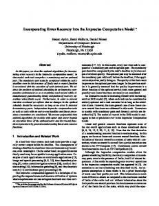
tion of a fail-slow processor. A failure occurs at time tF , and gets detected by the detection mechanism at time tD after a latency period. The operating characteristics of the fail-slow processor are as follows : (i) t < tF : Normal execution. (ii) tF � t < tD : Spurious mode. This is the detection latency period during which the processor may behave arbitrarily. (iii) t � tD : The failure is detected at tD , and all other processors are informed of the failure. Thus, all other processors will detect the failure by time tD + 4.
� Research reported is supported in part by AFOSR under grant F49620-92-J-0383.
1 Realistically, the stable storage only needs to be signi cantly less likely to fail as compared to rest of the system.
tF
tD
X Normal Execution
Detection Latency
Recovery
Figure 1: Operation of a fail-slow processor
The proposed recovery scheme requires that the period between two adjacent checkpoints be larger than the sum of the detection latency � and the worst case message transmission time 4. For simplicity, the proposed recovery scheme is designed to tolerate only a single process failure. During recovery, the system must assess the damage caused by the error. The detection latency of the existent error detection mechanisms can be measured by fault-injection tools (e.g., FERRARI [3], RIFLE [4]). After a failure has occurred, during the detection latency period, a processor may behave arbitrarily. Messages sent by the faulty process during the latency period could be contaminated and thus cause the error to be propagated to other processes. Messages received by the faulty process during the latency period could be corrupted before they are logged. Also, checkpoints taken by the faulty process during the latency period could be corrupted. Thus, the recovery algorithm should undo the damage done by the messages sent, discard the messages received, and discard the checkpoints taken, by the faulty process during the latency period.
3 Terminologies and Data Structures
CPik denotes the k-th checkpoint of process i with k � 0. CPik .time denotes the local time at the stable storage, when k-th checkpoint of process i is received by the stable storage. This timestamp is also saved in the stable storage. Send sequence number (SSN) of a message indicates position of the message in the sequence of outgoing messages. Receive sequence number (RSN) of a message indicates position of the message in the sequence of incoming messages. Sender Log is a log of messages sent by the process, maintained at the stable storage. For each message sent, this includes message data, destination process identi cation, SSN, and local time at the stable storage at which the message is received by the stable storage. Receiver Log contains information about the messages received by the process, and is maintained at the stable storage. For each message received, this includes sender process identi cation, SSN of the message, RSN of the message, and local time at the stable storage at which the message is received by the stable storage. For process i, the jth element of the MaxSSN-Senti vector, Max-SSN-Sentij , denotes the SSN of the most recent message, sent by process i to process j, in the sender log of process i. For process i, the jth element of Max-SSN-Recdi vector, Max-SSNRecdij , denotes the SSN of the most recent message, received by process i from process j, in the receiver log of process i. The Sender Log, Receiver Log, Max-SSN-Sent vector, and Max-SSN-Recd vector must be included in the checkpoint of a process.
4 De nitions
Messages to be logged on stable storage are stored in local bu�ers before they are logged to the stable storage. When the bu�ers get full, the messages are logged by writing these bu�ers to the stable storage. If
any message is present in the bu�er during the detection latency period, the message may be corrupted. A message m is said to \depend on" message m if message m is received by a process before it sends message m. 0
0
De nition 1 Let the local time at the stable storage
at which a message M was logged by process i be tM . � is the time at the stable storage when failure of process i is detected by the stable storage. If (� ?4?�) � tM � � , message m is unsafe, else the message is safe. In addition, a message dependent on an unsafe message is also unsafe.
(� ? 4 ? �) gives the \pessimistic" earliest time (according to the stable storage clock) when the error could have occurred. Therefore, some uncorrupted messages that were logged before the failure actually occurred, may also be declared unsafe. The pessimistic behavior occurs because the stable storage clock is used to determine the unsafe messages. Processor clock cannot be used because it can be faulty when the processor fails (including during the latency period). During recovery, the logs should rst be made safe. This is done in our scheme using a procedure called safe(� , p); � and p are the time of error detection according to the stable storage clock, and the process identi er, respectively. The safe(� , p) nds the unsafe messages (using De nition 1) and deletes them from the logs. Thus, only safe messages are used during the recovery. De nition 2 Let � be the local time at the stable storage when a failure of process i is detected by the stable storage. A checkpoint CP in of process i is unsafe if (� ? 4 ? �) � CPin:time � � , otherwise, the checkpoint is safe.
The recovery algorithm should discard an unsafe checkpoint, as it could be erroneous.
5 Recovery Algorithm
Message logging is performed asynchronously. Each process checkpoints independently with the constraint that time interval between two consecutive checkpoints of a process is at least � + 42 . Upon a failure, recovery is initiated to determine the recovery line to which the processes should rollback. The recovery algorithm rst assesses the damage done by the latency of the detection mechanism. Basing on the knowledge of the time of error detection (according to the stable storage's clock) and � (provided by the system designer3 ), the recovery algorithm determines the earliest time instant when the error could have occurred, and then begins the recovery. 2 This assumption makes sure that at most one checkpoint gets a�ected by an error. 3 If not, � can be de ned to be the maximum latency over all the error detection mechanisms. In those systems where the error detection mechanism can be identi ed, � can be de ned to be the worst case latency of that detection mechanism.
Case I : The simplest case occurs when only a
checkpoint operation takes place during the error latency period, but there are no messages in the local bu�er waiting to be logged on the stable storage. This case is illustrated in Figure 2. � is the time by stable storage's clock at which the stable storage detected failure of process P. Since the transmission delay upper bound is 4, and the error detection latency is �, the earliest instant when the error could have occurred according to the stable storage clock is � ? (4 +�). In
δ+ ∆
C P P1 P L1 m1
m2
m3
X
τ
L2
Time according to Stable Storage clock.
m4
Dotted arrow denotes a data transfer to the Stable Storage.
Q C P Q1
m5 To R
CP P1
Figure 3: Unsafe Messages
CP P2
P L
X Time according to Stable Storage clock.
τ δ +∆
m1
m2
m3
Dotted arrow denotes a data transfer to the Stable Storage.
Q C PQ1
CPQ2
Figure 2: Unsafe Checkpoint this case, as CPP 2 :time > (� ? (� + 4)), the recovery algorithm detects that CPP 2 is an unsafe checkpoint. Therefore, CPP 2 is discarded. As shown in Figure 2, process P logged some messages at time L (i.e. the stable storage received them at L). As L < (� ? (� + 4)), these messages could not have been corrupted by P's failure. Since no messages are logged by P after time L, safe(�, P) does not nd any unsafe messages. Process P rolls back to CPP1 . The sender log and receiver log of process P is used during the recomputation to recover process P's state before the failure. The Max-SSN-Sent vector inferred from the updated sender log is used to avoid the resending of safe messages. Curr SSNi is de ned to be the maximum SSN of the safe messages in the sender log for process i, i.e., Curr SSNi = 8j MAX(Max-SSN-Sentij ). During the recomputation of the checkpoint interval, the resending of messages whose SSN value is less than the Curr SSN is avoided. Messages are received in the same order as indicated by the receiver log. Since the faulty process has not propagated the error to other processes, other processes do not rollback.
Case II : In this case only message transfers take
place during the latency period. This case is illustrated in Figure 3. In this case, as CPP 1:time < (� ? (� + 4)), there are no unsafe checkpoints. We de ne the phrase \logged at time t" as \received by the stable storage at time t". The logging of messages could have taken place sometime before the error had occurred, at time L1, or during the detection latency period at time L2. In both cases, the messages m3 and m4 will be in the local bu�er during the latency period. If logging took place at L2, all the messages sent or received after CPP 1 will be unsafe, because L2 > (� ? (� + 4)). The safe(� , P) operation will remove the entries in the logs corresponding to the unsafe messages, and update the Max-SSN-Sent and
Max-SSN-Recd vectors. On the other hand, if logging took place at time L1, only m3 and m4 will be in the local bu�er. Thus, m3 and m4 are unsafe messages. The safe(� , P) operation will not detect them, as they have not been logged. As explained later, these unsafe messages are detected by requesting the other processes to perform a logging operation upon receipt of the rollback request message from P. Since the destination of the unsafe messages sent by process P may not be correctly stored in the sender log or the local bu�er, process P sends a rollback request message to every other process in the system. MaxSSN-SentPi and Max-SSN-RecdPi , vector elements of P corresponding to a process i are tagged along with the rollback request message to process i. Process i, upon receipt of the rollback request message from P, performs a logging operation, i.e., it logs the messages present in its local bu�er, and updates its Max-SSNSent and Max-SSN-Recd vectors. The Max-SSN-SentPi value is compared with the Max-SSN-RecdiP value of process i. One of the two cases might occur: 1. Max-SSN-RecdiP = Max-SSN-SentPi : This implies that process i did not receive any unsafe messages from process P. Hence, no rollback is necessary. 2. Max-SSN-RecdiP > Max-SSN-SentPi : Inconsistency. Messages have been sent to process i by process P during the detection latency period. This will require process i to rollback to a checkpoint where the value of Max-SSN-RecdiP � Max-SSN-SentPi . The entries in the receiver log of process i corresponding to those messages from P whose SSN values are greater than Max-SSN-SentPi are removed. Process i starts recomputing from a previous checkpoint using the messages in its sender and the receiver log. If process i sends messages to any other process after it had received an unsafe message, those messages will also be unsafe. Process i sends rollback request message to the processes it had sent unsafe messages. Process i then waits for the rollback ack message to arrive from those processes.
For example, in Figure 3, message m5 sent to process R, by process Q, is such an unsafe message, caused due to error propagation. Thus process Q will send a rollback request message to process R. Process Q then waits for the rollback ack message to arrive from process R. Since we assume a reliable network and FIFO channels, the case of Max-SSN-RecdiP < Max-SSN-SentPi will not occur. The value of Max-SSN-RecdPi is compared with the Max-SSN-SentiP value of process i. One of the two cases might occur: 1. Max-SSN-RecdPi = Max-SSN-SentiP : This implies that process P did not receive any messages from process i during the detection latency period. Hence, there is no inconsistency. 2. Max-SSN-RecdPi < Max-SSN-SentiP : Inconsistency. Messages sent by process i have been received by process P during the latency period. This will require the process i to resend those messages whose SSN > Max-SSN-RecdPi . Each process i sends back a rollback ack message back to the failed process P. A noti cation is also sent to process P along with the rollback ack message as to whether process i has to resend the messages that were discarded by process P during the safe(� , P) operation. Upon receipt of rollback ack message from every other process, process P restarts from the previous checkpoint. It resends those messages whose SSN value is greater than Curr SSNP to the respective processes. It requests the processes (which had tagged the noti cation along with the rollback ack message) to resend the messages.
Case III : In this case, both unsafe messages and unsafe checkpoints are present. The recovery scheme
is a combination of the recovery schemes for cases I and II. The details of the algorithm are presented in [8].
6 Simulations
Simulations were performed to evaluate the e�ects of detection latency on recovery. Each process communicates with others by passing messages. The time at which a process sends a message is assumed to follow an exponential distribution with mean of tm . Identity of the destination process is determined randomly (uniformly distributed). The values of the parameters used in the simulation are shown in Table 1. The performance parameters of interest are (i) maximum recovery overhead, (ii) average recovery overhead, (iii) number of processes rolled back due to error propagation and (iv) overhead due to checkpointing and logging. As stated earlier, due to detection latency, error is propagated to processes other than the failed one. Thus, during recovery, more than one process could be rolled back, and, the rollback distance could be more than one checkpoint interval. Recovery overhead for a process is de ned as the period of
Table 1: Simulation Parameters Parameter Message frequency(tm ) Number of processes Checkpoint interval Checkpoint state size Message size Log bu�er size Detection latency (�) Max. Comm. latency (4) Disk transfer rate [5] Disk seek time [6] Disk rotate time [6]
Value(s) chosen 1 message/sec 10 2, 5, 10 minutes 100 Kbytes 2 Kbytes 16, 32 Kbytes 0 (fail-stop) to 1 sec 1 ms 12.5 Mbytes/sec 12.5 ms 13.9 ms
computation lost (rollback distance) due to the failure. Maximum recovery overhead and average recovery overhead are computed as the maximum and average of recovery overheads of all the processes, respectively.
6.1 Results
The detection latency (�) was varied from 0 to 1 sec. Zero detection latency corresponds to a fail-stop processor [7]. Typical latencies are less than 1 sec [3]. The average and maximum recovery overheads were computed for di�erent latency values. Figure 4 demonstrates the average overhead (computed as a percentage of the total runtime), for di�erent checkpoint interval sizes, and for a log size of 16 Kb. As seen, there is an increase in the average recovery overhead as the latency increases. This is because, as the latency increases, the probability of unsafe messages being sent is high. Thus, the number of unsafe processes are higher. By unsafe processes we mean the processes which have received unsafe message(s). Figure 5 shows the number of processes rolled back due to possible error propagation, for di�erent checkpoint interval sizes, and for a log size of 16 Kb. With non-zero latency value, some processes are rolled back due to possible error propagation. Figure 6 demonstrates the maximum overhead (computed as a percentage of the total runtime), for di�erent checkpoint interval sizes, and for a log size of 16 Kb. As seen, the maximum recovery overhead is not much a�ected by the latency value used. The value of latency is typically small to bring about signi cant variation in the maximum recovery overhead. Since the detection latency is small compared to the checkpoint interval, the probability of a checkpoint operation taking place during error detection is small. Therefore, the maximum recovery overhead is relatively independent of latency. Figure 7 shows the failure-free overhead due to checkpointing and logging (computed as a percentage of the total runtime) for di�erent checkpoint interval sizes and for log sizes of 16 Kb and 32 Kb. The overhead depends on the checkpoint size, checkpoint interval size, log size, message size and the I/O bandwidth. The failurefree overhead is quite low for realistic parameter val-
ues.
Ckp. Intl. 2 mins
5 mins
10 mins
16 Kb
4.63%
4.51%
4.49%
32 Kb
2.44%
2.35%
2.3%
Log Size
Percentage Overhead
5 2 mins 5 mins 10 mins
4
3
Figure 7: Checkpointing and Logging overhead
2
1
0 0
0.1 0.2 0.3 0.4 0.5 0.6 0.7 0.8 0.9 Latency in seconds
1
Figure 4: Average overhead
Unsafe Processes
5 2 mins 5 mins 10 mins
4.8
References
4.6
4.4
4.2
4 0
0.1 0.2 0.3 0.4 0.5 0.6 0.7 0.8 0.9 Latency in seconds
1
Figure 5: Unsafe Processes 10 2 mins 5 mins 10 mins
Percentage Overhead
9 8 7 6 5 4 3 2 1 0
0.1 0.2 0.3 0.4 0.5 0.6 0.7 0.8 0.9 Latency in seconds
1
Figure 6: Maximum overhead
7 Conclusions
is comparable with the checkpoint interval, the maximum and average recovery overhead is expected to increase. Thus, a tradeo� exists between the fault coverage and the recovery overhead. Depending on the system requirements the system designer may choose an appropriate value for �. The simulation results show that for typical error detection latencies and checkpoint interval sizes, the proposed scheme provides a higher fault coverage (by allowing non-zero latencies) at almost no additional cost, than schemes that assume zero detection latency.
This paper presents an independent checkpointing and message logging scheme that tolerates error detection latency up to �. The proposed scheme allows the system designer to provide � as an input. Typical error detection latencies are small (less than 1 sec.), therefore � is expected to be small. Larger the chosen value of �, higher is the fault coverage provided by the scheme. For typical values, an increase in � causes only a marginal increase in the average recovery overhead, due to possible error propagation. However, when �
[1] Kai Li, J. F. Naughton and J. S. Plank, \An ef cient checkpointing method for multicomputers with wormhole routing," Intl. Journal of Parallel Programming, Vol. 20, No. 3, pp. 159-180, June, 1992. [2] L. M. Silva and J. G. Silva, \Global checkpointing for distributed programs," IEEE Symp. on Reliable Distributed Systems, pp. 155-162, 1992. [3] G. A. Kanawati, N. A. Kanawati, and J. A. Abraham, \FERRARI: A tool for the validation of system dependability properties,"Proc. 23rd Int'l Symp. on Fault Tolerant Computing, pp. 336-344, June 1992. [4] J. Arlat et. al., \Fault injection for dependability validation: A methodology and some applications," IEEE Transactions on Software Engg., Vol. 16-2, pp. 166-182, Feb. 1990. [5] P. Cao et. al., \The TickerTAIP parallel RAID architecture," Intl. Symp. on Computer Architecture, pp. 52-63, May 1993. [6] D. Stodolsky et. al., \Parity Logging overcoming the small write problem in redundant disk arrays," pp. 64-75, May 1993. [7] R. D. Schlichting and F. B. Schneider, \Fail-stop processors : An approach to designing faulttolerant distributed computing systems," ACM Trans. on Computer Systems, Vol. 1, No. 3, pp. 222-238, Aug. 1983. [8] P. Krishna et. al., \An Optimistic Recovery Scheme for Message-Passing Multicomputer Systems with Finite Detection Latency," Tech. Rept. 94-030, Dept. of Computer Science, Texas A&M University.