IEEE TRANSACTIONS ON COMPUTER-AIDED DESIGN OF INTEGRATED CIRCUITS AND SYSTEMS, VOL. 23, NO. 8, AUGUST 2004
1175
Register Binding-Based RTL Power Management for Control-Flow Intensive Designs Jiong Luo, Lin Zhong, Student Member, IEEE, Yunsi Fei, Student Member, IEEE, and Niraj K. Jha, Fellow, IEEE
Abstract—One important way to reduce power consumption is to reduce the spurious switching activity in a circuit or circuit component, i.e., activity that is not required by its specified functionality. Given a scheduled behavior and functional unit binding, we show that spurious switching activity can be reduced through proper register binding using retentive multiplexers. Retentive multiplexers can preserve their previous select signal values in the control steps in which the select signals are don’t cares. A functional unit, in which spurious switching activity is completely eliminated, is called perfectly power managed. We present a general sufficient condition for register binding to ensure a set of functional units to be perfectly power managed. This condition not only applies to data-flow intensive behaviors, but also to control-flow intensive behaviors. It leads to a straightforward power-managed (PM) register-binding algorithm, which uses this condition to preserve the previous values in the input registers of a functional unit during the states in which the unit is idle. The proposed algorithm is general and independent of the functional unit binding and scheduling algorithms. Hence, it can be easily incorporated into existing high-level synthesis systems. For the benchmarks we experimented with, an average 40.7% power reduction was achieved by our method at the cost of 6.9% average area overhead, compared to power-optimized register-transfer level circuits, which did not use PM register binding. Index Terms—High-level synthesis, low power, power management, register binding.
I. INTRODUCTION
T
HE SIZE and complexity of integrated circuits (ICs) continue to grow as technology scales. The growth of IC complexity is directly reflected in the growth of power consumption and heat dissipation. This creates tremendous new challenges for IC designers. Power optimization can be targeted at different levels of the design hierarchy during the design process. At the logic level, reduction of switched capacitance can be targeted during various synthesis steps, such as technology-independent two-level and multilevel logic optimization, state encoding, retiming, as well as technology mapping [26], [27], [29]. Logic-level power management techniques have also been proposed, such as guarded evaluation [28] and precomputation [12], which try
Manuscript received November 18, 2002; revised July 22, 2003. This work was supported in part by Alternative System Concepts under an SBIR contract from Army CECOM and in part by DARPA under contract no. DAAB07-00-CL516. This paper was recommended by Associate Editor M. F. Jacome. J. Luo was with Department of Electrical Engineering, Princeton University, Princeton NJ 08544 USA. She is now with Synopsys Inc., Mountain View, CA 94043 USA (e-mail:
[email protected]). L. Zhong, Y. Fei, and N. K. Jha are with the Department of Electrical Engineering, Princeton University, Princeton NJ 08544 USA (e-mail:
[email protected];
[email protected]; jha@ee. princeton.edu). Digital Object Identifier 10.1109/TCAD.2004.831597
to reduce or eliminate unnecessary switching activities during idle periods. Guarded evaluation identifies logic blocks that can be shut down under certain input conditions. It uses transparent latches with enable signals to guard the input transitions to those logic blocks. In precomputation, a precomputation logic is added. Specific input conditions are identified under which the original circuit is shut down and the precomputation logic computes the outputs. At the register-transfer level (RTL), load-enabled registers can be used for power management. The register value remains unchanged when its load signal is not enabled. This suppresses the unnecessary transitions in the register output and correspondingly those in the logic block fed by the register output. A more aggressive technique is clock gating, which gates the clock input signal to registers and other circuit clocks. This suppresses the unnecessary transitions in the clock signal, the internal register circuit, and the logic block connected to the register output. However, the benefit of clock gating is restricted by clock skews and register sharing. At the behavior level, power optimization can be targeted during various high-level synthesis steps, including transformation, module selection, scheduling, resource binding, and clock selection, in a comprehensive manner [1]–[11]. Most of these techniques target data-flow intensive (DFI) behaviors, only some target control-flow intensive (CFI) behaviors [6], [11]. High-level synthesis techniques have also been proposed to identify the idle states in a design and synthesize the circuit to eliminate the switching activities during those idle states, in order to power-manage the generated RTL circuit [1], [12]–[18]. One way to eliminate spurious switching activity in functional units is to use transparent latches at the input ports [15]. In the control steps in which the functional unit is idle according to the behavioral specification and its schedule, the latches can prevent propagation of any new value from the registers to functional units. However, the power consumed by the latches themselves reduces the power savings. The latches also incur area overhead due to the addition of extra circuitry. Also, these latches require some delay constraints. One delay constraint is that the disabling signal at the enable input of the transparent latch should arrive before its data input arrives. In order to satisfy the delay constraints, extra circuit delay in the critical path may be incurred that needs to be taken into account. Controller respecification was proposed in [25] as a technique for reconfiguring the multiplexer networks in order to minimize switching activity in idle data-path components. The controller-respecification algorithm consists of identifying conditions under which each data path component need not be
0278-0070/04$20.00 © 2004 IEEE
1176
IEEE TRANSACTIONS ON COMPUTER-AIDED DESIGN OF INTEGRATED CIRCUITS AND SYSTEMS, VOL. 23, NO. 8, AUGUST 2004
active, and respecifing the corresponding control expressions. This technique was extended in [16] for handling CFI designs. However, controller respecification alone cannot completely eliminate spurious switching activity when register sharing is allowed. Moreover, controller respecification may not be efficient for handling CFI designs. It can only reduce the spurious switching activity on the most probable conditional branch, while it cannot reduce the spurious switching activity on other control paths. Register binding not only affects the power consumption in the registers themselves, but may have a significant impact on the power consumption of functional units they feed as well [17], [18]. When a functional unit is going to be idle in the next control step, while its input registers load in new values due to register sharing, spurious switching activity can occur in the functional unit. Improperly binding variables in the behavior to registers can result in significant spurious switching activity in the functional units. A register binding method which guarantees a perfectly power-managed (PPM) RTL circuit if the multiplexer network is properly designed was presented in [17]. It presents a sufficient condition for obtaining PPM RTL circuits for DFI behaviors. This method was extended in [18] to CFI behaviors based on the concept of variable and path protection. The lifetimes of protected variables are extended selectively along protected paths in the schedule in order to ensure that operand values of a functional unit used by the previous operation mapped to it are preserved at its inputs during subsequent idle cycles. Therefore, the spurious switching activity can be eliminated for functional units along the protected path. This paper employs register binding-based power management as well, with a focus on addressing the limitations of previous work when targeting CFI behaviors. Register binding-based power management for CFI behaviors differs from that for DFI behaviors in the following three aspects. First, the overlapping of extended lifetimes of variables needs to be determined by considering the actual runtime-execution paths. Second, different protected paths may require the input select signals of multiplexers to be set to different values. This leads to path conflicts in configuring multiplexer networks. Third, a protected variable may be reassigned a new value along a protected path, which leads to spurious switching activities that cannot be eliminated by register binding alone. The work in [18] proposes to use variable renaming and reassignment to address the third aspect. However, for the first two aspects, it is not adequate or efficient. For the first aspect, it ignores path information when performing lifetime analysis of variables statically and, hence, two variables may be regarded as interfering with each other for register binding, even when their extended lifetimes do not overlap during actual circuit execution. For the second aspect, to resolve path conflicts, it proposes to use extra state memory to remember the previous state, and this state memory is used to configure the multiplexer networks. The number of states to be remembered is determined by the number of conflicting paths. Although extra state memory makes it possible to protect multiple conflicting paths simultaneously, it creates overheads in the controller. Compared to previous works, we make the following contributions.
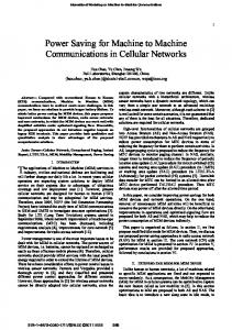
Fig. 1.
Example CFI behavior.
• We present a sufficient condition to ensure that any given set of functional units in an RTL implementation of both DFI and CFI behaviors are PPM. In contrast to the work in [18], this condition is developed based on the analysis of lifetimes of variables in a dynamic manner, by considering actual runtime execution paths. Based on the sufficient condition, we also propose a register-binding algorithm for power-managed (PM) circuits. • We introduce the concept of dynamic retentive multiplexers. Such multiplexers, with minimal extra logic, have the ability to preserve the previous select signal values when the select signals are don’t cares in the controller specification. Compared to controller respecification, this technique can eliminate the spurious switching activity on multiple control paths simultaneously. Moreover, there is no need to remember the state history and add extra logic in the controller to resolve path conflicts while configuring multiplexer networks, as in the approach taken in [18]. As a result, the controller implementation is considerably simplified without sacrificing the ability to protect multiple paths. • To reduce the register overhead, we develop a registerbinding algorithm, which seamlessly combines the sufficient condition for PPM units and the concept of dynamic retentive multiplexers. The proposed algorithm can effectively trade off the power savings and the register overhead introduced. The paper is organized as follows. In Section II, we give an example to motivate our method. In Section III, we present a sufficient condition for PPM register binding which leads to a register-binding algorithm for power management. In Section IV, we present an experimental platform and a technique for incorporating power management checks into existing high-level synthesis tools. We present experimental results in Section V and conclude in Section VI. II. MOTIVATIONAL EXAMPLE In this section, we present an example to motivate our approach. Fig. 1 shows an example behavior. Fig. 2 shows a state transition graph (STG) representing its schedule. , , , , , and are six states besides the start and end states. Inside a state, the operations scheduled in it are shown. The variables needed by each operation are shown close to the state in which
LUO et al.: REGISTER BINDING-BASED RTL POWER MANAGEMENT FOR CFI DESIGNS
1177
input ports 1 and 2 of adder2, respectively, as in state . Moreover, since variable is not defined in state , register 1 still holds the same value in state as in state . Similarly, register 3 still holds the same value since no other variables are bound to it, except variable . Therefore, no spurious switching activity occurs in adder2 in state . It is worth pointing out that, in real designs, spurious switching activity could be much more serious than that in this example if it occurs inside a loop. III. PM REGISTER BINDING
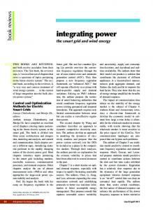
Fig. 2. STG for the behavior.
In this section, we first present some rules to guide register binding in order to reduce the spurious switching activity in a set of functional units in the data path. We then discuss the concept and implementation of retentive multiplexers, which are used to realize PM circuits. We then address the register-binding algorithm. A. Register Binding for PM Circuits
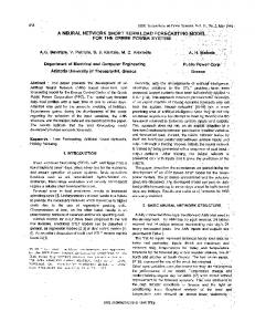
Fig. 3. Part of the RTL implementation.
that operation is scheduled. For example, means takes variables and as inputs. Similarly, that operation means that variable is assigned the value of variable . Suppose the given resource constraints are two adders and and are bound to the comparator. a comparator. and are bound to one of the adders, say adder1, while , and are bound to the other one, say adder2. Now, let us consider how the variables can share registers. Suppose we bind variables and to the same register, and let have its own register, as shown in Fig. 3. In state , the two input values for adder2 correspond to and , respectively. Since variable is defined in state , the register, which is bound to, feeds a new value corresponding to variable in state in which adder2 is supposed to be idle. Assume in state , the select signals for multiplexers MUX2 and MUX3 are all 0. Then, the input values for adder2 correspond to and , respectively. This causes spurious switching activity in adder2 in the transition from state to state . One way to eliminate the possibility of the above spurious switching activity is not to bind variables and to the same register. Instead, we can bind variables and to the same register. We can set the select signals of both MUX2 and MUX3 to 0 in state , such that registers 1 and 3 are still selected to feed
The PM property of a functional unit is jointly ensured through controller specification and register binding. In this section, we dwell on register binding only. As mentioned before, the schedule of a behavior can be represented in the form of an STG. We next provide some definitions required for stating our sufficient condition for a set of functional units to be PPM. is defined as the set of states For each variable , is defined as the set of in which is defined, and states in which is used. A variable is live in state if there is a directed path in the STG from state to another state that uses the variable, without going through any state in except state itself. is defined as the set of states can be generated using liveness in which is live. analysis algorithms from compiler theory [20]. In the example in Section II, we have
For variable , , ; , for variable , ; and for variable , , . Two variables and can share a register if they do not have overlapping lifetimes during circuit execution. This can be determined based on the defstates and livestates of variables and as follows. Theorem 1: Two variables and do not have overlapping lifetimes during circuit execution if , and .
1178
IEEE TRANSACTIONS ON COMPUTER-AIDED DESIGN OF INTEGRATED CIRCUITS AND SYSTEMS, VOL. 23, NO. 8, AUGUST 2004
Fig. 4. Computing extended set of live states of a variable.
Proof: Assume for two variables and , their and do not overlap. During the lifetime of , no and, hence, the value of new value will be loaded into can be maintained during its lifetime, even if and share the same register. Therefore, and do not have overlapping lifetimes during circuit execution. In the example in Section II, if we do not consider spurious and to the switching activity, we can bind variables same register since they satisfy the condition in Theorem 1. However, this condition is not sufficient to avoid spurious switching activity in the circuit. We need to assert some extra conditions to guide register binding, so that during idle states of a functional unit, the input values can be kept the same as those in the previous state. Therefore, no extra switching activity will occur. In order to do this, we introduce the notion of extended set of live states. For a variable , its extended set of live states with respect to functional unit that it feeds is defined and computed recursively by Algorithm is defined as 1 shown in Fig. 4. In this algorithm, the set of states which are the direct successors of state . For each functional unit , is defined as the is idle, as the set set of states in which is used, and as the of states in which , whose direct successors subset of states in all belong to . In the example in Section II, , we have , , and . is initialized In Algorithm 1, is used to feed with the states in which variable , and whose direct successor states functional unit do not all belong to . Any succesare included resors of states in , until any state in cursively into is reached. For the example in Section II, the extended sets of live states for variables and with respect to adder2 are , since in state , variables and are used to feed adder2, and state , the successor of state , belongs to . Similarly, . Theorem 2 below gives a sufficient condition for a set of functional units, , to be PPM. First, we present conditions
that two variables do not interfere with each other during register binding. For any two variables and , assume the set of functional units which feeds is , and the set of functional units . Let , which feeds is . We state that variables and and do not interfere with each other if the following two conditions are satisfied: 1) and and 2) for any , , and for , . any We call these two conditions noninterference conditions. If two variables satisfy the noninterference conditions, we say that they do not interfere with each other. In the example in Section II, assume . Let us look at variables , , and . Variable feeds adder2, and variable feeds adder1. Hence, , and . Theorem 2: During register binding, if the following two conditions are satisfied: 1) any two variables are allowed to share the same register only if they do not interfere with each other and 2) for any variable and any functional unit , , then no spurious switching activity will occur in the functional units in , provided that the multiplexers feeding their input ports are all retentive. Proof: Noninterference condition (a) guarantees that variables and do not have overlapping lifetimes during the running of a circuit if they are bound to the same register. Noninterference condition (b) and the second condition in Theorem 2 guarantee that no extra switching activity occurs . For any functional unit , if the in multiplexers feeding its ports are retentive, then during circuit execution, in any idle state of , the same register will be selected at its input port as in the last state . Furthermore, assume in state , the register holds the value of some variable . Then, should contain state , according to the definitions of extended set of live states. Since any variable which gets defined in state interferes with variable , such an interfering variable will not be bound to this register. Furthermore, if the second condition in Theorem 2 is satisfied, no new value of variable gets defined in state . Hence, no extra switching activity can occur in state . In Theorem 2, condition 1 (noninterference conditions) can be satisfied through proper register binding, while condition 2 is determined by the schedule and cannot be controlled by register binding. However, condition 2 can be satisfied through variable renaming and register reassignment. If condition 2 is not satisfied, we cannot guarantee the PPM property of a set of functional units. However, we can perform register binding based on condition 1 only, which still significantly reduces the spurious switching activity in the circuit, as shown in Section V. We call this PM register binding. According to Theorem 2, variables and in our running example cannot be bound to the same register. Instead, variables and can be bound to the same register even after the live states of variable are extended to include .
LUO et al.: REGISTER BINDING-BASED RTL POWER MANAGEMENT FOR CFI DESIGNS
1179
It is worth noting that in Theorems 1 and 2, the noninterference conditions are based on analyzing the overlap of and , and not on statically analyzing the overlap of lifetimes and extended lifetimes of variables. In this way, two variables are considered interfering with each other if and only if their lifetimes and extended lifetimes overlap during actual execution. It is also worth noting that the lifetime extension and the concept of retentive multiplexers are seamlessly combined together, as suggested in Theorem 2. In this way, the register overhead can be reduced.
compared with placing transparent latches before a functional unit input port [15], the extra hardware for this approach is very small. This is because a transparent latch has the same bit-width as the input port it feeds, whereas we require only a one-bit latch per 2-to-1 multiplexer. The overheads in the controller for the two approaches are similar. In practice, we have found that using static retentive multiplexers eliminates most of the spurious switching activity in a functional unit. The fact that they do not require much overhead makes them doubly attractive.
B. Retentive Multiplexers
C. Register-Binding Algorithm for Power Management
The essence of a PM functional unit is to make sure that it does not have any spurious switching activity, i.e., the input values to it remain the same as they were in the previous state in which it was active. For the input values to remain the same, first, the select signals of the multiplexers feeding its input ports should retain the same values, and second, the register value which feeds the selected input of the multiplexer should remain the same. The latter can be ensured by using the proposed sufficient condition (Theorem 2). However, the former needs help from the controller since retentive multiplexers are assumed. We next provide two different implementations of retentive multiplexers. The first implementation is based on the controller respecification method given in [16]. The don’t cares in the outputs for multiplexer select signals in the state transition table of the controller are identified and assigned proper values. If a multiplexer select signal is a don’t care in state , the corresponding functional unit fed by this multiplexer is idle in state . If the don’t care is replaced with the value assigned to the select signal in the previous state, the multiplexer will output the value from the same input port that it did in the previous state. A problem arises when a state has multiple predecessor states. In this case, with this method, it becomes impossible to guarantee elimination of all spurious switching activity in the functional unit. Then, the preceding state with the highest transition probability into the current state is identified and the don’t care is replaced with the value in that state. The spurious switching activity can be statistically reduced in this case. Such a multiplexer is called static retentive since the don’t cares are assigned values statically. In the second implementation, we can introduce a small amount of extra hardware to make the multiplexer completely retentive. An extra control signal can be added to indicate whether the functional unit under consideration is idle or not. It is assigned a 0 in the states in which the functional unit is idle. Select signals to a functional unit’s multiplexers are don’t care in a state if and only if the functional unit is idle in that state. A one-bit delay latch [19] can be added to the select signal input of the multiplexer. When the functional unit is idle, the latch is disabled and it holds the previous value. In this way, the multiplexer remembers the select signal value of the last state the functional unit was in. The extra bit acts as the enable signal for the latch. We call such multiplexers dynamic retentive. These are the multiplexers assumed in Theorem 2. The disadvantage of such a design is the overhead introduced in the controller (one extra bit per functional unit) and multiplexers (one-bit latch per 2-to-1 multibit functional unit multiplexer). However,
PM register binding tries to reduce spurious switching activity in functional units with the help of some extra registers needed for this purpose. This causes some area and power overhead in registers. The power/area of some register implementations can be comparable to those of some functional units. For example, we found that an eight-bit register on an average consumes more power than an eight-bit ripple-carry adder if implemented in NEC CB-11 0.18- m cell-based technology [21]. Therefore, in order to make an adder PM, if we have to introduce an extra register, the tradeoff is not worth it. Therefore, we need to balance register power consumption overhead and spurious switching activity in functional units. In order to trade off the register power-consumption overhead and power savings in functional units, we present the register-binding algorithm as Algorithm 2 in Fig. 5. In this algorithm, the list of candidate functional units can be initialized as all the functional units in the circuit, or as a subset of the functional units we want to target. The register constraint is the user-specified maximum number of registers in the system. The interference graph is constructed based on noninterference conditions defined in Section III-A. When two variables interfere with each other, an edge is added between them in the interference graph. IV. EXPERIMENTAL PLATFORM To evaluate the proposed method, we incorporated it into an existing low-power high-level synthesis tool that is an extended version of the one described in [10] and can handle both DFI and CFI behaviors. The main modification we needed to make to the synthesis flow was that instead of interleaving functional unit binding with register binding, we first performed functional unit binding and then register binding. This ensures that for different register binding methods, the same functional unit optimization is done. Fig. 6 shows a high-level view of the tool. After reading the specification in the form of a CDFG and resource or timing constraints, it starts with either time-constrained scheduling (for DFI behaviors) or resource-constrained scheduling (for CFI behaviors). The resulting STG is simulated to collect data to evaluate the power and timing of the RTL architectures generated later. Data path optimization is based on variable-depth iterative improvement which is capable of escaping local minima. It starts with a fully parallel architecture in which each operation is bound to its own fastest possible functional unit from the RTL design library and each variable is bound to its own register. This architecture is iteratively improved for power optimization
1180
IEEE TRANSACTIONS ON COMPUTER-AIDED DESIGN OF INTEGRATED CIRCUITS AND SYSTEMS, VOL. 23, NO. 8, AUGUST 2004
Fig. 5. PM register binding.
TABLE I POWER AND AREA FOR CIRCUITS WITH MAXIMAL REGISTER BINDING
done as described in Section III-B. That is, static retentive multiplexers are used for different register bindings, and don’t cares in the controller state transition table are appropriately specified. Our register-binding technique can be incorporated in other high-level synthesis tools as well. Once scheduling and functional unit binding information is available, register binding can simply be based on the sufficient condition given in Theorem 2. Fig. 6.
High-level view of the tool.
purposes through various moves such as functional unit selection, resource sharing/splitting, multiplexer tree synthesis, etc., first for functional units and then for registers. If a PM circuit is desired, condition 1 in Theorem 2 is checked before two variables are allowed to share a register. The power-optimized RTL data path is output at the end. This is the best architecture seen during iterative improvement. Then, controller respecification is
V. EXPERIMENTAL RESULTS In this section, we present experimental results for our proposed techniques. Two register binding methods are compared. The first (maximal) allows as much sharing of registers as possible without regard to spurious switching activity. The second is register binding to obtain a PM circuit using Theorem 2. The controller is respecified as described in Section III-B in both
LUO et al.: REGISTER BINDING-BASED RTL POWER MANAGEMENT FOR CFI DESIGNS
1181
TABLE II MAXIMAL VERSUS PM REGISTER BINDING
Fig. 7.
Total power consumption for different techniques.
the cases. We show results for both static and dynamic retentive multiplexers. We used various high-level synthesis benchmarks to establish the efficacy of our technique. chemical is an infinite impulse response (IIR) filter used in the industry. dct_dif, dct_lee,, and dct_wang are different algorithms for computing discrete cosine transform [22]. diffeq is a differential equation solver from the NCSU CBL high-level synthesis benchmark repository [23]. paulin is a variant of diffeq from [24]. wavelet performs the discrete wavelet transform. fft performs the fast Fourier transform algorithm. They have been widely used by the research community. con_loop, while_loop, if_in_loop, and for_loop are synthetic CFI examples to test different control flow constructs.
The power consumption and area of the RTL circuits are computed using an NEC RTL library for the 0.35- m technology. The benchmarks used in this paper can be downloaded from [30]. Table I shows total power and area of the controller/data path implementations of the different behaviors for the maximal register binding case. In Table II, we show the percentage reduction in total power as well as the overhead in area for PM circuits (i.e., all functional units are PM) compared to the maximal register binding case. We also show the number of registers for the two cases. On average, the PM circuits reduce total power by 40.7% at an area overhead of 6.9%, compared to circuits which are power-optimized except that they ignore spurious switching
1182
Fig. 8.
IEEE TRANSACTIONS ON COMPUTER-AIDED DESIGN OF INTEGRATED CIRCUITS AND SYSTEMS, VOL. 23, NO. 8, AUGUST 2004
Spurious switching activity percentage for different register bindings.
activity. In terms of CPU time, the overall synthesis finishes within seconds for all the examples, on a Pentium-III 933 MHz machine with 256 MB of memory. The total power for the three cases, maximal, PM with static retentive multiplexers, and PM with dynamic retentive multiplexers, is plotted in Fig. 7. Dynamic retentive multiplexers do help in seven cases, but not in others. Fig. 8 shows the percentage of the total functional unit switching activity that is spurious for two different register bindings. One can see that PM units reduce the spurious switching activity significantly. If dynamic retentive multiplexers are employed, there will be no spurious switching activity at all. From our experimental results, it can be observed that spurious switching activity may account for a large portion of total power consumption. Hence, our techniques are quite effective in reducing power consumption. For example, in dct_wang, the total number of registers increases from 20 to 30. However, since the area of registers is small compared to the functional units, we do not observe much area overhead. In the original register-binding algorithm, maximal register sharing is done to optimize area. This does not take into account the spurious switching activity. Hence, functional units have spurious switching activities in most of the idle states. Since, for this example, idle states contribute to a large fraction of the total number of states, we observe a significant power reduction, since most of the spurious switching activity is eliminated by applying our algorithm. Our approach is also superior to approaches based on transparent latches [15]. As discussed before, approaches based on transparent latches have some fundamental disadvantages. They can incur power and area overheads. Moreover, in order for the power management to take effect, the enable signal to the transparent latches have to arrive before the data inputs can change. However, the signals that detect idle conditions may depend on outputs of comparators from the data path, and therefore can be late-arriving. As a result, the timing constraints to guarantee successful power management may not be met for high-performance circuit designs. Also, for most of our examples, the register overhead is very small (an average of only 18.2%), com-
pared to the overhead of inserting latches on both input ports of all the functional units. The proposed algorithm actually can intelligently guide register allocation to avoid spurious switching activity, without incurring much register overhead. Moreover, the register overhead can be restricted based on Algorithm 2. VI. CONCLUSION We have demonstrated that by properly binding variables to registers in high-level synthesis, spurious switching activity in functional units can be significantly reduced. We gave a general sufficient condition for a set of functional units to be free of spurious switching activity in implementations of both DFI and CFI behaviors. Based on this condition, we proposed a register-binding algorithm to reduce spurious switching activity in a given set of functional units. We achieved an average 40.7% power reduction at an average 6.9% area overhead compared to already power-optimized architectures. We also discussed how the controller and/or multiplexers can be redesigned to cooperate with register binding to reduce spurious switching activity in the data path. Dynamic retentive multiplexers can eliminate most spurious switching activity but introduce some extra hardware which is very small compared to that of placing transparent latches before functional units’ input ports. REFERENCES [1] A. Raghunathan, N. K. Jha, and S. Dey, High-Level Power Analysis and Optimization. Norwell, MA: Kluwer, 1998. [2] R. Mehra and J. Rabaey, “Behavioral level power estimation and exploration,” in Proc. Int. Workshop Low-Power Design, Jan. 1994, pp. 255–270. [3] L. Goodby, A. Orailoglu, and P. M. Chau, “Microarchitecture synthesis of performance-constrained, low power VLSI designs,” in Proc. Int. Conf. Comput. Design, Oct. 1994, pp. 323–326. [4] A. Dasgupta and R. Karri, “Simultaneous scheduling and binding for power minimization during microarchitecture synthesis,” in Proc. Int. Symp. Low-Power Design, Apr. 1995, pp. 69–74. [5] J. M. Chang and M. Pedram, “Register allocation and binding for low power,” in Proc. Design Automation Conf., June 1995, pp. 29–35. [6] N. Kumar, S. Katkoori, L. Rader, and R. Vemuri, “Profile-driven behavioral synthesis for low-power VLSI systems,” IEEE Design Test Comput., vol. 12, pp. 70–84, Sept. 1995.
LUO et al.: REGISTER BINDING-BASED RTL POWER MANAGEMENT FOR CFI DESIGNS
[7] A. P. Chandrakasan, M. Potkonjak, R. Mehra, J. Rabaey, and R. Brodersen, “Optimizing power using transformations,” IEEE Trans. Computer-Aided Design, vol. 14, pp. 12–51, Jan. 1995. [8] R. S. Martin and J. P. Knight, “Power profiler: Optimizing ASIC’s power consumption at the behavioral level,” in Proc. Design Automation Conf., June 1995, pp. 42–47. [9] M. Johnson and K. Roy, “Optimal selection of supply voltages and level conversions during data path scheduling under resource constraints,” in Proc. Int. Conf. Comput. Design, Oct. 1996, pp. 72–77. [10] A. Raghunathan and N. K. Jha, “SCALP: An iterative improvement based low-power data path synthesis algorithm,” IEEE Trans. Computer-Aided Design, vol. 16, pp. 1260–1277, Nov. 1997. [11] K. S. Khouri, G. Lakshminarayana, and N. K. Jha, “High-level synthesis of low power control-flow intensive circuits,” IEEE Trans. ComputerAided Design, vol. 18, pp. 1715–1725, Dec. 1999. [12] M. Alidina, J. Monteiro, S. Devadas, A. Ghosh, and M. Papaefthymiou, “Precomputation-based sequential logic optimization for low power,” IEEE Trans. VLSI Syst., vol. 2, pp. 426–436, Dec. 1994. [13] J. Monteiro, P. Ashar, and S. Devadas, “Scheduling techniques to enable power management,” in Proc. Design Automation Conf., June 1996, pp. 349–352. [14] C. Papachristou, M. Spining, and M. Nourani, “An effective power management scheme for RTL design based on multiple clocks,” in Proc. Design Automation Conf., June 1996, pp. 337–342. [15] E. Mussoll and J. Cortadella, “High-level synthesis techniques for reducing the activity of functional unit,” in Proc. Int. Symp. Low-Power Design, Apr. 1995, pp. 99–104. [16] S. Dey, A. Raghunathan, N. K. Jha, and K. Wakabayashi, “Controller-based power management for control-flow intensive designs,” IEEE Trans. Computer-Aided Design, vol. 18, pp. 1496–1508, Oct. 1999. [17] G. Lakshminarayana, A. Raghunanthan, N. K. Jha, and S. Dey, “Power management in high level synthesis,” IEEE Trans. VLSI Syst., vol. 7, pp. 7–15, Mar. 1999. , “Transforming control-flow intensive designs to facilitate power [18] management,” in Proc. Int. Conf. Computer-Aided Design, Nov. 1998, pp. 657–664. [19] V. P. Nelson, H. T. Nagle, B. D. Carroll, and J. D. Irwin, Digital Logic Circuit Analysis and Design. Englewood Cliffs, NJ: Prentice-Hall, 1995. [20] A. W. Appel, Modern Compiler Implementation in ML. New York: Cambridge Univ. Press, 1998. [21] NEC CB-11 Technology [Online]. Available: http://www.necel.com/ asic/cell-based.cfm [22] K. R. Rao and P. Yip, Discrete Cosine Transform. Reading, MA: Academic, 1990. [23] NCSU High-Level Synthesis Benchmarks [Online]. Available: http://www.cbl.ncsu.edu/benchmarks/ [24] P. G. Paulin and J. P. Knight, “Force-directed scheduling for the behavioral synthesis of ASICs,” IEEE Trans. Computer-Aided Design, vol. 8, pp. 661–679, June 1989. [25] A. Raghunathan, S. Dey, and N. K. Jha, “Controller re-specification to minimize switching activity in controller/datapath circuits,” in Proc. Int. Symp. Low-Power Electron. Design, Aug. 1996, pp. 301–304. [26] S. Devadas and S. Malik, “A survey of optimization techniques targeting low power VLSI circuits,” in Proc. Design Automation Conf., June 1995, pp. 242–247. [27] J. Monteiro and S. Devadas, Computer-Aided Design Techniques for Low Power Sequential Logic Circuits. Norwell, MA: Kluwer, 1996. [28] V. Tiwari, S. Malik, and P. Ashar, “Guarded evaluation: Pushing power management to logic synthesis/design,” IEEE Trans. Computer-Aided Design, vol. 17, pp. 1051–1060, Oct. 1998. [29] V. Tiwari, P. Ashar, and S. Malik, “Technology mapping for low power,” in Proc. Design Automation Conf., June 1993, pp. 74–79. [30] High-Level Synthesis Benchmarks [Online]. Available: http://www.princeton.edu/~lzhong/publications/zhong02iccdbenchmarks.tar.gz
1183
Jiong Luo received the B.E. degree in electrical engineering from Tsinghua University, Beijing, China, in 1993 and the M.A. and Ph.D. degrees in electrical engineering from Princeton University, Princeton, NJ, in 2000 and 2003, respectively. She is now with Synopsys Inc., Mountain View, CA. Her research interests include computer-aided design of integrated circuits and systems and lowpower design of electronic circuits.
Lin Zhong (S’02) received the B.S. and M.S. degrees in electronic engineering from Tsinghua University, Beijing, China, in 1998 and 2000, respectively. He is currently pursuing the Ph.D. degree at Princeton University, Princeton, NJ. His research interests include energy efficiency and user interface for mobile computing systems, architecture and computer-aided design for circuits using nanometer devices, and high-level synthesis.
Yunsi Fei (S’01) received the B.Eng. and M.Eng. degrees in electronic engineering from Tsinghua University, Beijing, China, in 1997 and 1999, respectively, and the M.A. degree in electrical engineering in 2001 from Princeton University, Princeton, NJ, where she is currently pursuing the Ph.D. degree in electrical engineering. Her interests include system-level cosynthesis, high-level synthesis, power analysis and synthesis of application-specific instruction set processor, embedded-software and operating-system design for low power, and power management for portable devices.
Niraj K. Jha (S’85–M’85–SM’93–F’98) received the B.Tech. degree in electronics and electrical communication engineering from the Indian Institute of Technology, Kharagpur, India in 1981, the M.S. degree in electrical engineering from the State University of New York, Stony Brook, in 1982, and the Ph.D. degree in electrical engineering from the University of Illinois, Urbana, in 1985. He is a Professor of Electrical Engineering at Princeton University, Princeton, NJ. He has coauthored three books, entitled Testing and Reliable Design of CMOS Circuits (Norwell, MA: Kluwer, 1990), High-Level Power Analysis and Optimization (Norwell, MA: Kluwer, 1998), and Testing of Digital Systems (Cambridge, U.K.: Cambridge University Press, 2003). He has authored or coauthored more than 230 technical papers. He holds 11 U.S. patents. His research interests include low-power hardware and software design, computer-aided design of integrated circuits and systems, digital system testing, and distributed computing. Prof. Jha is a Fellow of the ACM. He has served as an Associate Editor of the IEEE TRANSACTIONS ON CIRCUITS AND SYSTEMS II: ANALOG AND DIGITAL SIGNAL PROCESSING. He is currently serving as an Editor of the IEEE TRANSACTIONS ON COMPUTER-AIDED DESIGN OF INTEGRATED CIRCUITS AND SYSTEMS, the IEEE TRANSACTIONS ON VLSI SYSTEMS, the Journal of Electronic Testing: Theory and Applications (JETTA), and the Journal of Embedded Computing. He has served as the Guest Editor for the JETTA special issue on High-Level Test Synthesis. He has also served as the Program Chairman of the 1992 Workshop on Fault-Tolerant Parallel and Distributed Systems. He is the recipient of the AT&T Foundation Award, the NEC Preceptorship Award for research excellence, and NCR Award for Teaching Excellence. He coauthored six papers which have won the Best Paper Award at ICCD’93, FTCS’97, ICVLSID’98, DAC’99, PDCS’02, and ICVLSID’03.