AbstractâIn Programming by Demonstration, a flexible representation of manipulation motions is necessary to learn ...... IOS Press, 2006, pp. 856â864.
Representation and constrained planning of manipulation strategies in the context of Programming by Demonstration Rainer J¨akel1) , Sven R. Schmidt-Rohr1) , Martin L¨osch1) , R¨udiger Dillmann1) Abstract— In Programming by Demonstration, a flexible representation of manipulation motions is necessary to learn and generalize from human demonstrations. In contrast to subsymbolic representations of trajectories, e.g. based on a Gaussian Mixture Model, a partially symbolic representation of manipulation strategies based on a temporal satisfaction problem with domain constraints is developed. By using constrained motion planning and a geometric constraint representation, generalization to different robot systems and new environments is achieved. In order to plan learned manipulation strategies the RRT-based algorithm by Stilman et al. is extended to consider, that multiple sets of constraints are possible during the extension of the search tree.
using the PbD paradigm, see section VI, and generalized to different robots, objects and environments on a symbolic level. Recent advances in the field of constraint motion planning are incorporated to plan robot trajectories based on a given manipulation strategy, which will be discussed in section VII. In section VIII, experiments on two different robot systems are reported. The first robot system consists of two Kuka lightweight arms with seven degrees of freedom (DOF) and two Schunk anthropomorphic robot hands with four fingers and 13 DOFs. The second robot system is made up by a six DOF robot arm, a force sensor in the wrist and a Barrett hand with three fingers and four DOFs.
I. INTRODUCTION In service robotics, anthropomorphic robot systems are being developed, that should be able to assist humans in their natural environment. Typical household or cafeteria tasks are complex, i.e. the robot system has to detect and grasp arbitrary objects, move these objects on collision free paths, perform complex motions with the objects and apply force to specific areas in a controlled way. Due to this complexity, the fundamental problem of how to represent and learn manipulation strategies arises. In recent years, symbolic representations on the basis of atomic, predefined operators had great success, because they allow for the hierarchical, comprehensible representation of manipulation knowledge, the flexible adaption to different environments and the combination of atomic operators with different inner representations. In Programming by Demonstration (PbD), the demonstration of a human operator forms the basis for the learning, i.e. parameterization, of atomic operators and the learning of complex task structures. In this approach, generalization and adaption to different environments heavily depends on the representation of the atomic operators. Purely subsymbolic representations, e.g. based on learned trajectories or controller parameters, are hard to generalize to different robots and environments. In this work, a (partially) symbolic representation of manipulation strategies is developed, that explicitly describes the search space for trajectories consistent with the strategy by a complex, temporal network of robot constraints, see section IV. Based on the structure of constraints, manipulation strategies can be efficiently learned This work has been partially conducted within the german SFB 588 “Humanoid Robots” granted by DFG and within the ECs Integrated Project DEXMART under grant agreement no. 126239 (FP7/2007-2013) . 1) Institute of Anthropomatics, Karlsruhe Institute of Technology, 76131 Karlsruhe, Germany
II. RELATED WORK Up to now, no standard representation of task knowledge or manipulation strategies has become apparent in service robotics. Tree-like representations, e.g. HTN [1] or TDL [2], and procedural languages [3] have an advantage over classical robot programming languages due to the high reusability, suitability for learning and interpretability of hierarchical knowledge. For example, Flexible Programs (FP) [4] are a symbolic, hierarchical, HTN-like representation of task knowledge. Similar to this work, runtime conditions can be assigned to nodes, but it hasn’t been worked out, how these conditions can be considered in the planning of manipulation strategies. In [9], a representation of goal regions for constrained motion planning based on 6d hypercubes in cartesian space was developed, that forms a specific instance of the representation developed in this work. In order to represent sequentiality and parallelism of events, which is fundamental to the definition of manipulation strategies, a formal representation of time has to be introduced. Temporal constraint satisfaction problems, which describe the temporal relationship between pairs of temporal variables, have been investigated by Dechter et al [5]. In recent years, disjunctive temporal constraints have been proposed as a general framework for planning with temporal constraints [6]. In the referenced work, partial order planning (POP) is used as a basis to plan the execution of STRIPS-like operators, i.e. with pre- and post conditions, assuming disjunctive temporal constraints between the start- and end times of actions. Due to the different search spaces of POP and motion planners, a different approach of planning under temporal constraints will be investigated. The planning of manipulation motions for robot systems
with many DOFs is highly demanding. Building on recent advances in the field of constrained motion planning using TC-RRTs [7], [8] constraints can be considered in the planning process, which is fundamental for the results presented in this work. In [8], the extend function of the standard RRT is replaced by a constrained extend method, which projects a small step into a sampled direction onto the constraint manifold around a given node. In order to calculate this projection, the set of constraints has to be explicitly defined. In the context of manipulation strategies, the temporal ordering of events, and therefore the set of constraints valid at a given time point, is not known prior to the planning process. In this work, the TC-RRT is extended to incorporate temporal and domain constraints. III. TEMPORAL CONSTRAINT SATISFACTION PROBLEMS In this section, we give a brief introduction to temporal constraint satisfaction problems (TCSP) [5], which form the basis of the developed representation of manipulation motions. In addition to temporal constraints, general constraints on the robot motion are considered the atomic elements of manipulation motions. By extending the definition to include domain constraints and disjunctions of temporal constraints, the TDCSP will be defined. A. Definition A TCSP is a tuple (X, Ctg , Ctr ) with the set of variables X = {xi ∈ [0, ∞)|i = 1, ..., n}, the set of global constraints Ctg = {(x, l, u)|x ∈ X, [l, u] 6= ∅} and the set of relative constraints Ctr = {(x, y, l, u)|x, y ∈ X, [l, u] 6= ∅}. The variables describe specific time points, in this case, on a trajectory. The possible values of each variable are restricted by global constraints, which are defined as intervals on R≥0 . Relative constraints restrict the time difference between two variables. An assignment (t1 , ..., tn ) ∈ Rn≥0 of the variables (x1 , ..., xn ) is consistent with the TCSP, if
describes the configuration of the robot at time t. The set of constraint evaluation functions is extended by ^ φ(θ(ti )) Cgd (i) := {φ| ∃(i, φ) ∈ Cdg } φ∈Cgd (i)
^
^
φ(θ(t))
Crd (i, j) := {φ| ∃(i, j, φ) ∈ Cdr }
φ∈Crd (i,j) t∈[ti ,tj ]
with the domain constraints Cgd (i) of variable xi and the domain constraints Crd (i, j) between xi and xj . B. Arc consistency checking and AC-3 Consistency checking, which is NP-hard [5], can be solved by searching for a valid assignment of the variables. Most global search algorithms incrementally test assignments of the variables using (weak) consistency requirements to prune the domains of unassigned variables. Arc consistency [10] is a consistency condition, that forces the domains of two variables to be consistent, i.e. for each value in the domain of one variable a consistent value in the domain of the second variable has to exist and vice versa. Arc consistency can be maintained by a simple algorithm called AC-3 [10], which iteratively calls the function Remove-Inconsistent-Values(i,j) to prune the domain values of the variable xi , that are inconsistent with domain values of the variable xj . For tree like TCSPs, arc consistency is equivalent to consistency [10]. IV. REPRESENTATION OF MANIPULATION MOTIONS AND STRATEGIES In this section, we motivate and discuss our representation of manipulation motions and strategies, which is based on a TDCSP enhanced by conditional arcs. A. Motivation
A manipulation motion is defined as an unconditioned motion of the robot system. The most common representation is a trajectory in the configuration space C of the robot, that can be learned by playback programming and directly executed on the robot system. In general, genti ∈ [l, u] ∀(i, l, u) ∈ Ctg eralization to different domains, e.g. with different start, t tj − ti ∈ [l, u] ∀(i, j, l, u) ∈ Cr target and object positions is not possible. In order to In order to describe real world problems, disjunctions of improve generalization, allowed variations of the trajectories temporal constraints have to be considered in the TCSP for- can be learned based on multiple demonstrations. In [11], Gaussian mixture regression is used to determine a more mulation by modifying the constraint evaluation equations: _ flexible trajectory representation based on Gaussians. The ti ∈ [l, u] Cgt (i) := {(l, u)| ∃(i, l, u) ∈ Ctg } main advantages of purely subsymbolic representations are (l,u) fast learning times and low effort for the transformation to t (i) ∈Cg the robot system. Generalization to new objects and envi_ tj − ti ∈ [l, u] Crt (i, j) := {(l, u)| ∃(i, j, l, u) ∈ Ctr } ronments is complicated, due to the lack of understanding (l,u) of what the goals are and why the solution is structured in t (i,j) ∈Cr a specific way. On the other hand, background knowledge In this work, a TCSP with domain constraints (TDCSP) is can be easily integrated into a symbolic, e.g. STRIPSdefined as a tuple (X, Ctg , Ctr , Cdg , Cdr , θ), with X, Ctg and like, representation. The symbolic description allows for the Ctr as before. The set of global domain constraints on the generalization based on symbolic properties, leading to a variables is Cdg = {(x, φ)|x ∈ X, φ : C → {0, 1}}, where C high degree of reusability, i.e. actions can be applied to will be the configuration space of the robot and φ describes objects with equal properties. Due to the complexity of robot a binary constraint. The set of relative domain constraints is manipulation, purely symbolic descriptions are insufficient defined as Cdr = {(x, y, φ)|x, y ∈ X, φ : C → {0, 1}}. θ(t) to represent manipulation motions as an input for motion
planning techniques. Consider the pour-in task, which could be described by the target relation isFilled (Glass, Water ) and runtime constraint !isWet(Table). This simple symbolic description demands a powerful planning system taking the water dynamics into account. By mapping the relation !isWet(Table) to a subsymbolic constraint, that restricts the orientation of the bottle to be ”upright”, the problem complexity can be heavily reduced. Based on this observation, a representation capturing symbolic and subsymbolic properties of manipulation motions has been developed. In general, manipulation motions are heavily constrained, e.g. pushing a button requires the robot to stay in contact with a small part of an object. Instead of viewing constraints as a way to restrict motions, we regard constraints as the atomic element of manipulation motions and strategies, which can be combined in sequence and in parallel to describe the space of trajectories consistent with the manipulation motion. By introducing object depended constraints, e.g. staying on the table top, we derive a representation, that can be easily transformed to new environments based on its symbolic properties and easily executed based on the subsymbolic information provided by domain constraints. B. Formal definition In the previous subsection, the use of constraints as the atomic element of manipulation motions and strategies has been motivated. Manipulation motions are described as a network of parallel and sequential constraints, which results in a TDCSP (X, Ctg , Ctr , Cdg , Cdr , θ), where x1 is the start node and xn is the target node. The set Cdg (i) describes the constraints on the node xi , that have to be valid in a specific time point on the trajectory θ. The set of constraints, that have to be valid for all points on θ between the time points xi and xj is described by Cdr (i, j). In this work, a domain constraint is defined as a tuple (o, R) with ˙ t) ∈ R(θ, θ, ˙ t), o(θ, θ,
(1)
where o is a function depending on θ, θ˙ and t with values in a subset R of the space S. o is called constrained object, because it will represent a symbolic property of an object, e.g. the tip of a finger or the opening of a bottle. R is called constrained region, because it restricts the possible values of a constrained object. A symbolic example of a constrained region is the top of a table represented by a cubic region. In the context of bimanual manipulation, this representation of constraints has been proven useful for learning, generalization and planning of manipulation motions and strategies. The extension to higher derivatives is straight forward. Based on this constraint representation, the set of domain constraints Cdr is defined as Cdr
={
(xi , xj , (o, R))|xi , xj ∈ X, 2
o : C × [0, ∞] → S, S Space, R : C2 × [0, ∞] → P(S) } The set of node domain constraints Cdg is defined analogously. The constraints Cdg (n) of the target node are
TABLE I R EGION TYPES , PARAMETERS AND SPACES Icon
Parameters π r0 , r1 ∈ R≥0 , r1 > r0 ri ∈ R≥0 , i = 1, ..., n α0 , α1 ∈ [0, 2π], α1 > α0 , h ∈ R≥0 r0 , r1 , h ∈ R≥0 , r1 > r0
Type Sphere Cube Cone Cylinder
Space Rn , n ≥ 2 Rn , n ≥ 1 Rn , n ≥ 2 Rn , n ≥ 3
{b11, ...}
S
1
[l2, u2], {c21, ...}
[l4 ,
[l3, u3], {c31, ...}
u4 ]
, {c
41 ,
...}
[l1, u1], {strategy11(x1, ...), ..., c11, ...}
E
{b11, ...}
S
1
[l2, u2], {c21, ...}
[0,0]
[l4 ,
[l3, u3], {c31, ...}
S
, {c
41 ,
E [l1, u1], {c11, ...}
u4 ]
...}
E [0,0]
strategy11
Fig. 1. Strategy graph for a manipulation strategy with conditional arc and hierarchical reuse of a manipulation strategy (bottom)
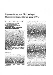
the goal of the manipulation motion. Preconditions are equivalent to the constraints Cdg (1) of the start node. In the example strategies, .r describes the position of an object, .q the orientation and .θ a part of the robot configuration. In the learning process, constrained regions are restricted to cones cylinders, spheres and cubes, see table I. Cones and cylinders are aligned to the z-axis. C. Strategy graph Manipulation motions can be visualized as a directed graph, called strategy graph, which is shown in fig. 1. Each node (xi , Cgt (i), Cgd (i)) describes a variable xi with the temporal constraints Cgt (i) and a set of domain constraints Cgd (i). Arcs (xi , xj , Cgt (i, j), Cgd (i, j)) describe relative constraints between two variables xi and xj . In this work, temporal constraints are described by a single interval [li , ui ]. The start and end node are highlighted as xs and xt . Conditional arcs (xi , xj , Ccd (i, j), α), which will be explained in the next subsection, are grey. Ccd (i, j), is a set of domain constraints. The small number in the root of a conditional arc describes its priority α. D. Manipulation strategies Atomic constraints have been motivated as a basis for a more flexible, symbolic and subsymbolic representation of trajectories, suitable for learning, generalization and planning. The developed representation of manipulation motions doesn’t include conditional branching or hierarchical structuring. From this point of view, manipulation motions
{H1.r ∈ (1,1,1), G1.Θ ∈ (0)} S
[0,∞] {}
X
[10,20] {H1.r ∈ (0,1,6), G1.Θ ∈ (0)}
{H1.r ∈ (1,1,1), G1.Θ ∈ (0)}
{Cup.q ∈ (0,5,1), distance(Cup.r) ∈ (300,∞)}
2
S
1
{H1.force ∈
1
: relative to start pose above object, z points down : relative to pose at time of node X : pose at time of node X + (0,0,5)
Fig. 2.
{H1.graspquality ∈
(0, 0.1)}
[0,∞] {H2.Θ ∈ (0), Bottle.q ∈ (0,80,1)}
[0,∞] {H1.Θ ∈ (0)}
[0,∞] {Grasp}
(0, 0, 1)}
{Bottle.q ∈ (75,80,1), Bottle.r ∈ (0,20,50)}
2
[0,∞] {H2.Θ ∈ (0), Bottle.q ∈ (75,155,1), Bottle.r ∈ (0,5)}
E
{Bottle.q ∈ (145,155,1), Bottle.r ∈ (0,20,50)}
Example: Grasping of an object using force values
[0,∞] {H2.Θ ∈ (0), Bottle.q ∈ (0,155,1), Bottle.r ∈ (0,5)}
{Bottle.q ∈ (0,80,1), Bottle.r ∈ (0,20,50)}
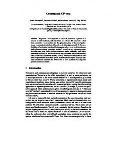
subsume atomic action representations in classical symbolic representations, like elementary operators in FPs. In order to improve reusability of knowledge and to support closed sensor-actor loops, hierarchical structuring and conditional branching have to be incorporated. Manipulation motions can be hierarchically structured by replacing a simple constraint with a manipulation motion. Time constraints and domain constraints are transformed to constraints between the start and end node, as displayed in fig. 1. Additionally, this allows for the incorporation of arbitrary manipulation knowledge, e.g. classical atomic actions with pre and post conditions. Conditional branching is explicitly modeled as a conditional arc (CA). In contrast to normal edges, a CA is instantanious, has no temporal or domain constraints and describes a branch in the execution. Each conditional arc has a condition, i.e. a set of domain constraints Ccd (i, j) and a priority α, assigned to it. When the execution stops in a node with CAs, the condition of each CA and the set of node constraints of the target node of the chosen CA is evaluated and the valid arc with highest priority is taken, i.e. execution jumps to the target node. The target node has to describe an intermediate point of the manipulation strategy, i.e. if the target node is removed from the graph two unconnected subgraphs will be created. Detailed discussion of execution and online monitoring is not in the scope of this paper. Finally, a manipulation strategy is defined as a manipulation motion with conditional arcs, where each unconditional arc can be either a constraint arc or a manipulation strategy. V. EXAMPLES OF MANIPULATION STRATEGIES In this section, examples of manipulation strategies are presented. The types of regions considered in this work are summarized in table I. The objects Hi and Gi describe manipulators, e.g. H1 .r is the TCP position of a robot arm and G1 .θ the joint values of a robot hand. Units are millimeters, milliseconds and degrees. A. Grasping an object using force values Objects can be grasped more robustly, when force information is used to determine the relative position to the object. A simple strategy is to move the robot hand straight down until the force in the counter direction is greater than
: relative to cup opening
Fig. 3.
[0,∞] {H2.Θ ∈ (0), Bottle.q ∈ (0,80,1) E
Example: Strategy graph for the bimanual pour-in task
a threshold, see 2nd image in fig. 13. At this point, the fingers are closed while the fingertips keep the distance to the table top. In general, a precalculated grasping motion will be used in this step due to the high complexity of anthropomorphic robot hands, see 3rd image in fig. 13. The strategy graph is displayed in fig. 2. The strategy Grasp follows a precalculated grasping motion. B. Bimanual pouring in a glass of water In this example, a manipulation motion for pouring in a glass of water with a bimanual robot system is discussed. In order to reduce the size of the strategy graph, it is assumed that the opened bottle is in H1 and the empty cup is in H2 . The manipulation motion consists of 5 sequential motions: 1) Move the cup to a pose, where the pour-in can be performed (approximated by a minimum distance to obstacles in the workspace), see 2nd image in fig. 11. 2) Move the bottle to the cup and place the bottle opening above the cup opening without spilling water, see 3rd image in fig. 11. 3) Tilt the bottle while staying above the cup opening with the bottle opening, see 4th image in fig. 11. 4) Erect the bottle while staying above the cup opening with the bottle opening, see 5th image in fig. 11. 5) Move the bottle to the starting pose without spilling water, see 6th image in fig. 11. The strategy graph is shown in fig. 3. An extension to more powerful pouring is discussed in section VIII. VI. LEARNING OF SIMPLE MANIPULATION MOTIONS In the previous section, examples of strategy graphs have been discussed, each forming a compact, symbolic description of the corresponding manipulation knowledge of the robot system. For complex robot systems with multiple manipulators and sensor systems, the generation of this manipulation knowledge is demanding. In this section, we give a short introduction to a novel Programming by
Demonstration system, which has been successfully applied to learning of simple manipulation strategies. A simple manipulation strategy is defined as a strategy graph, that can be transformed into a linear sequence of nodes, see fig. 3 for an example. The novel PbD-system is based on Rogalla et al. [12]. A human operator is observed in a kitchen like sensory environment while performing simple manipulation motions. Cyberglove data gloves are used to capture 22 degrees of freedom of each human hand. The goal is to create a strategy graph, that is consistent with a single or multiple demonstrated trajectories φ of the manipulation strategy. The structure of the simple manipulation motion, i.e. the nodes and edges of the strategy graph, is learned by segmentation of the trajectories. For each time point, a learned Dynamic Bayesian Network is evaluated, that calculates a probability that the trajectory point represents a node in the manipulation strategy. The label of the strategy graph edge (i, j), i.e. the set of constraints between the nodes at ti and tj , are learned by solving the following optimization problem: ˙ t) ∈ RH ∀t ∈ [ti , tj ] inf µ(RH ) with o(φ, φ, H
(2)
The measure µ calculates the volume of the constrained region R centered at the frame H ∈ R3 × SO(3). For each frame H, the smallest region of type R is calculated, that encloses all values of the constrained object o on the trajectory segment. For example, when drawing a circle on the table, the fingertip will remain in an annulus. If o = fingertip, the result of the optimization process will be a cylindrical constrained region with appropriate inner and outer radius and negligible height. The optimization problem can be solved using standard procedures like Rosenbrock, which is a fast, local, robust, 0-order optimization technique. The optimization problem is solved for a set of candidate constraints. Constrained regions are restricted to cones, cylinders, spheres and cubes, see table I. Vectors describing forces, positions, orientations, directions and velocities are used as constrained objects. The advantage of this mixed symbolic and subsymbolic representation is that background knowledge can be incorporated on a symbolic level, since constrained regions and constrained objects are assigned to objects in the knowledge base. For example, the constrained region ”opening” is stored for each cup. Based on this abstraction, the pouring-in strategy in fig. 3 can be applied to all cups. Node constraints of a node at time ti are learned using the same technique on the segments [ti , ti ] of the trajectory. The more demonstrations are incorporated, constraints are refined and constraint regions grow, leading to an increasing degree of goal abstraction the more information is available. VII. PLANNING OF MANIPULATION MOTIONS The learned manipulation strategy is described by a TDCSP, that forces each point on the trajectory θ to be consistent
AC-3: Remove-Inconsistent-Values(e) 1 R←∅ 2 for all [a,b] in Restrictions(e.from) do 3 for all [c,d] in Restrictions(e.to) do 4 [r,s] ← [c - e.end, d - e.start] ∩ [a,b] 5 if q.time ∈ / [r, s+e.end] ∨ e.isValid(q) then 6 add [r, s] to R 7 else if q.time < s+e.start + 1 then 8 add [r, q.time - 1 - e.start] ∩ [a,b] to R 9 if r < q.time + 1 then 10 add [q.time + 1, s] ∩ [a,b] to R 11 Restrictions(e.from) ← Prune(R) 12 return Restrictions(e.from) changed Fig. 7.
AC-3: Remove-Inconsistent-Values New Configuration unassigned ?
Partial Path Conflict
1
Solution 1
1
Solution 2
Fig. 8.
2 2 1
2
Remove-Inconsistent-Values: Conflict resolution
with a set of constraints. If the time point ti of each node xi is known, the set of constraints for a time point t is the union of all constraints of all nodes and edges that cover t: [ [ C(t) := Cgd (i) ∪ Crd (i, j) (3) i : t=ti
i,j : t∈[ti ,tj ]
On the one hand, if a consistent assignment (t1 , ..., tn ) is given, a consistent trajectory θ can be calculated using constrained motion planning with the sets of constraints C(t) for t ∈ [t1 , tn ]. On the other hand, the complete trajectory θ has to be available to calculate a consistent assignment of the variables. In this section, an algorithm is discussed, which iteratively calculates a set of variable restrictions in each RRT node, which covers the set of valid assignments considering the partially planned trajectory. In the motion planning process, the algorithm is used to efficiently calculate sets of constraints, that are used to extend the search tree using the ConstrainedExtend function. The search algorithm for constraint motion planning [7] is depicted in fig. 4. For simplification of the algorithms, each node xi with a non-empty set of constraints Cgd (i) is replaced by two unconstrained nodes connected by an edge with [0, 0] as temporal constraint and domain constraints Cgd (i). The function Constraints(q) returns the set of constraints, that have to be valid in the current extension of the RRT. Constraints(q) isn’t stationary, but has to respect the ordering of constraints in the strategy graph. For each node n in the RRT, a set of TDCSP variable restrictions is stored, which covers the set of valid assignments given the partially defined path θ|[t1 ,n.time] . In other words, if the set of restrictions is not empty, a solution trajectory possibly exists, that is consistent with the TDCSP and matches θ|[t1 ,n.time] at the beginning. Each variable restriction is represented as a union of disjoint closed intervals. The set
RRT(qstart , qtarget ) 1 Init(qstart ) 2 while true do 3 qrandom ← RandomConfiguration(qtarget ) 4 qnn ← NearestNeighbor(qrandom ) 5 K ← Constraints(qnn ) 6 qextend ← ConstrainedExtend(qnn , qrandom , K) 7 if GoalTest(qextend ) then 8 return Path Fig. 4. RRT search algorithm for constraint motion planning [7]
RandomConfiguration 1 q ← Uniform sample of C 2 qnn ← NearestNeighbor(q) 3 q.time ← NextTime(qnn .time) 4 M ← Constraints(q) 5 return ConstrainedSample(M)
Fig. 5. Random generation of configurations
of variable restrictions is calculated using AC-3, see section III, starting from the set of variable restrictions of the parent node. By employing weaker consistency conditions, in this case arc consistency, the high speed of RRT search is maintained for TDCSPs with a moderate number of nodes, but consistency checking has to be applied in the GoalFunction to test, if the final trajectory θ is consistent. The function Remove-Inconsistent-Values, which is used to prune inconsistent domain values of the first input variable, is shown in fig. 7. It is checked, if a combination of intervals of the first and second variable exists, that covers the time assigned to the new configuration. In this case, a conflict will occur, if the constraints of the current edge are not valid in the new configuration, and the domain of the first variable is pruned by splitting the interval according to fig. 8. If the resulting variable restriction of one variable is empty, the RRT node is removed. Given a consistent assignment of variables in the TDCSP, the optimal result K of Constraints(q) would be C(q.time). During the planning process, a consistent assignment of all variables is not available and multiple sets of constraints are possible considering the variable restrictions of q. For example, if the time point of the varialbe xi has to be in [a, b] and e is an edge starting at xi with temporal constraint [e.start, e.end], e overlaps q.time, if q.time ∈ [a, b + e.end]. In this case, the constraints of e can be added to K and all edges, that are in parallel to e have to be considered iteratively to calculate K. By randomly choosing a total order, in which the edges are checked, the algorithm in fig. 6 computes a random set of constraints, that is possible considering the variable restriction in q. The set of constraints of a node in the strategy graph is equivalent to a goal region in single tree RRTs. In order to guide the search towards these goal regions, the sampling process in fig. 5 explicitly generates samples based on the constraints in the subsequent time point of a randomly selected node in the RRT. The function ConstrainedSample(M) chooses uniformly a constraint in the list M , that directly restricts a degree of freedom (1), e.g. H1 .θ, or a pair of constraints, that restricts the position and orientation of the same manipulator (2), e.g. Bottle.r and Bottle.q. The corresponding constrained regions are sampled uniformly based on their geometric description to return a random value of the constrained object. For (1),
Constraints(q) 1 E ← ∅, (k1 , ..., kn ) ∼ Permutation {1, ..., n} 2 for i = 1 to n do 3 m ← edge with index ki in tcsp 4 if @ e in E: IsConnected(m.to, e.from) ∨ 5 IsConnected(e.to, m.from) then 6 for each [a, b] in Restrictions(m.from) do 7 if q.time ∈ [a, b + m.end] then 8 add m to E 9 return List of domain constraints of edges in E Fig. 6.
Calculation of a random set of constraints
{Bottle.q ∈ (75,155,1), Bottle.r ∈ (0,30,50)}, [0,∞] S
{Bottle.q ∈ (1), Bottle.r ∈ (0,10,50)} {Bottle.q ∈ (1), Bottle.r ∈ (20,30,50)}
{Bottle.q ∈ (145,155,1), Bottle.r ∈ (20,30,50)} [0,∞] {Bottle.q ∈ (1), Bottle.r ∈ (0,30,50), Bottle.r ∈ (0,10,50), Bottle.r ∈ (0,90,1), Bottle.r ∈ (0.1,0.1)} [0,∞] {Bottle.q ∈ (1), Bottle.r ∈ (0,30,50), Bottle.r ∈ (0,10,50)}
2
1
: relative to cup opening : relative to bottle opening
Fig. 9.
{Cup.level ∈
(0.8,1))}
E
Experiment 2: Pouring strategy
the random values of the constrained objects are directly mapped to joint values of the configuration. For (2), the corresponding joint angles are calculated using inverse kinematics. The process is repeated until the random configuration is completely specified. Based on this random configuration, Randomized Gradient Descent (RGD) [8] is applied to project the configuration on the constrained manifold described by all constraints in M . The algorithm in fig. 4 can be extended to bidirectional RRTs [13] by creating a separate TDCSP for the backward tree with inverted edges to correctly incorporate the inverted time (algorithms in fig. 7 and 6 have to be slightly modified). When connecting the tree Ta with Tb , the last node qa of Ta is taken as the input of the function Constraints. A strategy graph with nodes representing subgoals, e.g. fig. 3, is decomposed to reduce complexity and plan the sub graphs linearly. VIII. EXPERIMENTS In this section, four experiments on two different robot systems are presented. In all experiments, a bidirectional RRT with the CONNECT-heuristic has been used as the basis of the TDCSP-RRT. In order to execute the manipulation strategy in a new environment on a different robot system, the constraints, i.e. the constrained regions and constrained objects, are instantiated in the new environment, e.g. the constraint Bottle.r ∈ in fig. 3, Bottle.r is calculated using the vector ”opening” stored in the description of Bottle and forward kinematics of the robot arm. The planning times
{M1.Θ ∈ (0)}, [0,∞] a)
S
{M1.Θ ∈ (10), M2.Θ ∈ (10)}, [0,100]
{M2.Θ ∈ (0)}, [0,∞]
B. Pour-in task: powerful pouring E
[0,20], {H1.r ∈ (10), H1.q ∈ (1)} S
b)
E
[0,∞], {H1.r ∈
(1000, 1000, 10), H1.q ∈
[1,1], {H1.r ∈ H1.q ∈ c)
S [0,∞] {H1.r ∈ (1000,10,10), H1.q ∈ (5)} [0,∞], {H1.r ∈
(10,10,10), [0,∞], {H1.r ∈ (10,1000,10), H1.q ∈ (5)} (5)} [0,∞] {H1.r ∈ (1000,10,10), H1.q ∈ (5)}
(1000, 1000, 10), H1.q ∈
Fig. 10.
(0,5,1)}
E
C. Grasping objects using force values
(0,5,1)}
Experiment 4: Strategies TABLE II
P LANNING TIMES ( IN SECONDS ) AND SUCCESS RATES # A B C D1 D2.1 D2.2 D2.3 D3
TDCSP-RRT, s 5.3 6.2 2.7 3.7 1.12 3.0 9.8 2.2
RRT, s 5.8 ≥ 20 ≥ 20 ≥ 20 ≥ 20
TDCSP-RRT, % 90 98 100 95 99 98 33 100
The pour-in strategy of the first experiment has been extended by a pouring strategy, which replaces the third edge in the strategy graph. The pouring strategy is displayed in fig. 9. The bottle is placed at a greater distance to the cup, tilted, moved very fast straight to the cup (while keeping the orientation) and moved backwards. The planned manipulation motion was executed on the real robot system, see fig. 12. The velocity and acceleration constraint were considered in the robot controller.
RRT, % 81 0 0 0 0
on a Core 2 Duo with 2.4GHz are summarized in table II. The results are compared to a standard bidirectional RRT by applying consistency checking to the result paths. In the experiments A & B, a manipulation motion without force interaction is evaluated. In experiment C, generalization to a second robot system, force interaction and conditional branching is tested. In the experiments D, planning of (nonlinear) manipulation motions with no node constraints is evaluated. In A, B and C, the graphs are linearized, i.e. for each arc a separate planning problem is formulated. The focus is on the proposed representation and generalization. In D, planning with parallel arcs, resulting in synchronous motion of both robot arms, is evaluated. A. Pour-in task The PbD system was used to learn a manipulation motion for pouring-in a glass of water using the bimanual robot system, see fig. 11. The learned strategy graph is displayed in fig. 3. The cylindrical region is a predefined region for all cups, where the inner radius is fixed at 0 and the origin of the cylinder is centered at the center of the cup opening. The cones for the orientation of the bottle Bottle.q are relative to the world frame. The manipulation motion has been transformed to the robot system using the bidirectional TDCSP-RRT planer. See the 2nd row in fig. 11 for a planning solution substantially different to the demonstrated trajectory. A different cup has been used and the environment contained different obstacles than in the demonstration.
A small object lying on a table is grasped. In order to determine the correct position of the object, force values returned by a force sensor mounted to the TCP of the second robot are used. The manipulaton strategy has been discussed in section V, see fig. 2. The planned manipulation strategy was executed on the real robot system, see fig. 13. D. Planning of non-linear strategy graphs The strategy graphs in fig. 10 can’t be decomposed due to the lack of node domain constraints. The first strategy (D1) is applied to the problem of moving two grasped objects at the same time, which results in the sequential motion of both robot arms. The second (D2) and third strategy (D3) describe motions on a table: moving to a target and bypassing a point or moving to a target in parallel to the coordinate axis and bypassing an area. In D2.1, the orientation is fixed. In D2.2, rotation around the z-axis is permitted. In D2.3, the orientation of the object is not restricted. Planning time of D2.2 is larger than D2.1 since the dimensionality of the planning problems differ. Planning of D2.3 fails in 67% attempts since the projection on the constraint manifold isn’t collision free in nearly all cases. D2.1, D2.2 and D2.3 show, that the representation can be flexibly adapted to the capabilities of the motion planner, trading generality with planning time, by modifying the strictness of constraints. IX. CONCLUSION In this work, a novel representation of manipulation strategies, called strategy graph, on the basis of atomic constraints has been presented. For each constraint, a formulation known from motion planning has been employed, which restricts the set of valid configurations by testing if a constrained object stays within a constrained region. In the PbD system, learning of new manipulation motions reduces to learning the parameterization of a specific region type, which optimally covers the trajectory of a predefined constrained object. By assigning constrained regions to objects, the representation is partially symbolic, which can be efficiently exploited to reproduce the manipulation motion on different robot systems in different environments. In the pour-in experiment, the learned manipulation motion was automatically transformed into a new environment with different obstacles and a different cup. Using the developed TDCSP-RRT, consistent trajectories were planned, that differ fundamentally from the demonstrated trajectory, indicating that the relevant features
Fig. 11.
Experiment 1: Demonstration, learning and planning and execution on bimanual robot system (from top to bottom)
Fig. 12.
Fig. 13.
Experiment 2: Execution on bimanual robot system
Experiment 3: Execution on the second robot system
of the manipulation had been learned. The representation can be flexibly adapted to the capabilities of the planning system, trading generality with planning time. Preconditions and constraints are valuable to decide, when a given manipulation strategy can be executed and to monitor its execution. X. FUTURE WORK In order to reduce planning time, tighter consistency conditions, e.g. k-consistency, have to be tested to replace arc consistency in the node extension step. In general, planning time heavily depends on the structure of the strategy graph. Properties of the strategy graph have to be deduced, that allow for shorter planning times. For example, a graph, that can be divided into two unconnected graphs by removing one node, can be planned linearly, see fig. 3. R EFERENCES [1] K. Erol, J. Hendler, and D. S. Nau, “Htn planning: Complexity and expressivity,” in In Proceedings of the Twelfth National Conference on Artificial Intelligence (AAAI-94), vol. 2, 1994, pp. 1123–1128. [2] R. Simmons and D. Apfelbaum, “A task description language for robot control,” in Intelligent Robots and Systems, 1998. Proceedings., 1998 IEEE/RSJ International Conference on, vol. 3, 1998, pp. 1931–1937. [3] K. L. Myers, “A procedural knowledge approach to task-level control,” in Proceedings of the Third International Conference on AI Planning Systems, 1996.
[4] S. Knoop, S. R. Schmidt-Rohr, and R. Dillmann, “A flexible task knowledge representation for service robots.” in Intelligent Autonomous Systems 9. IOS Press, 2006, pp. 856–864. [5] R. Dechter, I. Meiri, and J. Pearl, “Temporal constraint networks,” Artificial Intelligence, vol. 49, pp. 61–95, 1991. [6] P. Schwartz and M. E. Pollack, “Planning with disjunctive temporal constraints,” ICAPS-04 Workshop on Integrating Planning into Scheduling, June 2004. [7] D. Berenson, S. Srinivasa, D. Ferguson, and J. Kuffner, “Manipulation planning on constraint manifolds,” in IEEE International Conference on Robotics and Automation (ICRA ’09), May 2009. [8] M. Stilman, “Task constrained motion planning in robot joint space,” IEEE/RAS International Conference on Robots and Systems IROS’07, 2007. [9] D. Berenson, S. S. Srinivasa, D. Ferguson, A. Collet, and J. J. Kuffner, “Manipulation planning with workspace goal regions,” in Robotics and Automation, 2009. ICRA ’09. IEEE International Conference on, 2009, pp. 618–624. [10] S. Russell and P. Norvig, Artificial Intelligence: A Modern Approach, 2nd Edition. Englewood Cliffs, NJ: Prentice-Hall, 2003. [11] S. Calinon and A. Billard, “A Probabilistic Programming by Demonstration Framework Handling Constraints in Joint Space and Task Space,” in IEEE/RSJ Intl Conf. on Intelligent Robots and Systems (IROS), 2008. [12] O. Rogalla, “Abbildung von benutzerdemonstrationen auf variable roboterkonfigurationen,” Ph.D. dissertation, Universit¨at Karlsruhe, 2002. [13] J. J. Kuffner, J. Steven, and M. Lavalle, “Rrt-connect: An efficient approach to single-query path planning,” in In Proc. IEEE Int. Conf. on Robotics and Automation, 2000, pp. 995–1001.