1192
IEEE TRANSACTIONS ON ANTENNAS AND PROPAGATION, VOL. 54, NO. 4, APRIL 2006
Developing a Finite Difference Time Domain Parallel Code for Nuclear Electromagnetic Field Simulation Aditi Ray, G. Kondayya, and S. V. G. Menon
Abstract—A two dimensional finite-difference time-domain code has been developed for complete simulation of nuclear electromagnetic pulse (NEMP) originating from an atmospheric nuclear detonation. The modules of NEMP simulation code describing various physics aspects are discussed. Typical results of the serial code for Compton current estimated from detailed neutron-gamma transport, induced air conductivity and electromagnetic fields are presented. The need for parallelizing such code has been explained. The parallel implementation using domain decomposition technique of message passing interface paradigm is described. The efficiency of the parallel code has been studied with increasing number of processors. The limitations of speed-up due to communication times are discussed. Index Terms—Domain decomposition, finite-difference time-domain (FDTD), message passing interface, nuclear electromagnetic pulse (NEMP), speed-up.
I. INTRODUCTION
T
HE present paper reports an important application of parallel computing in a specific field of computational Electromagnetics. There are various full wave numerical techniques that are used for predicting electromagnetic fields. These techniques include finite element method (FEM) [1], method of moments (MoM), the finite difference time domain (FDTD) method, the transmission line method (TLM) [2], etc. However, FDTD is one of the most popular methods in Electromagnetics, as it is much easier to implement because of space-time discretization scheme of Yee [3]. FDTD method is also a prime candidate for parallelization using domain-decomposition techniques. Parallelization of FDTD algorithm for solving Maxwell’s field equations has been reported for various different types of parallel architectures [4]–[8]. Liu et al. [9] have described the parallelization of FDTD electromagnetic (e.m) code on a distributed machine, CM-5, using CM FORTRAN libraries. Message passing interface (MPI) library [10] is an emerging standard in parallelization. MPI functions on both UNIX as well as LINUX platforms. The first report of parallelization of e.m codes using MPI library is by Guiffaut et al. [11]. The paper describes the parallel FDTD method, based on MPI Cartesian two-dimensional (2-D) topology, for finding transient e.m fields. The purpose of the present paper is to discuss the underlying physical phenomena of generation and propagation of nuclear electromagnetic pulse (NEMP) through atmosphere. We report Manuscript received February 4, 2004; revised June 28, 2005. The authors are with the Theoretical Physics Division, Bhabha Atomic Research Centre, Mumbai, India 400 085 (e-mail:
[email protected];
[email protected];
[email protected]). Digital Object Identifier 10.1109/TAP.2006.869894
transthe development of a coupled neutron-gamma port and e.m code based on FDTD scheme. In order to explain the impact of nuclear e.m fields and the need for development of such a code, which is different from simple e.m solvers, we present the time variation of total Compton current estimated transport, induced air confrom detailed simulation of ductivity, and electromagnetic fields at 500 m from source. We show that parallelization of such code is essential in order to estimate e.m fields at few kilometers from the source. The paper discusses a simple method of parallelising the FDTD code using MPI library and presents performance analysis for some test problems. A simple method to estimate the magnitude of Compton current and propagating e.m field generated from a nuclear explosion was first described by Longmire [12]. In order to understand the effect of EMP on various electronic components at much smaller scale in laboratory one develops EMP Simulator. Even though, both the simulation of EMP simulator and propagating NEMP deal with solution of Maxwell’s curls equations, the approach is quite different in the two cases. In case of EMP simulator one applies a strong (achievable in the laboratory) voltage or current pulse and measures the field inside the limited boundary of the simulator. Recently there has been a lot of interest in development of simulation codes for EMP simulator. THREDE is one such code developed by R. Holland et al. [13]. This is a three dimensional time domain finite difference code for calculating e.m coupling and scattering. However unlike propagating NEMP, the medium properties do not change with time. Also, the driving source in case of EMP simulator is either voltage or current pulse, whereas the onset of propagating pulses. EMP occurs due to ionization source of On the basis of literature available to us, before our work, only one paper [14] reports the results for Compton current, conductivity EM fields from nuclear explosion, but the details of modeling of various modules are not provided there. Moreover, that reference does not describe the code nor it discusses the numerical method employed. To the best of our knowledge, the current paper is the first one to address the physics involved in the development of NEMP simulation code. II. GENERATION OF NUCLEAR ELECTROMAGNETIC PULSE NEMP is a high intensity, short duration electromagnetic pulse originating from an atmospheric nuclear explosion (NE). NE produces a large pulse of prompt gammas and neutrons. The neutrons while traveling through the device material and atmosphere undergo either inelastic scattering or capture reactions to produce what are called the secondary gammas. The energy distribution of the gamma photons is in the range of
0018-926X/$20.00 © 2006 IEEE
RAY et al.: DEVELOPING A FDTD PARALLEL CODE
1193
0.5 to 10 MeV, where Compton scattering is the predominant process of gamma interaction with matter. The electrons produced by Compton scattering undergo inelastic collision with air molecules and lose energy due to the liberation of secondary electrons. The number of secondary electrons produced depends on the ionization and attachment and rates of the low energy electrons to the neutral molecules. The stream of electrons results in a conducting plasma around the burst point. The induced conductivity of the plasma plays an important role in attenuating the electric field. If the detonation occurs close to the surface of the earth then the ground absorbs almost all the gammas and produces a net Compton current in the direction perpendicular to the earth’s surface. This causes an asymmetry of the current distribution around the burst center and hence a radiated EMP. The emission power of the NEMP is typically of the order of 100 GW and has frequency in the range of 1 Hertz to 100 MHz. The electric field strength in the vicinity of burst is in the range of kV/m. A full simulation of the NEMP involves modules for describing the following aspects: ; • time-dependent pulses of escaping transport and generation of Compton • coupled current; • induced air conductivity from Compton current and ionization rate; • electromagnetic fields from the solution of Maxwell’s equations. The first module is a bi-product of the device simulation [14]. In what follows, we assume that the neutron and prompt gamma pulses are given. The remaining modules of the simulation code are briefly described below. III. NEUTRON-GAMMA TRANSPORT AND COMPTON CURRENT transport is well described by time-depenCoupled dent, multigroup transport equation [15]
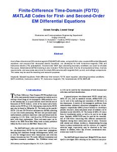
Fig. 1. Time dependent neutron and gamma leakage rate for 24 KT device (reproduced from [14]).
reported later in this paper. This is a simple model of un-collided flux for neutrons and gamma rays (of the average energy) escaping the device. Let the total mean free paths for neutrons and respectively. Furand gammas in ambient air be be the cross-section for secondary conversion. ther, let and are the time dependent leakage rates Then, if (number/unit time) for gammas and neutrons, their uncollided flux at a distance , from the point of detonation, is
(3.3) where (3.4)
Here, is neutron or gamma flux at space point and time due to the particles moving along the direction . The speed and total cross section of the particles in the energy , respectively. The source term has the group are and following form:
is the angle integrated flux for the average energy, referring to either or . The time dependent and leakage rate for a 24 KT nuclear device, taken from [14], are shown in Fig. 1. These of (3.2) for pulses are to be treated as the external source transport calculation. In the approximate transport the model we use the functional form of the pulses given by Fig. 1 and . for the time dependent functions The velocity of neutrons ( 1.9 cm/ns) corresponds to an average energy of 1.5 MeV. The total gamma flux, including secondary ones, may be written as
(3.2)
(3.5)
(3.1)
where, is the cross-section for the neutrons or gammas to be scattered from group to , together with a is the external change of direction from to . Finally, source prescribed by prompt gamma and neutron pulses from the detonation. While the mathematical model outlined above is essential for realistic calculations, an approximate transport model [12] can be used for development purposes, as used to obtain the results
As we are considering the un-collided flux, all the and travel along the radius vector from point of detonation. Since Compton scattering is highly anisotropic, and hence forwardly peaked, we assume that the recoil electrons also move mainly in forward direction. The radial Compton current can then be approximated as [12] (3.6)
1194
IEEE TRANSACTIONS ON ANTENNAS AND PROPAGATION, VOL. 54, NO. 4, APRIL 2006
Here, is the electron charge, is the mean free path of elecis the gamma mean free path for Compton scattrons, and tering. IV. INDUCED AIR CONDUCTIVITY
For all the above equations the electric and magnetic field components are represented on a staggered Yee space lattice [3] with , and calculated at , where and refer to the number of meshes in and directions. The finite difference form of (5.2) is obtained as
Compton electrons collide with the air molecules and produce, on an average, one electron-ion pair for a loss of about 34 and are, respectively, electron deneV of energy [12]. If sity and mobility, then the transient air conductivity is given by (4.1) A simple model for the time development of the electron density, is (5.5)
(4.2) The
rate
of
production is [16]
of
secondary
electrons
In a similar way, it is easy to obtain the equation for as
(4.3) We use in and an empirical fit to the drag coeffiin MeV/m given in [16]. Finally, attachment cient coefficient, [12]. The conductivity is calculated at every space-time point where the e.m fields are computed. It is worth mentioning here that the calculation of space-time dependent air conductivity is very specific of nuclear e.m field propagating through air. This part of the simulation makes the problem a little complicated, as one cannot invoke the wave equation approach, in which the properties of the medium are assumed to be constant in space and time. V. ELECTROMAGNETIC FIELD SOLVER In order to represent the asymmetry produced by the earth, which is responsible for the generation of NEMP, the transport equations, followed by electromagnetic field equations are solved in 2-D cylindrical geometry with azimuthal symmetry. To that end, we assume that the origin of cylindrical coordinates coincides with the detonation point. The current components in cylindrical coordinates are
(5.1) Where, . Electric and magnetic field components, corresponding to the above current distributions are obtained by solving Maxwell’s “curl” equations (5.2) (5.3) (5.4)
(5.6) The magnetic field at half integer time step is
(5.7) Equations [(5.5)–(5.7)] are solved with the assumption that . The field values at the all the fields are zero initially edges are evaluated using metal boundary conditions, which assigns zero fields at top, bottom and right boundaries of 2-D cylindrical FDTD domain. To avoid the (1/r) diverging term in (5.3), the axial electric are obtained by linear interpolation formula fields (5.8) The typical results of our serial code are shown in Figs. 2–5. The radial component of Compton current is plotted as a function of retarded time (t-R/c) at 500 meter from the point of detonation and close to the ground in Fig. 2. Fig. 3 shows the time
RAY et al.: DEVELOPING A FDTD PARALLEL CODE
1195
Fig. 2. Radial component of Compton current at 500 meter from the point of burst.
Fig. 3.
Fig. 4.
Radial electric field at 500 m from the point of burst.
Fig. 5.
Magnetic field at 500 m from the point of detonation.
Air conductivity at 500 m from the point of detonation.
dependence of air conductivity at the same point. The time variation of absolute value of the radial electric field and azat 500 meters are shown in Fig. 4 imuthal magnetic field and Fig. 5 respectively. Actual values of the magnetic field are negative everywhere. VI. NEED FOR PARALLEL COMPUTING Major limitations of FDTD scheme are the simulation errors and execution time. The simulation errors are due to discretization of space and time. The long execution time results from the requirement of a time step needed for accuracy. For stability of the FDTD scheme, one needs to ensure that (5.9)
where c is the speed of light. This criterion is referred to as the Courant–Friedrichs–Lewy (CFL) stability condition [17], [18]. The CFL criterion fixes the maximum possible time step on the basis of smallest spatial mesh size required. Size of the spatial mesh in our case is governed by the requirement of resolving
the highest frequency of interest. This is usually accomplished by using at least 20 meshes per wavelength for that frequency. For illustration, if the frequency is 30 MHz, then the wave; . With length is this mesh size, if the fields are to be simulated at 5 km away number of from the source, then one has to consider at least meshes in each dimension, which is too large to be simulated by serial program. Now, the minimum time step that satisfies CFL leading to about criterion is number of time steps to be simulated. Thus, estimation of very high frequency fields, far away from the source region faces the problem of large memory space and prohibitive computer time for the sequential program. It is this point of view where parallel computing offers affordable execution times for realistic calculations. Apart from the restriction arising from e.m field part, the transport equation also puts some additional conditions for acfluxes. The neutrons and gammas recurate solution of leased in the explosion have a wide range of energy spectrum and all energy groups have different cross-sections. Thus, it is necessary to solve the transport equation taking as many number of energy groups as possible so as to accommodate the various neutron scattering processes for the generation of secondary
1196
IEEE TRANSACTIONS ON ANTENNAS AND PROPAGATION, VOL. 54, NO. 4, APRIL 2006
gamma. The execution time of the transport calculation depends on the following aspects: • number of energy groups; • spatial dimension (1-D, 2-D); • number of discrete scattering angles chosen; • degree of anisotropic scattering. transport It is found that computation time for detailed calculation, involving sufficient number of energy groups runs into several hours [19]. Hence a realistic simulation of NEMP problem is simply not possible by serial program. VII. PARALLEL IMPLEMENTATION For numerical solution of Maxwell’s field equation domain decomposition method has been routinely used. Although Fijany et al. [20] have proposed a methodology for massive temporal parallelism, in contrast to spatial decomposition, by computing all the time steps in parallel, but that method can be applied for homogeneous, isotropic materials, where Maxwell equations can be decomposed into two wave equations. Temporal parallelism cannot be invoked for problems involving heterogeneous medium whose electrical properties change with both space as well as time, as happens in propagating NEMP. The main idea of domain decomposition is to split a discretized FDTD space into sub-domains. The sub-domain computation can be performed in parallel, though some data must be exchanged along the interfaces between sub-domains. We perform the parallel implementation of the serial code on a distributed memory machine composed of processors numbered by , . The global domain is partitioned into strips, each of size , when the domain is decomposed along the direction. If sub-domains are made along direction, then the size of each strip will be . We feed one strip to each processor . fluxes, currents Each of the processors calculates, , , conductivity , electric fields , , and magnetic field for every time step. For domain decomposition along direction, each processor has to calculate the above quantities for and with
Similarly, if the domains are made along direction, then we ; , where have
Thus splitting all time dependent variables among all processors generates a parallel version of the original FDTD code. The synchronization among the processors is fundamental for correct execution of the code, as slight load imbalance could produce an undesired idle time. In order to obtain a good performance, it is necessary to reduce the communication time. However, data passing is a must when the e.m fields on the shared surface of two processors need be computed. FDTD algorithm needs data exchange only with neighboring processors.
The structure of the parallel code using MPI routines is provided in the Appendix. VIII. RESULTS AND DISCUSSION In this section we discuss the results of some test problems. The performance of the parallel program depends on the following aspect: 1. distribution of data in memory and computation task among various processors; 2. parallel algorithm; 3. inter-processor communication: data exchange among neighboring processors; 4. ratio of computation speed to communication speed. Saving in computing time due to increase in number of processors is quantified by means of speed-up parameter and efficiency. Speed-up is defined as the ratio between the simulation times, and , required to run the program on one processor and processors respectively, i.e. (7.1) Efficiency is defined as speed-up per processor (7.2) In designing parallel algorithms one is concerned with maximizing the efficiency. Computation time is proportional to volume of domain and communication time is proportional to its surface. Either or parallelization has to be implemented in such a way that the volume to surface ratio of the domain for a given problem is maximum. We have developed our parallel code on Bhabha Atomic Research Centre’s Parallel computing system, ASHVA, which is made up of 64 Xeon dual processors of 2.4 GHz speed, 512 MB RAM, totaling to 128 processors, and interconnected by Gigabit switch. This is LINUX based parallel platform. With this, we turn to the performance analysis for the examples studied. Ex-1: We are interested to calculate e.m fields at 6 km (typical range of surface burst EMP) from the point of burst and close to the ground. The computation domain has 3000 100 meshes and simulation has to run for time-steps. As large numbers of meshes are required in radial direction, we have decomposed the domain in this direction to reduce the total time. The solid and dashed lines of Fig. 6 show the speed-up for computation part and the overall speed-up. As expected, the speed-up for computation part alone increases steadily with PE’s. The speed-up for overall execution of the program saturates. This is due to the obvious reasons of communication overhead and nonparallelisable part of the program. The communication has two components: i) data exchange at the virtual boundary between neighboring processors (steps 10 and 13 of Appendix) and ii) gathering time-updated variables from all the PE’s to master (step 15). Ex-2: In this case the FDTD lattice dimension is 1200 1200 and point of observation is at 500 500. We have decomposed the domain in -direction. For this problem, even if we decompose the domain in -direction, there will not be any
RAY et al.: DEVELOPING A FDTD PARALLEL CODE
Fig. 6.
Fig. 7.
Speed-up versus number of processors for Ex-1.
Efficiency versus number of processors for Ex-2.
difference in total elapsed time. The efficiency of the parallel code for this example is shown in Fig. 7. It can be easily seen that the computational as well as overall efficiency are more than 100% everywhere and it initially increases with number of PE’s. As the number of PEs increases, the efficiency of the computational task attains a constant value, whereas the overall efficiency follows a steady fall due to increase in communication time. This abnormal behavior of efficiency curve is known as “super-linear” speed up. It is due to higher caching performance provided by a multiprocessor system for smaller data sets due to domain decomposition. The minimum number of PE’s for which the efficiency attains maximum value is dictated by the fact that there is a matching between the memory requirement of problem and the availability of fast memory per processor. The increasing trend of efficiency curve and occurrence of maximum have been observed in other application of electromagnetic wave simulation also, like microwave oven design [21]. Scalability Test: Here, we keep the number of meshes in direction fixed (1000). Domain is decomposed in direction with 100 meshes per processor (domain). This amounts to saying that the problem size is 1000 100, 1000 200, 1000 400 when
1197
Fig. 8.
Elapsed time at master as a function of number of processors.
run with one, two, four processors respectively. In this way, we have simulated a computational lattice of size 1000 2800 by employing total 28 processors. The elapsed times are shown in Fig. 8. Since each of the processors has equal amount of floating point operation, hence the computation time does not change, but the total time taken for entire problem increases. This increase is solely due to the increase in communication time, as shown in Fig. 8. However, it is interesting to note that for 28th fold increase in problem size, the total time increases only by about 10%, which is quite satisfactory when large lattice size is to be considered. The examples studied above show that the efficiency of FDTD parallel codes for simulation of NEMP is quite satisfactory for realistic calculations. The characteristic features of the FDTD algorithm that makes the parallelization of the code very easy and efficient are: • marching (noniterative) method for the space; • explicit method for time differencing; • only nearest neighbor coupling of field variables. IX. CONCLUSION A parallel FDTD code has been developed for estimating the e.m field generated from a nuclear detonation on the surface of the earth, taking into account the features of the neutron and gamma transport. Physics modules of NEMP code are explained. The space decomposition technique seems to be a useful tool for parallelization when we deal with problems involving heterogeneous media. The standard MPI message-passing paradigm is used for ensuring portability. The results show good performance of the code. We have observed that the efficiency of the parallel code decreases after certain number of processors due to the communication delay. It is also observed that the optimum resource utilization occurs at certain number of parallel units depending on the problem size. APPENDIX This Appendix describes the parallel implementation of the NEMP code emphasizing on the steps where MPI routines are used.
1198
1. 2. 3. 4. 5. 6. 7.
8. 9. 10.
11. 12. 13.
14. 15.
Do
IEEE TRANSACTIONS ON ANTENNAS AND PROPAGATION, VOL. 54, NO. 4, APRIL 2006
MPI Initialization: call MPI_INIT (ierr) Setting : call MPI_COMM_SIZE (mpicw, isize, ierr) Allotting IDs: call MPI_COMM_RANK(mpicw, myid, ierr) Define boundaries: , Update currents: call Current (myid, isize) Update conductivity: call Conductivity (myid, isize) Creating neighbors for data exchange: For, : , ; For, : , Update the H fields at all PEs Barrier Synchronization: call MPI_BARRIER(mpicw, ierr) (hp) field: call MPI_SENDRECV Exchange of , , mpir, ibelow, tag, hp ( , , mpir, iabove, tag, mpicw, istatus, ierr) field at all PEs Update Barrier Synchronization field: call MPI_SENDRECV ( Exchange of , , mpir, iabove, tag, er, , , mpir, ibelow, tag, mpicw, istatus, ierr) field at all PEs Update Sending the computed quantities from different processors and receiving them at Master for storage and ), , print: call MPI_SEND (er (iob, mpir, 0, tag, mpicw, ierr)
,
call MPI_RECV (er (iob, ia:ib) mpir, i, tag, mpicw, istatus, ierr) end do
16.
,
End program: call MPI_FINALIZE (ierr).
Notations used in the above refer to: isize- number of processors, myid- process ID, mpicw- MPI_COMM_WORLD, mpir- MPI_REAL, istatus- MPI_STATUS_SIZE elements,. MPI_SEND, MPI_RECV and MPI_SENDRECV are MPI point to point communication routines. Finally, we have used MPI_Wtime for finding the total elapsed time for any job.
[5] D. Davidson, R. W. Ziolkowski, and J. B. Judkins, “FDTD modeling of 3d optical pulse propagation in linear and non-linear materials,” in Proc. Inst. Elect. Eng. 2nd Int. Conf. Computation in Electromagnetics, Nottingham, U.K., 1994, pp. 166–169. [6] R. S. David and L. T. Wille, “Implementation of the finite-difference time-domain method on parallel computers,” Proc. 11th Annual Review of Progress in Applied Computational Electromagnetics, vol. 2, pp. 889–896, Mar. 1995. [7] R. J. Ruebbers, “Three-dimensional Cartesian-mesh finite-difference time-domain codes,” IEEE Antennas Propag. Mag., vol. 36, no. 6, pp. 66–71, Dec. 1994. [8] V. Varadarajan and R. Mittra, “Finite-difference time-domain (FDTD) analysis using distributed computing,” IEEE Microwave Guided Wave Lett., vol. 4, no. 5, pp. 144–145, May 1994. [9] Z. M. Liu, A. S. Mohan, T. A. Aubrey, and W. R. Belcher, “Techniques for implementation of the FDTD method on a CM-5 parallel computer,” IEEE Antennas Propag. Mag., vol. 37, no. 5, pp. 64–71, Oct. 1995. [10] P. S. Pacheco, Parallel Computing with MPI. San Mateo, CA: Morgan Kaufmann, 1997. [11] C. Guiffaut and K. Mahdjoubi, “A parallel FDTD algorithm using the MPI library,” IEEE Antennas Propag. Mag., vol. 43, no. 2, pp. 94–103, Apr. 2001. [12] C. L. Longmire, “On electromagnetic pulse produced by nuclear explosion,” IEEE Trans. Electromagn. Compat., vol. EMC-20, no. 1, pp. 3–13, Feb. 1978. [13] R. Holland, “THREDE- A free-field EMP coupling and scattering code,” IEEE Trans. Nuclear Sci., vol. NS-24, no. 6, pp. 2416–2421, Dec. 1977. [14] H. A. Sandmeier, S. A. Dupree, and G. E. Hansen, “Electromagnetic pulse and time-dependent escape of neutrons and gamma rays from a nuclear explosion,” Nucl. Sci. Eng., vol. 48, pp. 343–352, 1972. [15] E. E. Lewis and W. F. Miller Jr., Computational Methods of Neutron Transport. New York: Wiley, 1984. [16] J. Roger Hill and M. R. Wilson, “Nonlinear self-consistent calculations of radiation induced cylinder skin currents,” IEEE Trans. Nuclear Sci., vol. NS-21, pp. 264–270, Dec. 1974. [17] G. D. Smith, Numerical Solution of Partial Differential Equations: Finite Difference Methods, 3 ed. Oxford, U.K.: Oxford Univ. Press, 1985. [18] A. Taflove and M. E. Brodwin, “Numerical solution of steady-state Electromagnetic scattering problems using the time-dependent Maxwell’s equations,” IEEE Trans. Microwave Theory Tech., vol. MTT-23, no. 8, pp. 623–630, Aug. 1975. [19] A. Ray, G. Kondayya, and S. V. G. Menon, “The effect of detailed multigroup 2D neutron-gamma transport on nuclear electromagnetic pulse,” BARC-ThPD-Rep., 2003. [20] A. Fijany, A. Jensen, Y. R. Samii, and J. Barhen, “A massively parallel computation strategy for FDTD: time and space parallelism applied to electromagnetics problems,” IEEE Trans. Antennas Propag., vol. 43, no. 12, pp. 1441–1449, Dec. 1995. [21] G. Erbacci, G. D. Fabritiis, G. Bellanca, P. Bassi, and R. Roccari, “Performance evaluation of a FDTD parallel code for microwave ovens design,” in Proc. Int. Conf. Parallel Comp. London, U.K., 1999.
REFERENCES [1] J. Lee, R. Lee, and A. Cangellaris, “Time-domain finite-element methods,” IEEE Trans. Antennas Propag., vol. AP-45, no. 3, p. 3, Mar. 1997. [2] W. J. R. Hoefer, “The transmission-line matrix method-theory and applications,” IEEE Trans. Microw. Theory Tech., vol. MTT-33, no. 10, pp. 882–893, Oct. 1985. [3] K. S. Yee, “Numerical solutions of initial boundary value problems involving Maxwell’s equations in isotropic media,” IEEE Trans. Antennas Propag., vol. AP-14, no. 2, pp. 302–307, Mar. 1966. [4] D. P. Rodohan and S. R. Saunders, “Parallel Implementations of the finite difference time domain (FDTD) method,” in Proc. Inst. Elect. Eng. 2nd Int. Conf. Computation in Electromagnetics, Nottingham U.K., 1994, pp. 367–370.
Aditi Ray received the M.Sc. degree in physics from Kalyani University, Calcutta, India, completed the one-year orientation course in nuclear science and technology at Bhabha Atomic Research Centre (BARC), Mumbai, India, and received the Ph.D. degree in physics from the University of Bombay, Bombay, India. She is with the Theoretical Physics Division of BARC since 1992. She has been working in the fields of quantum and nonlinear optics, numerical simulation of propagation of nuclear electromagnetic pulse, high-pressure equation of state, hydrodynamic phenomena, and application of parallel computing systems.
RAY et al.: DEVELOPING A FDTD PARALLEL CODE
G. Kondayya received the M.Sc. degree in physics from Jawaharlal Nehru Technological University, Hyderabad, India, and completed the one-year orientation course in nuclear science and technology at Bhabha Atomic Research Centre (BARC), Mumbai, India. He is with Theoretical Physics Division of BARC since 2001. He has been working on neutral and charged particle transport theory, study of propagation of nuclear electromagnetic pulse, high-pressure equation of state. He is involved in theoretical modeling and numerical simulation of all these phenomena on sequential as well as parallel computing systems.
1199
S. V. G. Menon received the M.Sc. degree in physics from the University of Kerala, completed the one-year orientation course in nuclear science at Bhabha Atomic Research Centre (BARC), Mumbai, India, and received the Ph.D. degree in physics from the University of Bombay, Bombay, India. He is with Theoretical Physics Division of BARC since 1972. His fields of work are in the area of statistical physics, inertial confinement fusion, physics of nuclear reactors, and computational methods.