Our results indicate that DASH7 can be used for robot localization, solving ... A Raspberry Pi [10] ARM processing ... is to represent a posterior belief by a set of K weighted, random ... There are a considerable amount of reflections when.
AMBIENT 2013 : The Third International Conference on Ambient Computing, Applications, Services and Technologies
Robot Localization With DASH7 Technology Jan Stevens, Rafael Berkvens, Willy Loockx and Maarten Weyn Faculty of Applied Engineering - CoSys-Lab University of Antwerp Paardenmarkt 92, B-2000 Antwerp, Belgium {jan.stevens}@ieee.org {rafael.berkvens, willy.loockx, maarten.weyn}@uantwerpen.be Abstract—Robot localization needs to be solved in order to use the robot for other purposes. In this paper, we examine the feasibility of DASH7 tags, operating on the 433 MHz unlicensed band, for locating mobile robots in domestic environments. We achieve the same level of accuracy as laser range finder based localization, while using less processing power. Our results indicate that DASH7 can be used for robot localization, solving the robot localization problem. Keywords—Localization, DASH7, WSN, Robot, AMCL
I.
Fig. 1: Location of the different sensors.
I NTRODUCTION II.
DASH7 is a new, emerging standard for active Radio Frequency Identification (RFID) and uses a 433 Mhz frequency. On the Media Access Control layer it supports Wireless Sensor Networks (WSN), but has many advantages over traditional WSN technologies, as described by Laurijssen et al. [1]. These include lower power usage, improved range, and better battery life. Recent advances in tag development will allow us to use DASH7 in various commercial applications, such as building automation, smart energy, location-based services, mobile advertising, automotive, and logistics within the next few years.
M AIN G OAL
The main goal of this paper is to examine the feasibility of DASH7 tags for locating the robot in a domestic environment. The DASH7 tags’ position in the environment is known. The traditional laser range finder based localization is compared with DASH7 based localization, and DASH7 and laser range finder combined. III.
M ATERIALS
Static landmarks can improve both localization problems. Hahnel et al. [3] showed that RFID technology can be used as static landmarks that improve the global and local localization problem. This paper uses key concepts of the work of Hahnel et al. [3], but uses the new upcoming DASH7 tag technology.
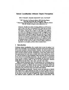
We use a mobile robot equipped with one omni-directional DASH7 antenna mounted on top of the robot. The robot is an off-the-shelf Pioneer P3-DX [4]. It is a standard robot platform that is widely used in the academic world [5]–[8]. It is equipped with a laser range finder, the Sick LMS-100 [9], which is mounted in-front of the robot. The laser range finder is a basic model with a good price/quality ratio and a 270 degrees field of view. For this research, we limit the field of view to 180 degrees. A Raspberry Pi [10] ARM processing unit is used because it is cheap and has a large developer community. The ultrasonic array, that comes by default with the Pioneer P3-DX, is not used in this research. Figure 1 shows the location of the various sensors discussed in this section. The number one indicates the DASH7 receiving tag and two indicates the laser range finder. The left image shows the side view of the robot with the laser range finder in front of the robot. The right image shows the top view of the robot with a DASH7 receiver tag on top of the robot.
The remainder of this paper is organized in the following sections. Firstly, we describe the main goal of this research in the following section. Secondly, in Section III we discuss the used materials for this research. Thirdly, we describe the methods in Section IV. Fourthly, we explain the achieved results in Section V. Finally, in Section VI, we provide a conclusion for this research.
Two different types of antennas are used for the DASH7 receivers and transmitters, as shown in Figure 2. The receivers have a whip antenna, because it performs better than the onboard short Printed Circuit Board (PCB) stub antenna of the transmitters. The transmitters have a holder with two AA batteries to provide power and make them portable, so they can be easily mounted against various objects.
Robot localization in mobile robotics can be divided into two key problems, as shown by Dellaert et al. [2]: global position estimation and local position tracking. The global localization problem deals with a robot that does not know its initial position and has to locate itself. The robot is placed somewhere on the map; therefore, the uncertainty of its location is uniformly distributed over the map. The local localization problem is much easier because the initial position of the robot is known, so only small compensations have to be made for the odometric drift.
Copyright (c) IARIA, 2013.
ISBN: 978-1-61208-309-4
29
AMBIENT 2013 : The Third International Conference on Ambient Computing, Applications, Services and Technologies
on the works of Hahnel et al. [3], which used two directional antennas mounted on the robot to find RFID tags. We use the same idea and create a sensor model from the antenna patterns to update the particle filer and so locate our DASH7 tags. The following aspects need to be considered when creating a sensor model for the DASH7 tag. 1) 2) 3)
Fig. 2: Transmitter tag on the left, receiver tag on the right.
IV.
M ETHODS
A. Bayesian Filtering We use a non-linear recursive Bayesian filter for localizing the robot, explained in Section IV-C. An advanced technique for implementing the recursive Bayesian filter is a particle filter, described by Thrun et al. [11], using the sequential Monte Carlo method [12]. Monte-Carlo Localization (MCL) is a particle filter used for localization and is a version of probabilistic Markov localization, as shown by Burgard et al. [13]. The key concept is to represent a posterior belief by a set of K weighted, random samples called particles. A set of particles represents an approximation of a probability distribution. Particles in MCL contain the robot position, heading direction and a numerical weighting factor analogous to a discrete probability. The algorithm proceeds in three phases: Motion The motion model resembles the movement of the robot. Every particle in the current set is moved according to the motion model. Measurement When the robot sensors are read, the measurements are incorporated in the algorithm. The particles receive a new weight by recalculating the probability of a measurement if the particle is specified. Resampling A new particle set, of K new particles, is created from the current set, by selecting particles from the set, where each new particle is chosen with a probability proportional to the weight of the old particle. This results in particles with a low weight to have a high chance of being ignored, while particles with a high weight to have a high change of being duplicated multiple times. A normalizing factor enforces a probability distribution over all the particles. B. Tag Detection Detecting the DASH7 tags is done by using the Received Signal Strength (RSS). A particle filter, as described in Section IV-A, is used for locating a detected tag. Our idea is based
Copyright (c) IARIA, 2013.
ISBN: 978-1-61208-309-4
There are a considerable amount of reflections when using a 433 Mhz frequency indoor. Additionally, the RSS value will fluctuate even more when tags are not properly aligned. Because of antenna coupling the RSS value will fluctuate within the distance of two times the wavelength.
When using the tags indoor, metal objects will generate reflections that have a lower RSS value than the transmitted power. The orientation of the tag with respect to the receivers on the robot influences the RSS value. When the tags are not aligned, different RSS values are received for the same distance. All these considerations must be taken into account before creating a sensor model. The ratio between the RSS value and the distance from the tag must be determined so the sensor model can be applied correctly. The results in Section V-A indicate that no clear ratio can be extracted from the RSS value alone. A typical directional Yagi antenna for 433 MHz is 75 cm long and 45 cm wide, which is very impractical to mount on the Pioneer P3DX robot. Taking in account the practical limitations and the DASH7 considerations, we adapted our initial idea and decided to use fixed tags in the environment. The algorithm knows the exact location of the DASH7 tags and uses a simplified model to update the weights of the particles. From the results in Section V-A, two different thresholds can be determined. A tag with a received RSS value between 0 dBm and -60 dBm is assumed to be in the range of two meters, and when it has a value between -60 and -80 dBm we assume it is six meters in range. We use lower ranges than described in the results because we have to account for a cluttered environment. This results in ranges for two meters between zero and -70 dBm and for six meters between -70 dBm and -90 dBm. C. Robot Localization The Adaptive Monte Carlo Localization (AMCL) algorithm is used to determine the location of the robot. The AMCL algorithm, as shown by Fox [14], is based on a particle filter discussed in Section IV-A. It lowers the amount of particles needed and improves the performance on the on-board ARM computer. In the first stages of global localization, the robot is completely unaware of where it is. Therefore, a lot of particles are needed to represent this uncertainty. During position tracking, the uncertainty is rather small and can be represented with fewer particles. The key concept of adaptive particle filters is to determine, at each iteration of the particle filter, the number of particles that are needed to represent the true posterior distribution. The main goal of a particle filter is to estimate this posterior. The solution to this problem is to rely on the particle representation in the measurement step, described in Section IV-A, and use it as an estimation of the true posterior.
30
AMBIENT 2013 : The Third International Conference on Ambient Computing, Applications, Services and Technologies
The Kullback-Leibler distance (KL-distance) is a measure of the difference between two probability distributions, as shown by Cover and Thomas [15]. The distance between the sample-based approximation and the true posterior is calculated using the KL-distance, hence the name KLD-sampling.
A multidimensional binary search tree or kd-tree, as shown by Bentley [16], is used to keep track of the different bins. Using a search tree, bins can be easily found and updated. The tree is also used to keep track of multiple hypothesis and calculate their variance and mean. The simplified model for converting a RSS value to a specific distance, discussed in Section IV-B, can then be used in the AMCL algorithm. The calculated distances from the RSS value will determine how the weights of the particles are updated. A particle that is closer to the measured tag than the calulated distance is called an inside particle. A particle that is farther away from the measured tag than the calculated distance is called an outside particle. For these two thresholds the following method is applied. Firstly, if the threshold is two meters, all the inside particles’ weight is multiplied by 0.9, and the outside particles’ weight by 0.1. Secondly, if the threshold is six meters, the inside particles’ weight is multiplied by 0.7, and the outside particles’ weight by 0.3.
V.
R ESULTS
A. Tag Detection An experiment is conducted to determine the ratio between the RSS value and the distance from a tag. A transmitter is fixed at the same approximated height as the tags on the robot. The robot drives slowly away from the tag in a straight line. Every second, the transmitter sends out a packet. The RSS value of those packets are plotted in Figure 3. The described experiment is run in an indoor, open environment. The RSS value first decreases with little fluctuations. After four meters, the robot came near tables and chairs and the RSS fluctuates. When repeating the test in an environment with more objects the RSS value cannot be linked to a specific distance. From this graph, only two possible regions can be identified. The robot is very close to a tag and the robot is somewhere near a tag.
Copyright (c) IARIA, 2013.
ISBN: 978-1-61208-309-4
−60 RSS (dBm)
The KLD-Sampling algorithm calculates the amount of particles needed during the resampling step, as described in Section IV-A. The particles are placed in bins, depending on their location and angle. The bins have a specific size and angle, and can be seen as a 3D histogram, with x, y, and angle as the three dimensions. The algorithm works in the following way: First, a particle is placed in a bin which is then marked as full. Next, all occupied bins are counted and the new amount of particles needed to represent the true posterior distribution is determined. Finally, we see if we have enough particles in the new set and return. The algorithm is repeated for every particle in the current set until the new set has the right amount of particles. When the size of the bins are small then fewer bins are needed in order for the algorithm to stop, compared to a large bin size. The more bins used, the more particles are needed.
−50
−70
−80
2
4
6
8
10
Distance (m)
Fig. 3: The RSS value from a robot that drives away in a straight line from a tag. Experiment is run in an indoor open environment
B. Standard Deviation Before we can use laser range finder based localization, the standard deviation for the particle filter needs to be determined. It influences how the weights are distributed for a laser range finder measurement. We started with a very small distance, making the particles stick closer together, and then slowly increase the distance. The robot drives around and at the last checkpoint, number 15 in Figure 5, we see how far the localization estimation differs from the ground truth. During the experiment we keep track of how many times the particle filter needed to reinitialize itself. This happens when the total weight of all the particles becomes zero. Figure 4 shows the result of the described experiment. The number next to a data point indicates how many times the particle filter reinitialized. The y axis shows the Euclidean distance error for x and y, and the error bars indicated the variance of the hypothesis. On the graph, we see that after 3.5 meters, we do not need any reinitialization of the particle filter. When we look at the acquired accuracy of the localization, using the different parameters, we clearly see that the accuracy staggers after 3.5 meter, meaning that increasing the standard deviation will not result in a increase accuracy of the algorithm. We do see an increasing variance with values above 3.5 meter. The values below 3.5 meter sometimes have a very good accuracy, but also require a high amount of reinitialization. When a higher value than 3.5 meters is used, the robot has more possible hypothesis with a higher variance indicating its uncertainty of its current position estimation. For the reasons described in the results, we use a standard deviation of 3.5 meters. It shows no reinitialization of the particle filter and provides the smallest variance with an equal error, compared with higher distances.
31
AMBIENT 2013 : The Third International Conference on Ambient Computing, Applications, Services and Technologies
10
2
4
8
Error (m)
3 3
3
6 4 2 4
3
3
0
1
0
0
0
0
0.
10 0. 20 0. 50 0. 75 1. 00 1. 25 1. 50 1. 75 2. 00 2. 50 3. 00 3. 50 4. 00 4. 50 5. 00
0
2
Standard Deviation (m)
Fig. 4: Graph showing different tested standard deviation values.
C. Localization Comparison
Figure 6 shows the results of the experiment for every sensor, using the first robot path. We clearly see that laser range finder based localization needs more information before it can converge to the position of the robot. After checkpoint eight, we see that the laser has the same error as other sensors and has around the same variance. For DASH7 based localization, we see that it converges very fast to the right position with a large variance. After checkpoint five the variance lowers and the global localization of the robot turns into local position tracking. This comes because there is a DASH7 tag very close to the starting position of the robot, as indicated in Figure 5. The values are acquired by taking the average value of four measurements using a specific sensor. The x axis show the different checkpoints and the y axis shows the Euclidean distance error for x and y. The combination of DASH7 and laser gives mixed results. The DASH7 tags undo the negative effects of slow convergence from the laser range finder, but do not increase the accuracy of the particle filter. The error is the same for the DASH7/laser localization compared with the DASH7 only localization.
Copyright (c) IARIA, 2013.
ISBN: 978-1-61208-309-4
Fig. 5: Location of the different sensors on the laser generated floorplan.
8
Laser DASH7 Laser & DASH7
7 6 AVG Error (m)
For localizing the robot, the same office environment is used in every experiment. This environment consists of an office, hallway and conference room. Figure 5 gives an overview of two different paths and the location of the different DASH7 transmitting tags. The numbers indicate the different checkpoints, the circles are the DASH7 tags. The top floorplan shows the first path, the bottom figure shows the second path. The localization uses the AMCL algorithm described in Section IV-C. An experiment is conducted to compare the different sensors that are used in the algorithm. At every checkpoint on the different paths, the information about the particle filter is saved. The error value and variance of the best hypothesis is used to compare the different sensors in the AMCL algorithm. This experiment is repeated for every sensor: laser range finder, DASH7 tags, and DASH7 and laser combined.
5 4 3 2 1 0 1 2 3 4 5 6 7 8 9 10 11 12 13 14 15 Checkpoint (#)
Fig. 6: The accuracy of the different sensors compared at the checkpoints using the first path.
32
AMBIENT 2013 : The Third International Conference on Ambient Computing, Applications, Services and Technologies
6 5
0.8
4 Probability
AVG Error (m)
1
Laser DASH7 Laser & DASH7
3 2
0.6 DASH7 Path 1 Laser Path 1 Laser & DASH7 Path 1 DASH7 Path 2 Laser Path 2 Laser & DASH7 Path 2
0.4 0.2
1 0 1
2
3
4
5
6
7
8
9
0
10 11
0
1
2
Checkpoint (#)
Figure 8 shows the Cumulative Distribution Function (CDF) for every sensor in both paths. We see that for path one the DASH7 based localization and Laser and DASH7 localization, outperform the other sensors. For path two, DASH7 achieves the same performances as the laser and combining them results in a better localization. Figure 9 shows the time it takes to acquire a sensor reading and apply this reading in the measurement model of the particle filter. For the experiment we used 1500 particles and took the average of 1000 measurements. The laser range finder and DASH7 use around the same amount of time to read in the sensor information. We clearly see that DASH7 only requires a fraction of the time to update the weights in the measurement model compared with the laser range finder. The results show that DASH7 is five times faster then traditional laser-based localization.
Copyright (c) IARIA, 2013.
ISBN: 978-1-61208-309-4
5
6
7
Fig. 8: CDF for the different paths and sensors.
1
All the different sensors can be used in the AMCL algorithm for successfully locating the robot, and, at the last 4 checkpoints, they have the same accuracy, but a difference in variance. The laser range finder has a higher variance then the DASH7 based localization.
4
Error (m)
Fig. 7: The accuracy of the different sensors compared at the checkpoints using the second path.
DASH7 Laser
0.8 Time (s)
The results of the second path in the same environment are shown in Figure 7. The values are acquired by taking the average value of four measurements using a specific sensor. The x axis show the different checkpoints and the y axis shows the Euclidean distance error for x and y. We see that the laser range finder based localization converges with the same rate as the DASH7 based localization. We explain this by examining both starting positions in Figure 5, for the first path we start next to a tag, so it converges very fast. However, the second path does not start next to a tag so the DASH7 localization needs more information before it can converge to the position of the robot. The combination with DASH7 and the laser range finder does improve the global localization.
3
0.6 0.4 0.2 0 Reading
Processing
Total
Fig. 9: Shows the time it takes for reading a measurement from the DASH7 tags and laser range finder, and applying the measurement in the particle filter.
VI.
C ONCLUSION
In this paper, we presented a new localization method based on DASH7 technology. Our approach involves the use of the AMCL algorithm to localize the robot. We use a simplified sensor model to update the particles. We have successfully implemented our approach and presented with the comparison of the different localization methods. Our results indicate that DASH7 can be used for localization and converges faster than typical laser range finder based localization. Combining laser and DASH7 slightly improves the accuracy of the localization, but results in a more computational heavy algorithm. DASH7 has more advantages than the laser range finder and preforms better in our experiments. It requires less computational power to achieve the same error and variance compared with laser range finder based localization. The amount of tags used in the environment will greatly influence the accuracy of the DASH7 based localization. More research has to be conducted
33
AMBIENT 2013 : The Third International Conference on Ambient Computing, Applications, Services and Technologies
to understand the influence of the amount of tags on the localization. To our knowledge, this is the first implementation of robot localization with DASH7 technology. R EFERENCES [1]
[2]
[3]
[4]
[5]
[6]
D. Laurijssen, E. Vingerhoedt, and M. Weyn, “Opportunistic infrastructure-based dash7 mode 2 localization,” in Master’s Theses Artesis University College Antwerp Department of Applied Engineering: Electronics-ICT, 2012. F. Dellaert, D. Fox, W. Burgard, and S. Thrun, “Monte carlo localization for mobile robots,” in Robotics and Automation, 1999. Proceedings. 1999 IEEE International Conference on, vol. 2. IEEE, 1999, pp. 1322– 1328. D. Hahnel, W. Burgard, D. Fox, M. Philipose, and K. P. Fishkin, “Mapping and localization with RFID technology,” in Robotics and Automation, 2004. Proceedings. ICRA’04. 2004 IEEE International Conference on, 2004, pp. 1015–1020. A. Mobilerobots, “Pioneer 3-dx,” [retrieved: July, 2013]. [Online]. Available: http://www.mobilerobots.com/Libraries/Downloads/ Pioneer3DX-P3DX-RevA.sflb.ashx Y. Mei, Y.-H. Lu, Y. C. Hu, and C. G. Lee, “A case study of mobile robot’s energy consumption and conservation techniques,” in Advanced Robotics, 2005. ICAR’05. Proceedings., 12th International Conference on. IEEE, 2005, pp. 492–497. D. Anguelov, D. Koller, E. Parker, and S. Thrun, “Detecting and modeling doors with mobile robots,” in Robotics and Automation, 2004. Proceedings. ICRA’04. 2004 IEEE International Conference on, vol. 4. IEEE, 2004, pp. 3777–3784.
Copyright (c) IARIA, 2013.
ISBN: 978-1-61208-309-4
[7]
[8]
[9]
[10] [11] [12] [13]
[14]
[15]
[16]
D. Erickson, “Non-learning artificial neural network approach to motion planning for the pioneer robot,” in Intelligent Robots and Systems, 2003.(IROS 2003). Proceedings. 2003 IEEE/RSJ International Conference on, vol. 1. IEEE, 2003, pp. 112–117. B. P. Gerkey and M. J. Mataric, “Sold!: Auction methods for multirobot coordination,” Robotics and Automation, IEEE Transactions on, vol. 18, no. 5, pp. 758–768, 2002. S. Automation, “Lms100/111/120 laser measurement system,” [retrieved: July, 2013]. [Online]. Available: http://www.sick-automation. ru/images/File/pdf/DIV05/LMS100 manual.pdf R. P. Foundation, “Raspberry pi faqs,” [retrieved: July, 2013]. [Online]. Available: http://www.raspberrypi.org/faqs S. Thrun, W. Burgard, and D. Fox, Probabilistic robotics. MIT press Cambridge, MA, 2006, vol. 1. S. Jun and C. Rong, “Sequential monte carlo methods,” Journal of the American Statistical Association, vol. 93, no. 443, pp. 1–032, 1998. W. Burgard, D. Fox, and S. Thrun, “Markov localization for mobile robots in dynamic environments,” Journal of Artificial Intelligence Research, vol. 11, pp. 391–427, 1999. D. Fox, “Kld-sampling: Adaptive particle filters and mobile robot localization,” Advances in Neural Information Processing Systems, pp. 1–12, 2001. T. M. Cover and J. a. Thomas, Elements of Information Theory, ser. Wiley Series in Telecommunications. New York, USA: John Wiley & Sons, Inc., 1991. J. L. Bentley, “Multidimensional binary search trees used for associative searching,” Communications of the ACM, vol. 18, no. 9, pp. 509–517, 1975.
34