Robust algorithms of temperature compensation for electromechanical impedance monitoring in tendon-anchorage Thanh-Canh Huynh1), and *Jeong-Tae Kim2) 1), 2)
Department of Ocean Engineering, PKNU, Busan 608-737, Korea 2)
[email protected]
ABSTRACT In this study, three well-known algorithms of temperature-effect compensation for electromechanical (EM) impedance monitoring at tendon-anchorage of prestressed structures are examined. Firstly, the EM impedance monitoring of prestressed tendonanchorages using the mountable interface technique is visited. Secondly, three algorithms of temperature compensation, including the principle component analysis (PCA), the radial basis function network (RBFN) and the effective frequency shift (EFS) are selected for the impedance-based damage diagnosis in tendon-anchorage under temperature variation. Thirdly, impedance measurements are conducted at tendonanchorage of a lab-scale prestressed concrete (PSC) girder. A lead-zirconate-titanate (PZT) interface is embedded at the tendon-anchorage for indirectly monitoring the impedance response. A series of temperature variation and prestress-loss events are simulated for the lab-scale PSC girder. Finally, the selected temperature-compensation algorithms are employed to adjust the temperature-effect on the measured impedance responses. The prestress-loss diagnosis results using these algorithms are compared to evaluate their applicability for the impedance monitoring under temperature-varying condition.
1. INTRODUCTION Cable/tendon-anchorage is the key subsystem of prestressed structures due to its important responsibility for transferring the prestress force into the main structures. Damage in the tendon-anchorage is often not evident and can result in uncertain states of whole prestressed structures. To ensure the as-built performance, the integrity and the structural safety of the prestressed structures, appropriate damage diagnosis techniques using state-of-the-art condition assessment technologies are needed (Azizinamini 2012).
1) 2)
Graduate Students Professor
Damage diagnosis in structural systems using local dynamic impedance responses has been recognized by many researchers (Liang et al. 1994, Zagrai and Giurgiutiu 2001, Park et al. 2015). To detect structural changes induced by damage at local critical areas, the impedance-based method utilizes the electro-mechanical (EM) impedance sensed by piezoceramic patchs as the local dynamic feature. Since the EM impedance response contains the information about the structural status, damage occurred in the structural systems can be diagnosed by quantifying the variation in the measured impedance signals. The impedance-based method has been proved as a promising local technique due to its practical potential for real damage detection problems. Recently, the impedance-based method has been applied for diagnosing the damage occurrence in the tendon-anchorage of prestressed structures. Kim et al. (2010) conducted the impedance monitoring on a lab-scaled prestressed tendonanchorage. Although changes in the prestress force were successfully detected, it was shown that the effective frequency range was very significant, even over 800 kHz. Nguyen and Kim (2012) and Huynh and Kim (2014) proposed PZT interface technique that can emerge resonant impedance peaks below 100 kHz and reduce the need of high performance impedance analyzers. Min et al. (2016) introduced an effective scheme using the regression analysis for monitoring tensile force and damage in the anchorage system. However, the temperature effect on the tensile force monitoring results was not considered in the experimental evaluation. Temperature-induced variability of local impedance responses should be quantified for the impedance-based damage monitoring. To remove the temperature effect, Park et al. (1999) used a modified root-mean-square-deviation (RMSD) index based on the concept of effective frequency shift (EFS). Koo et al. (2009) proposed a maximum cross-correlation (CC) index to minimize the variation in impedance signatures caused by the variation of temperatures. Sepehry et al. (2011) and Yang et al. (2015) used radial basis function network (RBFN) to compensate errors induced by the temperature change or the external force. Tibaduiza et al. (2013) have applied the principle component analysis (PCA) to compensate the experimental uncertainties such as noise, redundancies, and temperature effect. Previous works by the authors have shown the feasibility of implementing the PZT interface technique in combination with the EFS-based algorithm for the impedance-based prestress-loss diagnosis in prestressed tendon-anchorages under varying temperatures (Huynh and Kim 2014, Huynh et al. 2015a and 2015b, Huynh and Kim 2016). The current study aims to extend the previous studies by examining robust algorithms of temperature-effect compensation for the EM impedance monitoring at the tendon-anchorage. Three well-known algorithms of temperature compensation, including the PCA, the RBFN and the EFS are selected for the impedance-based prestress-loss diagnosis in the tendon-anchorage under temperature variation. The prestress-loss diagnosis results using these algorithms are compared to evaluate their applicability for the impedance monitoring under temperature-varying condition.
2. THEORIES OF IMPEDANCE MONITORING AT TENDON-ANCHORAGE
2.1 Impedance Monitoring using Mountable PZT Interface On the demand to be integrated with the wireless sensing technology (Mascarenas et al. 2007, Hong et al. 2012, Kim et al. 2014) and to predetermine the sensitive frequency band for the impedance monitoring, Huynh and Kim (2014) proposed the mountable PZT interface technique to indirectly monitor the EM impedance response of the prestressed tendon-anchorage system. The interface device is an aluminum beam-like structure mounted on the surface of the bearing plate. The interface structure has a flexible beam section in the middle and the fixed-fixed boundary by two outside contact bodies. A PZT sensor is attached on the interface to monitor the changes in the stress field of the bearing plate that can be induced by the prestress-loss events. In practice, the electric current I() is measured and then it is utilized to calculate EM impedance, as described below (Liang et al., 1994):
V w l Z ( ) i a a I ta
1
T 1 d32xYˆxxE ˆ33 Z a ( ) Z s ( ) 1
(1)
where YˆxxE (1 i )YxxE is the complex Young’s modulus of the PZT patch at zero electric field; ˆxxT (1 i ) xxT is the complex dielectric constant at zero stress; d3x is the piezoelectric coupling constant in x-direction at zero stress; and wa, la, and ta are the width, length, and thickness of the PZT patch, respectively. The parameters and are structural damping loss factor and dielectric loss factor of piezoelectric material, respectively. Eq. (1) shows that the EM impedance, Z(ω), is a combining function of the structural mechanical (SM) impedance of the piezoelectric patch, Za(ω), and that of the host structure (e.g., the interface), Zs(ω). The SM impedance is a function of mass, damping, and stiffness (Liang et al. 1994). Thus, the change in structural parameters (m, k and c) caused by environmental conditions and damage can be represented by the change in the EM impedance. 2.2 Damage Quantification Approach To quantify the change in the EM impedance, the RMSD index can be utilized (Sun et al., 1995). RMSD index is calculated as:
RMSD Z , Z *
N
Z * i Z i i 1
2
N
Z i 1
i
2
(2)
where Z i and Z * i are the impedances measured before and after damage for the i th frequency, respectively; and N denotes the number of frequency points in the sweep.
The correlation coefficient deviation (CCD) index can also be used to quantify the change of the whole impedance signatures (Zagrai and Giurgiutiu, 2001). The CCD index is calculated, as follows:
CCD 1
1
E Re( Z i ) Re( Z ) Re( Z i* ) Re( Z * ) Z * Z
(3)
where E[.] is the expectation operation; Re( Zi ) signifies the real parts of the EM impedances of the ith frequency before and after damage; Re( Z ) signifies the mean values of impedance signatures (real part) before and after damage; and Z signifies the standard deviation values of impedance signatures before and after damage. Note that the asterisk (*) denotes the damaged state. The upper control limit (UCL) of the damage index is adopted to deal with the uncertain conditions occurred in the decision-making alarming damage occurrence as: UCL 3
(4)
where and are mean and standard deviation of the damage index data at undamaged condition, respectively. In Eq. (4), the UCL is determined by three standard deviations of the mean, which is corresponding to 99.7% confidence level (Hong et al. 2012).
3. TEMPERATURE-EFFECT COMPENSATION ALGORITHMS 3.1 PCA-based algorithm PCA linearly transforms an original dataset of variables into a substantially smaller one of uncorrelated variables which can describe most of the information of the original data set (Jlooiffe 1986, Worden and Farrar 2007, Min et al. 2015). From previous experimental studies, it was shown that each resonant peak in an impedance signal has the different nature under the changes in temperature (Huynh et al. 2016). As the result, some resonant ranges may contain much more information of temperature effect than the others. In other words, there are several frequency ranges which produce more significant magnitudes of the damage indices than others under the temperature change. In this study, the PCA algorithm is applied to identify the principle components (PCs) of the damage indices which are computed using subranges of collected impedance signals. To develop the PCA model, it is important to arrange the computed damage indices in a matrix form [DI]mxn which contains the damage indices of n resonant frequency ranges and m impedance samples. When the matrix [DI] is obtained, the covariance matrix [C] can be constructed, as follows:
C
1 T DI DI m 1
(5)
The covariance matrix [C]nxn is a square symmetric nxn matrix which measures the degree of linear relationships within the matrix [DI]. The subspaces in the PCA are defined by decomposing the covariance matrix, as follows:
C A A
T
(6)
where [A] is the matrix whose columns are the eigenvectors, and [] is the diagonal matrix whose diagonal terms are the eigenvalues. Then, the columns of [A] are sorted according to the eigenvalues by descending order. This process gives the PCs of the original dataset in order of significance. By selecting only a reduced number r < n of the PCs, a reduced transformation matrix [AR] ([A] sorted and reduced) can be considered as the PCA model. Then, the original dataset [DI] can be geometrically transformed to the new matrix [Z] which describes the projection of [DI] over the orientations of the PCs, as follows:
Z DI AR
(7)
In case of using full PCs [A] in Eq. (7), the original data can be invertiblely recovered as [DI] = [Z][A]T. In case of using reduced PCs [AR], with the given [Z], the original data can be partially recovered by projecting the matrix [Z] back onto the original n-dimensional space, as follows:
DI R Z AR
T
DI AR AR
T
(8)
The residual matrix [DIE], the error when not using all the PCs, can be obtained by subtracting the original data to that projected back as:
DI E DI DI R DI I AR AR
T
(9)
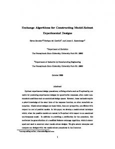
Since only few first PCs govern most of the variability in the damage indices, we could minimize the temperature effect on the damage indices by removing these PCs when constructing the PCA model. In other words, the residual matrix [DIE] in Eq. (9) contain the damage indices after compensating the temperature effect. 3.2 RBFN-based algorithm RBFN is recognized as a powerful curve-fitting tool due to its strong nonlinear processing and approximating features. Sepehry et al. (2011) proposed a method using the ANN based radial basic function (RBF) to minimize the temperature effect on the damage index of impedance-based diagnoses. In this study, to avoid the temperature effect-induced false diagnosis, the RFBN-based technique is implemented to approximate the reference for each impedance measurement at a particular temperature. The RBFN architecture has three layers consisting of an input layer, a
hidden layer with a non-linear RBF activation function and a linear output layer, as illustrated in Fig. 1. The input layer contains the swept frequency of the impedance measurement and the temperature data, while the output layer is defined by the real impedance response. The hidden layer includes the RBF neurons which non-linearly transform the input vector to the hidden space by taking the weights of its input values. The RBF activation function of the RBF neuron j is typically taken to be Gaussian function that is defined as follows:
1 2 x c (10) j 2 2 j in which x is the input vector, cj is the center vector of neuron j and the j is the variance of the Gaussian function. The output of the RBFN is a linear combination of the outputs from the RBF neurons calculated as:
j Exp
N
d j wj
(11)
j 1
where N is the number of RBF neurons, d is the output of the network and wj is the weight of the neuron j. In order to obtain the well-approximated impedance signatures, the RBFN needs to be trained with the appropriate values of the center vector c j, the variance j, and the output weights wj. More detailed information about the learning algorithm for the RBFN can be found in the related publications (Chen et al. 1991, Sepehry et al. 2011, Yang et al. 2015). Real Impedance
Output Layer
Linear Weights
….
Radial Basic Functions
Hidden Layer
Weights Frequency & Temperature
Input Layer
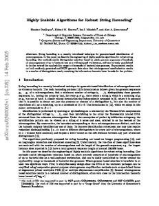
Fig. 1 RBFN architecture used to predict the impedance baseline 3.3 EFS-based algorithm By utilizing the concept of EFS, Koo et al. (2009) proposed an EFS-based temperature-effect compensation method for minimizing false impedance-based diagnoses. The EFS-based technique compensates the temperature effect by shifting an effective frequency () to give the minimum correlation coefficient deviation (CCD)
between the baseline impedance signature, Zo(), and the current impedance signature after temperature change, Z1(). The CCD index after the EFS (CCDEFS) is calculated, as follows:
E Re( Z o (i )) Re( Z o ) Re( Z1 (i )) Re( Z1 ) CCDEFS min 1 Z o Z1
(12)
in which E[.] is the expectation operation; Re( Z o (i )) and Re(Z1 (i )) signifies the real parts of the EM impedances of the ith frequency; Re( Z o ) and Re( Z1 ) signify the mean values of impedance signatures (real part); and Zo and Z1 are the standard deviation values. A loop routine is needed until the value of the minimum CCD is obtained. Fig. 2 shows an ideal scenario for the impedance monitoring with the EFS-based temperature compensation. For the intact state under temperature variation, the temperature change (T) causes approximately the same frequency shift (T) of the resonant impedance peaks (see Fig. 2(a)). Meanwhile, the damage state under temperature change induces the different frequency shift (d+T) of the resonant peaks (see Fig. 2(b)). After the EFS compensation, consequently, the CCDEFS index of the damage state could be much more significant than that of the intact state under the temperature variation. By this way, the structural damage under varying temperature conditions could be alarmed. Intact State at T+T
Intact State after EFS T+T
T
T
CCDEFS 0 Temp. Compensation
by EFS
Impedance
Impedance
T+T
T
Frequency
Frequency
(a) Intact state under temperature variation Damage State after EFS
Damage State at T+T
T+T
d +T,
T
Temp. Compensation by EFS
Frequency
Impedance Impedance
Impedance Impedance
T+T
CCDEFS > 0
T
Frequency
(b) Damage state under temperature variation Fig. 2 EFS-based temperature compensation of impedance monitoring
4. EXPERIMENTAL TESTS ON TENDON-ANCHORAGE 4.1 Test-setup of PSC girder Lab-scale experiments were conducted on a 6.4-meter PSC girder instrumented with a mountable PZT interface at the tendon-anchorage, as shown in Fig. 3(a). The PSC girder was eccentrically prestressed by a 7-wire straight tendon. The prestress forces were introduced into the tendon by a stressing jack. A load cell was installed at the left end to measure the applied prestress force. The tendon was first pre-tensioned to 138.3 kN (14.1 ton) for the intact state. As shown in Fig. 3(b), the aluminum interface was designed and surface-bonded onto the bearing plate of the right anchorage. For the temperature measurement, a K-type thermocouple wire was setup on the top surface of the PSC girder, see Fig. 3(c). The PZT patch on the interface was excited by a harmonic excitation voltage with 1V-amplitude, and the impedance signature was measured by an impedance analyser HIOKI 3532. A static data logger (Kyowa EDX-1 00A) was used to acquire temperature from the K-type thermocouple wire. 4.2 Impedance Testing Scenarios For the first test scenario, the laboratory temperature was controlled to vary between 6.72oC to 22.33oC by heaters while the tendon force was set fixed as 138.3 kN (PS1). A series of tests were performed for seven consecutive days including two days for heating and five days for continuously auto-monitoring, see Fig. 4. The impedance analyzer was set for automatically measuring every 10 minutes with the swept frequency within 10 ~ 55 kHz (901 interval points, 50 Hz frequency interval). Totally, 669 tests were conducted on the PSC girder under the temperature variation. The second test scenario was performed after the first one. The room temperature was controlled almost constant at 19.5oC by air conditioners in the laboratory (Huynh et al. 2016). While the laboratory temperature was handled to nearly constant, a set of prestress-loss events was simulated to the PSC girder from which the impedance responses of the PZT interface were measured for detecting the prestress-loss. Five prestressing levels: PS1= 138.3 kN, PS2 = 128.5 kN, PS3 = 117.7 kN, PS4 = 108.9 kN, and PS5 = 99.1 kN were set for the test structure. By each prestressing level, five sets of impedance were sampled. Totally, 25 tests were acquired from the PZT interface under the near-constant temperature.
Anchor Block Stressing Jack
Load Cell Indicator
Bearing Plate PZT Interface
Thermocouple Wire
Support
Top ofofPSC Girder (a) PSC girder (b) Anchorage zone (c) Top PSC girder Anchorage Zone PSC Girder Fig. 3 Experimental setup in PSC girder (Huynh and Kim 2016)
25 Test # 1 Test #114
Temperature ( oC)
Test #363
Test #501
20
15
10 Heater on
5 2015/01/28
01/29
Heater off
01/30
01/31
02/01
02/02
02/03
02/04
Time
Fig. 4 Time histories of temperature variation simulated in the laboratory 4.3 Impedance Responses of Tendon-Anchorage Fig. 5 shows the 669 impedance samples in 10-55 kHz measured from the intact tendon-anchorage for temperatures 6.72oC ~ 22.33oC (the first test scenario). It is worth noting that the impedance samples corresponding to temperatures 18.5 oC ~ 22oC were not measured due to the quick drop of the laboratory temperature after turning the heaters off, see Fig. 4. As observed from Fig. 5, the temperature variation caused significant horizontal and vertical shifts of the impedance signals. The impedance signals were zoomed in for the frequency range of 26.5-27.5 kHz, as plotted in Fig. 5. Noticing that the impedance amplitude varied significantly when the temperature changed. Fig. 6 shows real impedance signatures in 10-55 kHz for the healthy state PS1 and four damage cases PS2 ~ PS5 under the near-constant temperature about 19.5oC. A resonant frequency range of 25-35 kHz was zoomed in and also plotted in Fig. 6. As observed from the figure, the resonant peaks tended to sensitively shift left according to the decrement of prestress force. This indicates that modal stiffness of the PZT interface decreased with the prestress-loss of the PSC girder.
1000 800 600 400
300
200
100
0 21
200
20.5
0 10
15
20
26.5-27.5 kHz
1200
Impedance RealReal (Ohm) Impedance (Ohm)
400 Real Impedance (Ohm)
Real Impedance (Ohm)
1200
25
30
02/04 20
Frequency Frequency (kHz)
02/02
35 19.5 (kHz)
40 15/01/29
01/31 45 Time
50
1000 800 600 400 200 0 28 27.5
02/04
27
02/02 26.5
55
01/31 26
Frequency (kHz)
o
15/01/29
Time
o
Fig. 5 Impedance signals in 10-55 kHz and 26.5-27.5 kHz at 6.72 C ~ 22.33 C
900
900
Real Impedance (Ohm)
700 600
138.3 kN 128.5 kN 117.7 kN 108.9 kN 99.1 kN
500 400 300
700 600
400 300 200
100
100 15
20
25
30 35 Frequency (kHz)
40
45
50
55
138.3 kN 128.5 kN 117.7 kN 108.9 kN 99.1 kN
500
200
0 10
PS1 = PS2 = PS3 = PS4 = PS5 =
800 Real Impedance (Ohm)
PS1 = PS2 = PS3 = PS4 = PS5 =
800
0 25
30 Frequency (kHz)
35
Fig. 6 Impedance signals in 10-55 kHz and 25-35 kHz at various prestress forces
5. PERFORMANCE EVALUATION OF SELECTED ALGORITHMS 5.1 Temperature Compensation by PCA-based Algorithm Once the impedance signals were measured from the PZT interface, the frequency range of 10-55 kHz was first divided into seven narrow subranges with the same frequency interval of 5 kHz. They are Range 1 of 11-16 kHz, Range 2 of 16-21 kHz, Range 3 of 21-26 kHz, Range 4 of 26-31 kHz, Range 5 of 31-36 kHz, Range 6 of 36-41 kHz and Range 7 of 41-46 kHz. The frequency interval was determined so that each subrange contains one clear resonant peak. Next, the CCD index of the seven subranges were computed for the intact and damage cases, as shown in Fig. 7. Intact PS1, 6.72~22.33 oC
Prestress-loss PS1~PS5, 18.80~19.96 oC
140 Range 1 Range 2
Original CCD Index (%)
120
Range 3 Range 4
Range 5 Range 6
Range 7
600 669 Test Number
675
100 80 60 40 20 0
1
100
200
300
400
500
680
685
690
694
Fig. 7 Original CCD index of 7 frequency ranges under intact and prestress-loss cases
-0.5
0
0.5
1
-0.5
0
0.5
1
-0.5
0
0.5
1
-0.5
0
0.5
1
-0.5
0
0.5
1
-0.5
0
0.5
1
-0.5
0
0.5
1
90 80 70
Variance (%)
PC1 PC2 PC3 PC4 PC5 PC6 PC7
100
1 0 -1 -1 1 0 -1 -1 1 0 -1 -1 1 0 -1 -1 1 0 -1 -1 1 0 -1 -1 1 0 -1 -1
60 50 40 30 20 10 0
Fig. 8 PCs of original CCD indices Intact PS1, 6.72~22.33 oC
CCD Index After Removing PC1, PC2 (%)
100
Range 1 Range 2
80
PC1
PC2
PC3
PC4
PC5
Prestress-loss PS1~PS5, 18.80~19.96 oC
Range 3 Range 4
Range 5 Range 6
Range 7
600 669 Test Number
675
60 40 20 0 -20 -40 -60
1
100
200
300
400
500
680
685
690
694
Fig. 9 CCD index of 7 frequency ranges after removing PC1 and PC2 The matrix [CCD]669x7 that contains the CCD values of 7 ranges and 669 impedance samples (under the intact state) was constructed by using Test 114 at 12.63 oC as the impedance reference. Using Eqs. (5) and (6), the PCs of the CCD matrix were computed, as plotted in Fig. 8. Next, the original CCD data was transformed into the new coordinate system (PC1~PC7). The PCA transformation ensures that the axis PC1 has the most variation, the axis PC2 is the second-most, and the axis PC7 is the least, see Fig. 8. Using Eqs. (7)~(9), PC 1 and PC2 were removed from the PCA model, then the CCD matrix was projected back to the original coordinate system, as shown in Fig. 9. As shown in Fig. 9, the temperature-induced variation of the CCD indices of Ranges 1~7 significantly reduced after implementing the PCA-based algorithm. To consider the contribution of all resonant ranges to the damage severity evaluation, therefore, the mean values of the CCD indices along the seven subranges were computed as the final damage index. Fig. 10 shows the control chart for decisionmaking on the prestress-loss occurrence in the PSC girder. The UCL of the final damage index was computed as 1.61%. The small value of the UCL indicates that the temperature effect has been well-compensated by the PCA model. It is observed from Fig. 10 that all four prestress-loss events (PS2~PS5) were successfully detected by the final damage index. Also, the final damage index increased when the damage severity went up.
PC6
PC7
25
Temperature: 6.72~22.33 oC
Temperature: 18.80~19.96 oC
Damage Index (%)
20
15
PS2 = 129 kN
10
Intact PS1 = 138 kN
5
PS3 = 118 kN
PS4 = 109 kN
PS5 = 99 kN
UCL = 1.61% 0 1
100
200
300
400
500
600 669 Test Number
675
680
685
690
694
Fig. 10 Prestress-loss monitoring results using PCA-based algorithm 5.2 Temperature Compensation by RFBN-based Algorithm Remind that the impedance samples were measured for 901 swept frequencies ranging from 10 to 55 kHz with 50 Hz interval. For estimating the impedance values at the 901 swept frequencies, totally, 901 RBF networks were constructed. The 669 impedance samples (the intact case at temperatures 6.72oC ~ 22.33oC) were adopted to train the 901 RBF networks. For each network, the input was its swept frequency and the temperature data, and the output was the real impedance data. The good accuracy and efficiency can be achieved using the 50 RBF neurons for each RBF networks. K-Means clustering was used to select the center vectors for the RBF neurons. The variance of the cluster was set at 0.5 to use for all neurons. The neuron activation values were normalized to improve the accuracy of the function approximation problem. 1200
1200
CCD = 0.11%
CCD = 0.20% 1000
Real Impedance (Ohm)
Real Impedance (Ohm)
1000
Measured Impedance Estimated Impedance
800
600
400
200
0 10
Measured Impedance Estimated Impedance
800
600
400
200
15
20
25
30 35 40 Frequency (kHz)
45
50
(a) Test 1 at 22.33 oC (trained)
55
0 10
15
20
25
30 35 40 Frequency (kHz)
45
50
55
(b) Test 114 at 12.57 oC (trained)
1200
1200 Measured Impedance Estimated Impedance
CCD = 0.12%
Measured Impedance Estimated Impedance
CCD = 2.74% 1000
Real Impedance (Ohm)
Real Impedance (Ohm)
1000
800
600
400
800
600
400
200
200
0 10
15
20
25
30 35 40 Frequency (kHz)
45
50
(c) Test 363 at 6.72 oC (trained)
0 10
55
15
20
25
30 35 40 Frequency (kHz)
45
50
55
(d) Test 670 at 19.49 oC (untrained)
Fig. 11 Impedance responses predicted by RBFN-based algorithm 80
Temperature: 6.72~22.33 oC Training Data
70
Temperature: 18.80~19.96 oC
CCD Index (%)
60 50 40 30 20 10 0
Intact PS1 = 138 kN
UCL = 2.84% 1
100
200
300
400
PS2 = 129 kN 500
600 669 Test Number
675
PS3 = 118 kN 680
PS4 = 109 kN 685
PS5 = 99 kN 690
694
Fig. 12 Prestress-loss monitoring results using RBFN-based algorithm The performance of the trained RBF networks was evaluated by estimating the impedance values for the 901 swept frequencies with given temperatures. Fig. 11 shows the comparisons between the measured impedance samples and the estimated ones by the RBFNs for the temperatures 22.33 oC (Test 1), 12.57 oC (Test 114), 6.72 o C (Test 363), and 19.49 oC (Test 670). Note that Test 670 was the untrained test and the temperature 19.49 oC of Test 670 was the untrained temperature, as stated previously. The correlation between two samples (measured and estimated) was calculated using the CCD index, see Fig. 11. As observed from the figure, the measured impedance signals and the estimated ones were well-matched each other with very small deviations. It is found that the correlation level (CCD index) was slightly higher for the untrained test. Despite those, these observations have proved the reliability of using the RBFNs for the approximation of the impedance baseline at a given temperature. Finally, the swept frequencies and the temperature data of the 694 tests under the intact and prestress-loss cases were used as the input to estimate the baselines of the 694 measured impedance samples. The CCD index was computed by comparing
the measured impedance signals with the estimated baselines over the frequency range 10-55 kHz, as shown in Fig. 12. It is found that the temperature effect was wellcompensated on the CCD index, and the UCL of the CCD index was 2.84%. As shown in the figure, all four prestress-loss scenarios in the PSC girder were successfully diagnosed by the CCD index. It can be seen that the CCD index increased according to the ascending prestress-loss severity, reflecting the natural characteristics of the damage indices. 5.3 Temperature Compensation by EFS-based Algorithm After measuring the impedance samples, the selecting process of appropriate frequency range for the temperature-effect compensation was performed. Several resonant ranges of the impedance signatures (for the intact case) within 10-55 kHz were examined. Fig. 13 shows the CCDEFS values for five tested frequency ranges: 1247 kHz, 17-41 kHz, 23-35 kHz, 25-35 kHz, and 25-30 kHz. Test 1 at 22.33 oC was selected as the reference impedance. It is found that the wide frequency bands have much more significant CCDEFS values than the narrow band. As observed from Fig. 13, the frequency range of 25-30 kHz which has very small values of the CCDEFS (less than 3%), can be selected for the temperature-effect compensation. 30
CCDEFS Index (%)
25
12-47 kHz
17-41 kHz
25-35 kHz
25-30 kHz
23-35 kHz
20 15
10 5 0 5
7
9
11
13
15
17
19
21
23
Temperature (oC)
Fig. 13 CCDEFS index of various frequency ranges (Reference: Test #1) Fig. 14 shows the Test 1 and the Test 363 impedance signatures in 25-30 kHz measured from the intact tendon-anchorage at 22.33 oC and 6.72 oC, respectively. Before the EFS, a considerable CCD value, 56.4%, can be observed between two impedance signatures. After the EFS, however, the CCD value was significantly reduced to 2.9%. For two close temperatures of two consecutive days: Test 363 at 6.72 o C and Test 501 at 7.19 oC, the CCD value remained the same as very small as 0.6% for before and after the EFS, see Fig. 15. These results indicate that the temperatureeffect was mostly compensated when the narrow frequency range of 25-30 kHz was employed. Next, the CCDEFS index was calculated for all 694 impedance samples including 669 samples for the intact conditions (6.72 oC ~ 22.33 oC) and 25 samples for five prestress levels (18.8 oC ~ 19.96 oC). Here, the impedance measurement at 12.63 oC (Test 114) was set as the reference impedance. Fig. 16 shows the CCDEFS index that
was computed over the selected frequency range of 25-30 kHz. It is found that the UCL of the CCDEFS index was significantly small at 2.1% and the CCDEFS values jumped over the upper control limit for all prestress-loss levels. This means all prestress-loss events occured in the PSC girder were successfully alarmed by the CCDEFS index. Basically, the damage index supposes to rise as the damage severity increases. However, as observed in Fig. 16, the CCDEFS index increased rapidly after the first prestress-loss event, but remained nearly constant for the others. This implies that the natural characteristic of the damage index was not remained after the EFS-based temperature compensation.
1200
0.5 Test #1 at 22.33oC
Test #1 at 22.33oC
o
Test #363 at 6.72 C
0.4 Normalized Z()
CCD = 56.4 %
Real Z()
800
400
CCDEFS = 2.9 %
Test #363 at 6.72oC
0.3
0.2
0.1
0
25
26
27 28 Frequency (kHz)
29
0
30
(a) Impedance before EFS
25
26
27 28 Frequency (kHz)
29
30
(b) Normalized impedances after EFS
Fig. 14 Impedance signals in 25-30 kHz for two temperatures: 22.33 oC vs 6.72 oC
1200
0.5 o
Test #363 at 6.72oC
Test #363 at 6.72 C o
Test #501 at 7.19 C
0.4 Normalized Z()
CCD = 0.6 %
Real Z()
800
400
CCDEFS = 0.6 %
Test #501 at 7.19oC
0.3
0.2
0.1
0
25
26
27 28 Frequency (kHz)
29
(a) Impedance before EFS
30
0
25
26
27 28 Frequency (kHz)
29
30
(b) Normalized impedances after EFS
Fig. 15 Impedance signals in 25-30 kHz for two close temperatures 6.72 oC vs 7.19 oC
6
Temperature: 6.72~22.33 oC
Temperature: 18.80~19.96 oC
CCD
EFS
Index (%)
5
4
3
UCL = 2.1% 2
1
0
PS2 = 129 kN
Intact PS1 = 138 kN 1
100
200
300
400
500
600 669 Test Number
675
PS3 = 118 kN
680
PS4 = 109 kN 685
PS5 = 99 kN 690
694
Fig. 16 Prestress-loss monitoring results using CCDEFS (Reference: Test #114) 5.4 Comparison of PCA, RBFN and EFS algorithms To evaluate the accuracy, the damage indices calculated previously by the three algorithms (i.e., PCA, NRBN, and EFS) were compared with the exact damage index. Note that Tests 670~694 (25 samples) measured during the second test scenario under the near-constant temperature condition were utilized for the accuracy evaluation. Fig. 17 shows the CCDPCA, CCDRBFN and CCDEFS indices computed by three examined temperature compensation methods in comparison with the exact CCD index. Note that the exact CCD index was computed over the whole measured frequency range of 1055 kHz. It is shown that the changing trends of the CCDPCA and CCDRBFN indices under PS1~PS5 were well-consistent with that of the exact CCD index, meanwhile the CCDEFS index remained nearly unchanged for PS2~PS5. It is also observed that the magnitudes of the CCDEFS and CCDPCA indices were much smaller than that of the CCDRBFN index, see Fig. 17. This means the RBFN-based method can produce most accurate damage index for the impedance monitoring in the prestressed tendonanchorage. However, to conduct the RBFN-based analysis, the temperature data needs to be sufficiently monitored and synchronized with the impedance samples. 80
PS2 CCD
PS3
PS4
PS1
PS5
PS2
PS3
110 100
Exact
RMSD
Exact
CCDEFS
90
RMSDPCA
60
CCD
80
RMSD
50
CCDRBFN
PCA
Damage Index (%)
Damage Index (%)
70
PS1
40 30
RBFN
70 60 50 40 30
20
20 10 0 670
10 675
680 685 Test Number
690
695
0 670
675
Fig. 17 CCD indices after temperature-effect compensation by three algorithms
680 685 Test Number
PS4
6. CONCLUSION In this study, robust algorithms of temperature-effect compensation for EM impedance monitoring at tendon-anchorage of prestressed structures were examined. Firstly, the EM impedance monitoring of prestressed tendon-anchorages using the mountable interface technique was visited. Secondly, three well-known algorithms of temperature compensation, including the EFS, the PCA and the RBFN were selected for the impedance-based damage diagnosis in tendon-anchorages under temperature variation. Thirdly, impedance measurements were carried out at tendon-anchorage of a lab-scale PSC girder. A series of temperature variation and prestress-loss events were simulated for the lab-scale PSC girder. Finally, the selected temperature-compensation algorithms were employed to adjust the temperature-effect on the measured impedance responses. The prestress-loss diagnosis results using these algorithms were compared to evaluate their applicability for the impedance monitoring under temperature-varying condition. From the performance valuation of the three algorithms, it can be concluded that the RBFN-based algorithm can produce most accurate diagnosing results for the impedance monitoring in the prestressed tendon-anchorage if the temperature data is sufficiently measured. In case of lack of the temperature information, the PCA-based method could be used as an alternative method to minimize the temperature effect on the damage diagnosis results.
ACKNOWLEDGMENTS This work was supported by Basic Science Research Program through the National Research Foundation of Korea (NRF) funded by the Ministry of Education, Science and Technology (NRF-2013R1A1A2A10012040). The graduate student involved in this research was also supported by the Brain Korea 21 Plus program of Korean Government.
REFERENCES Azizinamini, A. (2012), “Improved inspection techniques for steel prestressing/posttensioning strand”, Florida International University. Chen, S., Cowan, C.F.N. and Grant, P.M. (1991), “Orthogonal Least Squares Learning Algorithm for Radial Basis Function Networks”, IEEE Tra. Neu. Net., 2(2), 302-309. Hong, D.S., Nguyen, K.D., Lee, I.C. and Kim, J.T. (2012), "Temperature-compensated damage monitoring by using wireless acceleration-impedance sensor nodes in steel girder connection", Inter. Jour. Distr. Sens. Net., 2012, 1-12. Huynh, T.C. and Kim, J.T. (2014), “Impedance-based cable force monitoring in tendonanchorage using portable PZT-interface technique”, Math. Probl. Eng., 2014, 1-11. Huynh, T.C., Park, Y.H., Park, J.H. and Kim, J.T. (2015a), “Feasibility verification of mountable PZT-interface for impedance monitoring in tendon-anchorage”, Shock Vibration, 2015, 1-11.
Huynh, T.C., Lee, K.S., and Kim, J.T. (2015b), “Local dynamic characteristics of PZT impedance interface on tendon anchorage under prestress force variation”, Sma. Struc. Syst., 15(2), 375-393. Huynh, T.C., Park, Y.H., Park, J.H., Hong, D.S., and Kim, J.T. (2015c), “Effect of temperature variation on vibration monitoring of prestressed concrete structures”, Shock and Vibration, 2015, 1-9. Huynh, T.C., Park, J.H., and Kim, J.T. (2016), “Impedance monitoring at tendonanchorage via mountable PZT interface and temperature-effect compensation”, Proc. SPIE, 9799, 1-6. Huynh, T.C., and Kim, J.T. (2016), “Compensation of temperature effect on impedance responses of PZT interface for prestress-loss monitoring in PSC girders”, Smart Structures and Systems, 17(6), 881-901. Jlooiffe, I.T. (1986), “Principal Component Analysis”, Springer, New York. Koo, K.Y, Park, S.H., Lee, J.J., and Yun, C.B. (2009), “Automated impedance-based structural health monitoring incorporating effective frequency shift for compensating temperature effects”, Jour. Intell. Mat. Syst. Struc., 20, 367-377. Kim, J.T., Huynh, T.C. and Lee, S.Y. (2014), “Wireless structural health monitoring of stay cables under two consecutive typhoons”, Struct. Monit. Maint., 1(1), 47-67. Kim, J.T., Park, J.H., Hong, D.S. and Park, W.S. (2010), “Hybrid health monitoring of prestressed concrete girder bridges by sequential vibration-impedance approaches”, Engineering Structures, 32, 115-128. Liang, C., Sun, F.P. and Rogers, C.A. (1994), “Coupled electro-mechanical analysis of adaptive material - Determination of the actuator power consumption and system energy transfer”, J. Intel. Mat. Syst. Str., 5, 12-20. Mascarenas, D.L., Todd, M.D., Park, G. and Farrar, C.R. (2007), “Development of an impedance-based wireless sensor node for structural health monitoring”, Smart Materials and Structures, 16(6), 2137-2145. Min, J., Yi, J.H., and Yun, C.B. (2015), “Electromechanical impedance-based long-term SHM for jacket-type tidal current power plant structure”, Sma. Struc. Syst., 15(2), 283-297. Min, J., Shim, H., Yun, C.B., Hong, J.W. (2016), “An electromechanical impedancebased method for tensile force estimation and damage diagnosis of post-tensioning systems”, Sma. Struc. Syst., 17(1), 107-122. Nguyen, K. D. and Kim, J. T. (2012), “Smart PZT-interface for wireless impedancebased prestress-loss monitoring in tendon-anchorage connection,” Sma. Struc. Syst., 9(6), 489–504. Park, J.H., Kim, J.T., Hong, D.S., Mascarenas, D. and Lynch, J.P. (2010), “Autonomous smart sensor nodes for global and local damage detection of prestressed concrete bridges based on accelerations and impedance measurements”, Sma. Struc. Syst., 6, 711-730. Park, J.H., Huynh, T.C., and Kim, J.T. (2015), “Temperature effect on wireless impedance monitoring in tendon anchorage of prestressed concrete girder”, Sma. Struc. Syst., 15(4), 1159-1175. Park, G., Kabeya, K., Cudney, H., and Inman, D. (1999), “Impedance-based structural health monitoring for temperature varying applications”, JSME Int. J. Ser. A Solid Mech. Mater. Eng., 42, 249–258.
Sepehry, N., Shamshirsaz, M., and F. Abdollahi (2011), “Temperature variation effect compensation in impedance-based structural health monitoring using neural networks”, J. Intel. Mat. Syst. Str., 20(10), 1-8. Sun, F.P., Chaudhry Z., Liang, C. and Rogers C.A. (1995), “Truss structure integrity identification using PZT sensor-actuator”, Jour. Intell. Mat. Syst. Struc., 6, 134-139. Yang, J., Zhu, H., Wang, D. and Ai, D. (2015), “The compensation technique of tensile force effect on the electro-mechanical impedance method for structural health monitoring”, Jour. Intell. Mat. Syst. Struc., 1-12. Zagrai, A. N. and Giurgiutiu, V. (2001), “Electro-mechanical impedance method for crack detection in thin plates”, Jour. Intell. Mat. Syst. Struc., 12, 709-718. Worden, K. and Farrar, C. (2007), “Philosophical Transactions of the Royal Society”, Series A, 365(1861) 299-632.