Sung I. Kim TRW Systems, Redondo Beach, California 90278 e-mail:
[email protected]
Robert G. Landers University of Missouri-Rolla, Department of Mechanical and Aerospace Engineering and Engineering Mechanics, Rolla, Missouri 65409-0050 e-mail:
[email protected]
A. Galip Ulsoy University of Michigan, Department of Mechanical Engineering, Ann Arbor, Michigan 48109-2125 e-mail:
[email protected]
Robust Machining Force Control With Process Compensation Force control is an effective means of improving the quality and productivity of machining operations. Metal cutting force models are difficult to accurately generate and, thus, there is large uncertainty in the model parameters. This has lead to investigations into robust force control techniques; however, the approaches reported in the literature include known process changes (e.g., a change in the depth-of-cut) in the model parameters variations. These changes create substantial variations in the model parameters; thus, only loose performance bounds may be achieved. A novel robust force controller is presented in this paper that explicitly compensates for known process effects and accounts for the force-feed nonlinearity inherent in metal cutting operations. The controller is verified via simulation and experimental studies and the results demonstrate that the proposed controller is able to maintain tighter performance bounds than robust controllers that include known process changes in the model parameter variations. 关DOI: 10.1115/1.1580849兴
Introduction Force control is an effective means of improving the quality and productivity of machining operations. One of the greatest difficulties in regulating metal cutting processes is that these processes are inherently nonlinear and vary significantly under normal operating conditions. Analytical models of machining force processes are currently not available; therefore, empirical techniques are often utilized. Adaptive approaches have been typically studied in machining force control to account for changes in the force process. Many researchers have implemented Model Reference Adaptive Control 共MRAC兲 systems to regulate machining forces 关1– 4兴. Adaptive control schemes rely on the controller’s ability to perform the required on-line estimation. Thus, adaptive controllers are difficult to design, analyze, and implement due to their complexity. There has also been much interest in model-based and robust control approaches for machining force regulation. Harder 关5兴 linearized the force process and applied standard control techniques to design a fixed gain controller. However, the small perturbation assumption cannot be guaranteed, and the performance of this approach is sensitive to force-feed and force-depth effects. The linearization technique was augment in 关6兴 to directly account for changes in the depth-of-cut. Landers and Ulsoy 关7兴 explicitly accounted for the force-feed and force-depth nonlinearities. This approach uses a change of variable to account for the force-feed nonlinearity and adjusts the controller gains to account for the force-depth nonlinearity. This methodology preserves the ease of design of linear, model-based techniques while being robust to changes in the depth-of-cut and ensuring stability under a range of parameter variations. Chen and Chang 关8兴 designed a robust proportional plus integral 共PI兲 controller that guarantees stability under a range of model uncertainty. Their regulator was designed for the mean value of a certain operating range of the process parameters and tuned to be stable within this entire range. The idea was straightforward, but the design method led to a rather restricted system. Robust adaptive control approach has been investigated by a number of researchers. Carillo et al. 关9兴 designed a delta approach robust adaptive controller. In their work, a Linear Quadratic Guassian 共LQG兲 controller was designed to take advantage of LQG’s guaranteed robust properties for Single-Input Single-Output Contributed by the Manufacturing Engineering Division for publication in the JOURNAL OF MANUFACTURING SCIENCE AND ENGINEERING. Manuscript received July 2001; revised December 2002. Associate Editor: T. Kurfess.
共SISO兲, linear systems. Then, nonlinear parameters between the feed and the force are estimated using an adaptive strategy to decrease the bias of the linear model approach. However, their approach assumes a linear relationship between the force and the depth-of-cut, and it does not yield explicit performance robustness other than LQG’s guaranteed robustness margins. Hayes et al. 关10兴 designed a robust controller in the continuous domain using Quantitative Feedback Theory 共QFT兲. Their simulation results showed satisfactory responses over a range of cutting conditions, thereby demonstrating the effectiveness of the method. Punyko and Bailey 关11兴 and 关12兴 proposed QFT designs in the discrete domain utilizing the delta transform. Their designs were based on a linear plant with uncertainty on pole and zero locations as well as the magnitude of a gain factor that indirectly accounts for variations in depth-of-cut and nonlinear process parameters. The controller was verified through simulations but was not implemented on-line. Rober et al. 关13兴 augmented the discrete QFT design in 关12兴 and implemented the controller on-line. Once again, their design was based on a linear plant, and the depth-ofcut and force-feed nonlinearity were accounted for indirectly as uncertainty in pole/zero locations and a gain factor in the transfer function of the linear plant. Their experimental results showed performance robustness for a small change in the depth-of-cut only. In this paper a robust machining force controller with process compensation is developed using QFT concepts. Unlike many of the other studies that have utilized QFT, the controller designed in this paper explicitly accounts for the nonlinear force-feed relationship using the transformation in 关7兴 and contains so-called process compensation. Process compensation is a technique whereby controller gains are adjusted to explicitly account for changes in process parameters that are known or measurable. Without process compensation, these changes would need to be incorporated into the model parameter variations creating greater parameter bounds and correspondingly looser performance bounds. Another benefit is that iterations are not required in the design of the proposed controller. The results from this controller are compared, via simulation and experimental studies, to results using a robust controller without process compensation.
Machining Force Process Modeling The cutting force model used in this paper is a nonlinear, static model of the face milling process. Static models are used when regulating force signals that are sampled once per spindle revolution such as a maximum or average force. Static force signals are
Journal of Manufacturing Science and Engineering Copyright © 2003 by ASME
AUGUST 2003, Vol. 125 Õ 423
typically utilized for cutting processes having inherent force fluctuations during the spindle revolution 共e.g., milling applications兲. The structure of the static machining force process, including nonlinear effects, is 关7兴 F 共 t 兲 ⫽Kd  f ␣ 共 t 兲
(1)
where K, , and ␣ are empirically determined model parameters, and d 共depth-of-cut兲 and f 共feed兲 are process parameters whose nominal values are given by a part program. This model is for a constant cutting speed. Effects such as tool wear and cutting temperature also affect the force process. If they are not included explicitly in the empirical model, their effect may be modeled as variations in the model parameters, particularly the parameter K. The variations in the process parameters are sometimes known or may be measured. For example, if a part surface is machined after the initial layer of the casting is removed, the depth-of-cut will be known. This information may be incorporated into the force controller. In milling operations, the parameter K depends on the radial depth-of-cut 共also known as width-of-cut or immersion兲. If this geometric information is known, it can also be directly incorporated into the force controller. In this paper, a robust controller utilizing QFT concepts is designed to account for unknown variations in the model parameters and the controller is augmented with direct process compensation to account for known variations in the process parameters. This direct process compensation allows the proposed controller to achieve tighter performance bounds than traditional robust controllers. The feed is adjusted on-line to regulate the machining force. To utilize standard linear control designs, the control variable is introduced u 共 t 兲 ⬅ f ␣ nom共 t 兲
(2)
The force process model used for controller design is F 共 t 兲 ⫽Kd  u 共 t 兲
(3)
and the process gain may be viewed as Kd  . The implemented feed is found by taking the inverse of Eq. 共2兲 using the nominal value of ␣.
Robust Machining Force Controller Design Quantitative Feedback Theory 共QFT兲 is a robust control technique that provides a systematic framework in which to design controllers that yield performance robustness under parametric model uncertainty. The first step in the QFT design is to determine the nominal values for the plant model parameters and the variation in each parameter. For the studies conducted in this paper, the nominal values of the plant parameters are ␣ nom⫽0.63,  nom ⫽0.65, and K nom⫽0.76. The minimum plant model parameters are ␣គ ⫽0.441, គ ⫽0.455, and K គ ⫽0.532, and the maximum plant ¯ ⫽0.988. Also, model parameters are ¯␣ ⫽0.819, ¯ ⫽0.845, and K the minimum, nominal, and maximum depths-of-cut are dគ ⫽1 mm, d nom⫽3.5 mm, and ¯d ⫽6 mm, respectively. At present, the force-feed nonlinearity will be ignored, and the QFT design will be applied to the linear force process model given in Eq. 共3兲. The next step is to determine the maximum and the minimum plant gains and corresponding phases under the prescribed parameter variations at each frequency. Note that the machining force process is static and, thus, the plant gains and phases are independent of frequency. The plant contains process parameters 共i.e., depth-of-cut兲 in addition to the model parameters. In typical QFT designs for machining force regulation reported in the literature, uncertain parameters in the transfer function account for both model and process parameters. In this study, the process parameters 共i.e., depth-of-cut兲 are assumed to be known and, thus, are not included with the model parameter variations; rather, they are accounted for explicitly by augmenting the robust controller with a method called process compensation. This method will allow for tighter performance specifications to be achieved and far 424 Õ Vol. 125, AUGUST 2003
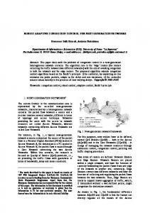
Fig. 1 Upper forward-loop transfer function „circles…, lower forward-loop transfer function „squares…, upper desired forward-loop transfer function „diamonds…, lower desired forward-loop transfer function „triangles…. Note the upper and lower desired forward-loop transfer functions coincide.
less performance variation due to changes in process parameters, as compared to robust controllers without process compensation. The maximum and minimum plant gains, respectively, are ¯P ⫽K ¯ d ¯
(4)
Pគ ⫽K គ d គ
(5)
Next, the desired closed-loop performance bounds are chosen. First-order performance bounds are used in this study. As will be seen, these bounds yield an integral controller that will track constant references and reject constant disturbances. The upper and lower closed-loop performance bounds, respectively, are ¯T 共 s 兲 ⫽
1 ¯ s⫹1
(6)
Tគ 共 s 兲 ⫽
1 គ s⫹1
(7)
The interpretation of the closed-loop performance bounds given by Eqs. 共6兲 and 共7兲 is that the force transient response should be first order with a time constant bounded between ¯ and គ , and the force should track the reference force in the steady state. The upper and lower forward-loop transfer functions 共i.e., the product of the controller and plant transfer functions兲, respectively, to achieve the upper and lower closed-loop performance bounds given in equations 共6兲 and 共7兲, respectively, are ¯L 共 s 兲 ⫽
1 ¯ s
(8)
Lគ 共 s 兲 ⫽
1 គ s
(9)
The Bode plots of the upper and lower forward-loop transfer functions are shown in Fig. 1 for time constants of ¯ ⫽0.3 s and ⫽1.12 s, respectively. Note that the bounds are parallel. As the plant parameters change, the forward-loop transfer function should be bounded by the upper and lower forward-loop transfer functions in Eqs. 共8兲 and 共9兲, respectively. Next, a controller is designed such that the performance bounds are always satisfied as the model and process parameters change within prescribe bounds. In terms of absolute gain, the difference between the maximum and the nominal Bode plant gains is Transactions of the ASME
P U⫽
¯P P nom
(10)
where the nominal plant gain is P nom⫽K nomd  nom
(11)
The Bode gain difference in Eq. 共10兲 is subtracted from the upper forward-loop bound at each frequency. In terms of absolute gains, this is equivalent to dividing the upper forward-loop transfer function by P U . Thus, the desired upper forward-loop transfer function is ¯L d 共 s 兲 ⫽
¯L 共 s 兲 PU
Fig. 2 Block diagram of robust machining force control system
The Bode gain difference in Eq. 共13兲 is added to the lower forward-loop bound at each frequency. In terms of absolute gains, this is equivalent to multiplying the lower forward-loop transfer function by P L . This desired lower forward-loop transfer function is
¯ . The sample period 共see Experimental Results section using d⫽d below兲 is 0.08 s, thus, the upper time constant will be 0.3 s: approximately four times the sample period. Note that the force controller performance is only limited by the hardware limitations of the laboratory mill used for the experiments in this paper. The control method developed here would have superior performance if implemented on a state-of-the-art machine tool. For ¯ ⫽0.3 s, គ will be 1.12 s. Given the range of model and process parameters specified above, this is the tightest performance variation that may be achieved. The transfer functions ¯L d (s) and Lគ d (s) are shown in ¯ . Note that these transfer functions coincide. Fig. 1 for d⫽d When ¯L d (s) and Lគ d (s) coincide
Lគ d 共 s 兲 ⫽Lគ 共 s 兲 P L
¯L d 共 s 兲 ⫽Lគ d 共 s 兲 ⫽ P nomC 共 s 兲
(12)
Similarly, in terms of absolute gain, the difference between the nominal and the minimum Bode plant gains is P L⫽
P nom Pគ
(13)
(14)
The upper and lower desired forward-loop transfer function bounds in Eqs. 共12兲 and 共14兲, respectively, are parallel in a Bode plot since they are each shifted from, respectively, the upper and lower forward-loop bounds, which are parallel, by a constant multiplier. If the magnitude of ¯L d (s) is greater than or equal to Lគ d (s) at every frequency, the closed-loop performance specifications are met. In a Bode plot, this is equivalent to ¯L d (s) being above, or coinciding with, Lគ d (s). Mathematically 1 PL ⫺ ⭓0 P U¯ គ
(15)
Equation 共15兲 may be expressed as ¯
Kd គ ⫺ K  ⭓0
(16)
Equation 共16兲 must be true for all d. The design approach is to select ¯ to be as small as possible given the servomechanism dynamics and then calculate គ by making Eq. 共16兲 an equality and
(17)
Therefore, the controller transfer function may be expressed as C共 s 兲⫽
1 ¯P
¯L 共 s 兲 ⫽
1
1
¯ d ¯ s K ¯
(18)
Note that the controller is an explicit function of the process parameters; in this case, the depth-of-cut. By directly accounting for this process parameter, the developed controller will be able to achieve tighter performance bounds than a robust controller that does not employ process compensation. In this paper, the depthof-cut is the only process parameter that is considered; however, this technique may be applied to other process parameters such as cutting speed and tool wear. To apply this technique to other process parameters, the force process model would need to be modified to include these parameters and their values would need to be either known or measured. The above approach may be used to design a machining force controller if there is no variation in ␣. However, if there is varia-
¯ , ␣ Ä ␣ᠪ ,  Ä ¯ , and Fig. 3 Simulation results. Case I „circles…: robust control with process compensation with K Ä K d Ä d¯ . Case II „squares…: robust control with process compensation with K Ä K ᠪ , ␣Ä␣ ¯ ,  Ä ᠪ , and d Ä d¯ . Case III ¯ , ␣ Ä ␣ᠪ ,  Ä ¯ , and d Ä d¯ . Case IV „triangles…: „diamonds…: robust control without process compensation with K Ä K robust control without process compensation with K Ä K ᠪ , ␣Ä␣ ¯ ,  Ä ᠪ , and d Ä dᠪ . For all cases F r Ä0.285 kN and T Ä0.08 s. Note that the responses for Cases I and III coincide.
Journal of Manufacturing Science and Engineering
AUGUST 2003, Vol. 125 Õ 425
Fig. 4 Simulation results for robust controller with process compensation † d Ä dᠪ „circles…, d Ä d nom „squares…, and d Ä d¯ „diamonds…‡. Simulation parameters: K Ä K nom , ␣ Ä ␣ nom ,  Ä  nom , F r Ä0.285 kN, and T Ä0.08 s.
tion, the controller must be modified to account for the force-feed nonlinearity. If there is a variation in ␣, Eq. 共3兲 may be expressed as F⫽Kd  f ␣ nom共 1⫹ ␦ 兲 ⫽u ␦ Kd  u
(19)
where ␦ represents a deviation from ␣ nom . In this study, the minimum and maximum values of ␦ are ␦គ ⫽⫺0.3 and ¯␦ ⫽0.3, respectively, and the minimum and maximum feeds are គf ⫽0.008 mm and ¯f ⫽0.4 mm, respectively. The term u ␦ may be viewed as an extra factor in the plant gain. Therefore, the controller must be divided by the factor R where R⫽max关u␦兴 to ensure performance robustness for all variations in ␣. For the parameters given above, R⫽2.4. The robust machining force controller with process compensation has the following form C共 s 兲⫽
1 1 1 R ¯P ¯ S
(20)
For the parameters given above, and a continuous to discrete-time conversion performed in Matlab using a pole-zero mapping, the digital controller is C共 z 兲⫽
0.28 1 1 2.4 0.99d 0.85 z⫺1
The block diagram is shown in Fig. 2.
(21)
Robust machining force controllers reported in the literature do not explicitly account for known changes in the force process; thus, larger model parameter variations must be considered and, correspondingly, the resulting performance variation increases. A QFT controller without process compensation can be designed following the method above. However, the depth-of-cut will not be taken into account explicitly and, thus, the controller will not be a function of the depth-of-cut. In this case, the robust controller without process compensation is C共 z 兲⫽
1
1
0.28
2.4 共 0.99兲 d
¯ 0.85
z⫺1
(22)
This controller is identical to the controller in Eq. 共21兲 except that the controller in Eq. 共22兲 is a function of ¯d , not d. Simulation results are shown in Figs. 3–5. Note that cases I and III in Fig. 3 have identical responses. The results in Fig. 3 demonstrate that tighter performance limits may be achieved by explicitly accounting for the process parameters; in this case, the depth-of-cut. The transient performance limits are looser than the specified limits given by គ and ¯ due to the additional factor of R ⫺1 in the controller gain. Simulated responses for the robust controller with process compensation are shown in Fig. 4 for three different depths-of-cut and nominal model parameters. The slight ¯ variation in the responses is due to the factor d  ⫺  that appears in the forward-loop transfer function. There will be maximum varia-
Fig. 5 Simulation results for robust controller without process compensation † d Ä dᠪ „circles…, d Ä d nom „squares…, and d Ä d¯ „diamonds…‡. Simulation parameters: K Ä K nom , ␣ Ä ␣ nom ,  Ä  nom , F r Ä0.285 kN, and T Ä0.08 s.
426 Õ Vol. 125, AUGUST 2003
Transactions of the ASME
Fig. 6 Schematic of experimental system and part. The part is fed towards the tool in the negative x direction.
tion in response when  ⫽ គ and no variation when  ⫽ ¯ . Simulated responses for the robust controller without process compensation are shown in Fig. 5 for three different depths-of-cut and nominal model parameters. A comparison of the results in Figs. 4 and 5 demonstrates that explicitly accounting for process variations allows the proposed controller to maintain a relatively constant response in the face of known process parameter variations.
Experimental Results Experiments are conducted for a face milling operation to verify the proposed robust control design and compare robust machining force controllers with process compensation to those without process compensation. A schematic of the experimental system is shown in Fig. 6. While this system is not an industrialgrade machine tool, it provides an adequate platform to illustrate the novel properties of the proposed controller and to compare it to traditional robust controllers. The objective of the force control system is to maintain maximum productivity given a spindle
power constraint. With a constant spindle speed of 1500 rpm, a maximum spindle power of 1.5 hp, and a tool radius of 25 mm, the maximum cutting force is 0.285 kN. The force signal that will be regulated is F⫽max关 兩 f 1y 兩 , . . . , 兩 f Ny 兩 兴
(23)
where f y is the instantaneous force in the y direction and N is the number of samples during two spindle rotations. This signal processing will mitigate the effect of runout. The force signal in Eq. 共23兲 bounds the cutting force 关14兴. A sample period of 0.5 ms is used to collect the individual force samples 共i.e., f 1y , . . . , f Ny ), thus, N⫽160 and the force controller sample period is 0.08 s. The tool engages the part for a period of time at a low feed before the controller is activated; thus, the force in the experiments always starts at some positive value. The force sensor is a Kistler 9293 piezoelectric four-component dynamometer with a bandwidth of approximately 4500 Hz. The linear axes are connected to the PC controller via analog to digital
¯ , ␣ Ä ␣ᠪ , Fig. 7 Experimental results for robust controller with process compensation. Controller parameters: K Ä K  Ä ¯ , d Ä dᠪ , F r Ä0.285 kN, and T Ä0.08 s.
Journal of Manufacturing Science and Engineering
AUGUST 2003, Vol. 125 Õ 427
Fig. 8 Experimental results for robust controller with process compensation. Controller parameters: K Ä K ᠪ , ␣ Ä ␣¯ ,  Ä ᠪ , d Ä d¯ , F r Ä0.285 kN, and T Ä0.08 s.
共12 bit兲, digital to analog 共8 bit兲, and counter timer boards. The axis command voltages are sent via the digital to analog boards to pulse width modulators that drive the motors. The axis tachometers and table encoders 共10 m resolution兲 send information to the controller via the analog to digital and counter timer boards, respectively. The closed-loop servomechanisms have bandwidths of approximately 40 Hz. Since the sensor and actuator dynamics are much faster than the force process dynamics, they are not considered in the model. In order to verify the controller performance robustness to parameter variations, the controller was intentionally designed for non-nominal parameter values to mimic parameter variations. Two experiments were conducted: one with d⫽dគ , ␣ ⫽ ␣គ  ⫽ ¯ , ¯ , and another with d⫽d ¯ , ␣ ⫽ ¯␣ ,  ⫽ គ , and K⫽K and K⫽K គ . The results are shown in Figs. 7 and 8, respectively. The settling time in Fig. 7 is faster than predicted; however, the response is overdamped, as expected. The performance in Fig. 8 is very similar to case II in Fig. 3. The response is much noisier in Fig. 8 than Fig. 7 since small variations in feed create greater force fluctuations when the depth-of-cut is larger 共6 mm as compared to 1 mm兲. Another set of experiments was conducted to verify the control-
ler performance robustness to parameter variations where a single model parameter was varied to its minimum or maximum value while the other model parameters were held at their nominal values. In each test, d⫽3 mm. For the results shown in Figs. 9–12, ¯ , respectively, while the other ␣ ⫽ ␣គ , ␣ ⫽ ¯␣ , K⫽Kគ , and K⫽K variables were held at their nominal values. The simulated responses match the experimental responses quite well. In the next experiment, the robust machining force controller with process compensation is used to machine a part whose depthof-cut changes from 1 mm to 3 mm and then to 5 mm. The results are shown in Fig. 13. The transient performance does not change significantly for different depths-of-cut. Further, the transient performance is very similar to that in the simulations 共see Fig. 4兲. Next, the robust machining force controller without process compensation is employed for an operation with two different depthsof-cut 共1 mm and 5 mm兲. The results, shown in Fig. 14, demonstrate how the transient performance changes dramatically for different depths-of-cut. This illustrates the advantage of taking the depth-of-cut explicitly into account in the controller design. Note that in Figs. 13 and 14, the large peaks are due to the sudden change in the depth-of-cut, and not controller overshoot. These sudden changes are outside the bandwidth of machine tool servomechanism systems and, thus, are unavoidable. Also, there
Fig. 9 Experimental „circles… and simulation „squares… results for robust controller with process compensation. Simulation parameters: K Ä K nom , ␣ Ä ␣ ᠪ ,  Ä  nom , d Ä3 mm, F r Ä0.285 kN, and T Ä0.08 s.
Fig. 10 Experimental „circles… and simulation „squares… results for robust controller with process compensation. Simulation parameters: K Ä K nom , ␣ Ä ␣ ¯ ,  Ä  nom , d Ä3 mm, F r Ä0.285 kN, and T Ä0.08 s.
428 Õ Vol. 125, AUGUST 2003
Transactions of the ASME
Fig. 11 Experimental „circles… and simulation „squares… results for robust controller with process compensation. Simulation parameters: K Ä K ᠪ , ␣ Ä ␣ nom ,  Ä  nom , d Ä3 mm, F r Ä0.285 kN, and T Ä0.08 s.
are force variations about the reference force in the experimental implementations. These variations are due to the limited resolution of the digital to analog converter 共8 bit兲, structural vibrations, and, in some cases, chip interference.
Summary and Conclusions A novel robust machining force controller, based on QFT, has been developed in this paper. The proposed controller is the first robust controller to explicitly account for known process changes 共e.g., changes in the depth-of-cut兲 and for the force-feed nonlinearity inherent in metal cutting operations. The performance of the developed controller was verified via simulations and experiments, and the results were compared to a robust machining force controller without process compensation. The robust machining controller developed in this paper is based on a simple design procedure. No iterations are required, unlike most QFT designs. Thus, the controller can be updated on-line as information regarding the range of parameter variations becomes available. The controller design is based on a static model where the force process rise time is assumed to be much slower than the servo system rise time. This has been verified to be a valid assumption based on experimental results 关7兴 and will
Fig. 12 Experimental „circles… and simulation „squares… results for robust controller with process compensation. Param¯ , ␣ Ä ␣ nom ,  Ä  nom , d Ä3 mm, F r Ä0.285 kN, and eters: K Ä K T Ä0.08 s.
Journal of Manufacturing Science and Engineering
Fig. 13 Experimental results for proposed robust controller with process compensation. Parameters: K Ä K nom , ␣ Ä ␣ nom ,  Ä  nom , F r Ä0.285 kN, and T Ä0.08 s.
be applicable to many machining operations where the force signal must be processed every spindle revolution 共e.g., general milling applications兲. The robust machining force controller design was verified through a variety of simulation and experimental studies. Further, this novel controller explicitly accounts for known or measurable changes in the process. Therefore, the controller is able to maintain tighter performance bounds than a controller that does not include process compensation and the performance will not be significantly affected as the process changes. In this study, known changes in the depth-of-cut were explored. To incorporate other process parameters 共e.g., cutting velocity, tool wear兲, the force process model would need to be augmented and these parameters would need to be known or measured. With the advent of open-architecture software platforms for machining controllers, the way is being paved for the implementation of force control technology. It should be noted that the proposed controller, like all machining force controllers, is not applicable for all production situations. For a job-shop environment where the tools, parts, and cutting fluid combinations change with every order, adaptive techniques would be appropriate. For a highvolume environment where the operating characteristics are constant and, thus, accurate models may be cost-effectively obtained, a model-based controller tuned to the specific situation would be appropriate. For a batch production environment with a specific
Fig. 14 Experimental results for robust controller without process compensation. Parameters: K Ä K nom , ␣ Ä ␣ nom ,  Ä  nom , F r Ä0.285 kN, and T Ä0.08 s.
AUGUST 2003, Vol. 125 Õ 429
range of operating characteristics, robust techniques that are not as complex as adaptive techniques, but are guaranteed to account for parameter variations, would be appropriate. The proposed robust controller also allows for tight performance bounds as compared to traditional robust control techniques since it directly compensates for known process changes.
Acknowledgment The authors gratefully acknowledge the financial support of the University of Michigan’s Engineering Research Center for Reconfigurable Machining Systems 共NSF Grant #EEC 9529125兲.
Nomenclature depth-of-cut 共mm兲 feed 共mm/tooth兲 machining force 共kN兲 reference machining force 共kN兲 cutting coefficient 共kN/mm2兲 K nom nominal value of cutting coefficient 共kN/mm2兲 Kគ minimum value of cutting coefficient 共kN/mm2兲 ¯ K maximum value of cutting coefficient 共kN/mm2兲 t time 共s兲 ␣ feed exponent in force relationship ␣ nom nominal value of feed exponent in force relationship  depth exponent in force relationship  nom nominal value of depth exponent in force relationship គ minimum value of depth exponent in force relationship ¯ ⫽ maximum value of depth exponent in force relationship គ ⫽ desired time constant for lower closed-loop transfer function bound 共s兲 ¯ ⫽ desired time constant for upper closed-loop transfer function bound 共s兲 d f F Fr K
⫽ ⫽ ⫽ ⫽ ⫽ ⫽ ⫽ ⫽ ⫽ ⫽ ⫽ ⫽ ⫽ ⫽
430 Õ Vol. 125, AUGUST 2003
References 关1兴 Jeppsson, J., 1988, ‘‘Adaptive Control of Milling Machines,’’ SME Technical Paper MS88-103, Advanced Machining Technology II, Phoenix, AZ, Feb. 16 – 18. 关2兴 Ulsoy, A. G., Koren, Y., and Rasmussen, F., 1983, ‘‘Principle Developments in the Adaptive Control of Machine Tools,’’ ASME J. Dyn. Syst., Meas., Control, 105共2兲, pp. 107–112. 关3兴 Lauderbaugh, L. K., and Ulsoy, A. G., 1989, ‘‘Model Reference Adaptive Force Control in Milling,’’ ASME J. Eng. Ind., 111共1兲, pp. 13–21. 关4兴 Altintas, Y., 1994, ‘‘Direct Adaptive Control of End Milling Process,’’ Int. J. Mach. Tools Manuf., 34共4兲, pp. 461– 472. 关5兴 Harder, L., 1995, ‘‘Cutting Force Control in Turning—Solutions and Possibilities,’’ Ph.D. Dissertation, Department of Materials Processing, Royal Institute of Technology, Stockholm. 关6兴 Landers, R. G., and Ulsoy, A. G., 1996, ‘‘Machining Force Control Including Static, Nonlinear Effects,’’ Japan USA Symposium on Flexible Automation, Boston, Massachusetts, July 8 –10, pp. 983–990. 关7兴 Landers, R. G., and Ulsoy, A. G., 2000, ‘‘Model-Based Machining Force Control,’’ ASME J. Dyn. Syst., Meas., Control, 122共3兲, pp. 521–527. 关8兴 Chen, B-S., and Chang, Y-F., 1991, ‘‘Robust PI Controller Design for A Constant Turning Force System,’’ Int. J. Mach. Tools Manuf., 31共3兲, pp. 257–272. 关9兴 Carrillo, F. J., Rotella, F., and Zadshakoyan, M., 1999, ‘‘Delta Approach Robust Controller for Constant Turning Force Regulation,’’ Control Eng. Pract., 7共11兲, pp. 1321–1331. 关10兴 Hayes, R. D., Shin, Y. C., and Nwokah, O. D. I., 1993, ‘‘Robust Control Design for Milling Processes,’’ DSC-Vol. 50/PED-Vol. 63, ASME Winter Annual Meeting, New Orleans, LA, Dec., pp. 119–125. 关11兴 Punyko, A. J., and Bailey, F. N., 1994, ‘‘A Delta Transform Approach to Loop Gain-Phase Shaping Design of Robust Digital Control Systems,’’ Int. J. Robust Nonlinear Control, 4共1兲, pp. 65– 86. 关12兴 Nordgren, R. E., and Nwokah, O., 1994, ‘‘Parametric and Unstructured Uncertainty Models in Discrete Time Systems,’’ DSC Vol. 55-1, ASME Winter Annual Meeting, Chicago, IL, Nov. 6 –11. 关13兴 Rober, S. J., Shin, Y. C., and Nwokah, O. D. I., 1997, ‘‘A Digital Robust Controller for Cutting Force Control in the End Milling Process,’’ ASME J. Dyn. Syst., Meas., Control, 119共2兲, pp. 146 –152. 关14兴 Landers, R. G., 1997, ‘‘Supervisory Machining Control: A Design Approach Plus Force Control and Chatter Analysis Components,’’ Ph.D. Dissertation, Department of Mechanical Engineering, University of Michigan, Ann Arbor, Michigan.
Transactions of the ASME