J. Cent. South Univ. (2014) 21: 3777−3786 DOI: 10.1007/s11771-014-2362-0
Robust PID controller design for time delay processes with peak of maximum sensitivity criteria Mohammad Shamsuzzoha Department of Chemical Engineering, King Fahd University of Petroleum and Minerals, Dhahran 31261, Saudi Arabia © Central South University Press and Springer-Verlag Berlin Heidelberg 2014 Abstract: The motivation of this work is to obtain single PI/PID tuning formula for different types of processes with enhanced disturbance rejection performance. The proposed tuning formula consistently gives better performance in comparison to several well-known methods at the same degree of robustness for stable, integrating and unstable processes. For the selection of the closed-loop time constant (τc), a guideline is provided over a broad range of time-delay/time-constant ratios on the basis of the peak of maximum sensitivity (Ms). An analysis has been performed for the uncertainty margin with the different process parameters for the robust controller design. It gives the guideline of the Ms-value settings for the PI controller designs based on the process parameters uncertainty. Furthermore, a relationship has been developed between Ms-value and uncertainty margin with the different process parameters (k, τ and θ). Simulation study has been conducted for the broad class of processes and the controllers are tuned to have the same degree of robustness by measuring the maximum sensitivity, Ms, in order to obtain a reasonable comparison. Key words: PI/PID controller tuning; internal model control (IMC) method; unstable delay process; integrating delay process; disturbance rejection
1 Introduction The proportional integral derivative (PID) controller is the most widely used control algorithm for regulatory control layer in process industries. It is because of their simplicity, ease of implementation, robustness and wide ranges of applicability with near-optimal performance. The stable and integrating processes are very common in process industries in flow, level and temperature loop. The open-loop unstable processes are also encountered in chemical processing units and known to be difficult to control, especially when there exists a time delay, such as in the case of continuous stirred tank reactors, polymerization reactors and bioreactors which are sometimes open-loop unstable by design. A recent survey of KANO and OGAWA [1] shows that the ratio of applications of different types of controller, e.g., PI control, conventional advanced control and model predictive control is about 100:10:1. There is no perfect alternative of the PID controller at least at the bottom layer in the process industries. This was the clear conclusion at the end of the IFAC Conference on Advances in PID Control, held in Brescia (Italy) during 28−30 March, 2012. Although the PID controller has only three adjustable parameters, it is not easy to get suitable controller settings without a systematic
procedure. Due to this reason, a large number of PID controllers are poorly tuned in industries. There are variety of controller tuning approaches reported in the literature and among that two types are widely used, one may use open-loop or closed-loop plant test. Most tuning approaches are based on open-loop plant information; typically the plant’s gain (k), time constant (τ) and time delay (θ). The effectiveness of the internal model control (IMC) design principle has made it attractive in the process industries, where many attempts have been made to exploit the IMC principle to design PI/PID controllers for both stable and unstable processes. The IMC-PID tuning rules have the advantage of using only a single tuning parameter to achieve a clear trade-off between the closed-loop performance and robustness. The PI/PID tuning methods proposed by RIVERA et al [2], LEE et al [3], SKOGESTAD [4] and SHAMSUZZOHA and LEE [5], are typical examples of the IMC-PID tuning method. The direct synthesis (DS) method [6] and the direct synthesis for the disturbance (DS-d) method proposed by CHEN and SEBORG [7] can also be categorized into the same class as the IMC-PID methods, in that they obtain the PI/PID controller parameters by computing the ideal feedback controller which gives a predefined desired closed-loop response. Although the ideal controller is often more complicated than the PI/PID
Received date: 2013−12−30; Accepted date: 2014−05−29 Corresponding author: Mohammad Shamsuzzoha, Assistant Professor, PhD; Tel: +966−138607360; E-mail:
[email protected]
3778
controller for time delayed processes, the controller form can be reduced to that of either a PI/PID controller or a PID controller cascaded with a low order filter by performing appropriate approximations of the dead time in the process model. It is essential to emphasize that the PI/PID controller designed according to the IMC principle provides excellent set-point tracking, but has a sluggish disturbance response, especially for processes with a small time-delay/time-constant ratio [2−5, 8]. In process industries, disturbance rejection is much more important than set-point tracking for many process control applications, a controller design that emphasizes the former rather than the latter is an important design problem and it has been the focus of the research. It is well known that the IMC structure is very powerful for controlling stable processes with time delay and cannot be directly used for unstable processes because of the internal instability [8]. For this reason, some modified IMC methods of two-degree-of-freedom (2DOF) control were developed for controlling unstable processes with time delay, such as those proposed by LEE et al [9], YANG et al [10], WANG and CAI [11], TAN et al [12], LIU et al [13] and JUNG et al [14]. In addition, 2DOF control methods based on the Smith-Predictor (SP) were proposed by MAJHI and ATHERTON [15], KWAK et al [16], and ZHANGE et al [17] to achieve a smooth nominal setpoint response without overshoot for first order unstable processes with time delay. The delay integrating process is very important in process industries. It has a clear advantage in the identification test, because the model contains only two parameters and is simple to use for identification. Some of the well accepted PI/PID controllers tuning methods for delay integrating processes are those proposed by SKOGESTAD [4], CHEN and SEBORG [7] and TYRUS and LUBYEN [18], SHAMSUZZOHA and LEE [19]. ALCANTARA et al [20] have addressed the model-based tuning of the PI/PID controller based on the robustness/performance and servo/regulator trade-offs. K-SIMC method, a modification of SIMC rule has been proposed by LEE et al [21] for stable process and subsequently for unstable process [22]. TORRICO et al [23] proposed a new and simple design for the filtered Smith predictor (FSP), which belongs to a class of dead-time compensators (DTCs) and allows the handling of stable, unstable, and integrating processes. ALFARO and VILANOVA [24] have proposed unified simple optimal and robust tuning (uSORT1) method. It is 1DOF PI/PID controller tuning method for the FOPDT and SOPDT process. The uSORT1 method allows to adjust the control system robustness varying only the controller gain. JIN and LIU [25] proposed IMC-PI tuning rules
J. Cent. South Univ. (2014) 21: 3777−3786
based on model matching approach and closed-loop shaping. Subsequently, JIN and LIU [26] suggested analytical tuning rules of 2-Degree of freedom PID controller for integrating processes, which was based on an enhanced IMC principle for IPTD, IFOPTD and DIPTD models with robustness/performance criteria. JENG and LIN [27] proposed robust PID tuning for stable/integrating processes with inverse response and time delay. Their design method is based on a Smith-type compensator for nonminimum phase dynamics. Based on the optimization problem, ARRIETA and VILANOVA [28] addressed the combined servo/regulation performance and robustness problem for PID controller tuning. A unified approach was proposed by NORMEY-RICO and GUZMÁN [29], which is based on a PID approximation of the filtered Smith predictor, for tuning PID controllers for stable, integrating, and unstable dead-time processes. The main alternative of the above mentioned open-loop approach is to use closed-loop experiments. One approach is the classical method of Ziegler-Nichols [30] which requires very little information about the process to obtain controller setting. Recently, several authors [31−33] have proposed modified tuning methods based on closed-loop experiments and resulting controller gives better performance. The recent published online controller tuning method in closed-loop mode by SHAMSUZZOHA [33] overcomes the shortcoming of the well-known Ziegler-Nichols continuous cycling method and gives consistently better performance and robustness for a broad class of processes. It should be emphasized that the design principle of the most of the aforementioned tuning methods is complicated and that the modified IMC structure for unstable process is difficult to implement in a real process plant in the presence of model uncertainty. Therefore, in this work, a simple analytical method is proposed for the design of the PI/PID controller. Overcoming the drawback of other tuning rules for different types of processes, only single tuning rule is capable to handle different types of processes with performance improvement. A τc guideline was recommended for a wide range of time-delay/timeconstant ratios (θ/τ). A guideline of the Ms-value settings has been also proposed based on the process parameters uncertainty (k, τ and θ) margin. Simulation study was performed to show the validity of the proposed method at same Ms-value.
2 Theory of IMC-PID controller design Figures 1(a) and (b) show the block diagrams of the IMC control and equivalent classical feedback control structures, respectively, where Gp is the process, G p is
J. Cent. South Univ. (2014) 21: 3777−3786
3779
the process model, q is the IMC controller, fr is the set-point filter, and Gc is the equivalent feedback controller.
Then, the IMC controller comes to be m
q pm1
( i s i 1) i 1
(5)
( c s 1) r
Thus, the resulting set-point and disturbance responses are obtained as m
i si 1
Fig. 1 Block diagram of IMC and classical feedback control systems: (a) IMC structure; (b) Feedback control structure
For the nominal case Gp G p , the set-point and disturbance responses in the IMC control structure can be simplified as y Gp qf r r (1 G p q)Gp d (1) According to the IMC parameterization [2], the process model G p is factored into two parts: G p pm pA (2) where pm is the portion of the model inverted by the controller, pA is the portion of the model not inverted by the controller and pA(0)=1. The noninvertible part usually includes the dead time and/or right half plane zeros and is chosen to be all-pass. To get a superior response for unstable processes or stable processes with poles near zero, the IMC controller q should satisfy following conditions. If the process Gp has unstable poles or poles near zero at z1, z2,…, zm, then q should have zeroes at z1, z2,…, zm, and (1−Gpq) should also have zeroes at z1, z2,…, zm. Since the IMC controller q is designed as q pm1 f , the first condition is satisfied automatically. The second condition can be fulfilled by designing the IMC filter (f) as f
im1 i s i 1 ( c s 1) r
(3)
where τc is an adjustable parameter which controls the tradeoff between the performance and robustness; r is selected to be large enough to make the IMC controller (semi-)proper; αi is determined by Eq. (4) to cancel the poles near zero in Gp.
1 Gp q
s z1 , zm
1
pA (im1 i s i 1) ( c s 1) r sz
1
0 ,, zm
(4)
y Gp qf r pA i 1 fr r ( c s 1) r
(6)
m i si 1 y G (1 Gp q )Gp 1 pA i 1 p d ( c s 1) r
(7)
The numerator expression
m
i si 1
in Eq. (6)
i 1
causes an excessive overshoot in the servo response, which can be eliminated by introducing the set-point filter fr to compensate for the overshoot in the servo response. From the above design procedure, a stable, closed-loop response can be achieved by using the IMC controller. The ideal feedback controller that is equivalent to the IMC controller can be expressed in terms of the internal model G p and the IMC controller q as: Gc
q 1 G p q
(8)
Substituting Eqs. (2) and (5) into Eq. (8) gives the ideal feedback controller: m
pm1 Gc
( i s i 1) i 1
( c s 1) r m
1
pA ( i s 1)
(9)
i
i 1
( c s 1) r
The resulting controller in Eq. (9) is physically realizable but it does not have the standard PI/PID form. The desired form of the controller can be obtained by using the proper approximation of the dead time term for example Taylor series expansion. In this work, both simplicity and approximation error due to dead time term has been considered carefully during the PI/PID controller design.
3 PI/PID controller design This section illustrates the PI/PID controller design method for several representative cases which are
J. Cent. South Univ. (2014) 21: 3777−3786
3780
frequently used by the process control engineer in real processes. 3.1 First-order plus dead time process First order plus dead time (FOPDT) process is representative model and commonly used in the chemical process industries.
Gp
ke s s 1
(10)
where k is the process gain, τ is the time constant, and θ is the time delay, the IMC filter structure selected is f
s 1 ( c s 1) 2
(11)
process becomes the series-form of the controller as 1 Ds 1 Gc K c 1 Is D N s 1
(17)
where τD is the derivative time. In the simulation study, filter parameter N is typically around 100 and can be utilized to make the series-PID controller with derivative filter. The implementation of the series-PID structure in Eq. (17) is shown in Fig. 2. In the simulation of the second order process, the robustness margins have been computed with τD/N=0. The PID setting of the proposed method is for the series form of the PID controller. If required, it can be easily converted to the ideal (parallel) form of the PID.
After utilizing the above IMC design principle the ideal feedback controller is given as Gc
( s 1)( s 1) k ( c s 1) 2 e s ( s 1)
(12)
From Eq. (12), the resulting PI controller can be obtained using Taylor series expansion, e−θs=1−θs and then simplified as Kc
k (2 c )
; I
(13)
Furthermore, it is obvious that the remaining part of the denominator in Eq. (12) contains the factor of the process poles (τs+1). It has been ignored because of its little impact on the control performance, while keeping the simple PI control structure. The value of α is selected so that it cancels out the pole at s=−1/τ. From Eq. (4), this requires [1−(αs+1)e−θs/ (τcs+1)2]s=−1/τ and the value of α is obtained as
c e 2
1 1
(14)
3.2 Second-order plus dead time process Consider a stable second-order plus dead time (SOPDT) process as Gp
ke s ( s 1)( 2 s 1)
(15)
The recommended controller setting for the SOPDT process is PID. It is mainly recommended for the “dominant” second-order process. It means that the second-order time constant (τ2) is larger than the effective time delay θ, i.e., τ2>θ. Based on the IMC design principle, the PID controller setting for the SOPDT process is given as
Kc
k (2 c )
; I ; D 2
(16)
The proposed PID controller setting for the SOPDT
Fig. 2 Cascade implementation of PID controller without differentiation of setpoint
Here, we should note the follows. First-order delayed unstable process (FODUP) does not have the form of Eq. (10). It can be easily transformed to the form of Eq. (10) by adjusting their sign for PI controller design, e.g., for the FODUP -k and -τ. Similar concept is also applicable for the second order unstable process with time delay. The delayed integrating process (DIP) can be modeled by considering the integrator as a stable pole near zero. This is mandatory since it is not practicable to implement the aforementioned IMC based design procedure for the DIP, because the term, α, vanishes at s=0. As a result, the DIP can be approximated to the FOPDT as Gp
ke s ke s ke s s s 1/ s 1
(18)
where ψ is a constant with a sufficiently large value, e.g., ψ=100. Accordingly, the optimum IMC filter structure for the DIP is identical to that of the FOPDT and resulting PI parameters is same as FOPDT. 3.3 Setpoint filter to enhance servo response In the proposed controller design, term (αs+1) shows a large overshoot for the step set-point change, it is because the controller is designed based on the disturbance rejection. Therefore, a set-point filter fr is suggested to remove excessive overshoot and enhance the servo response. s 1 (19) fr c ( s 1)
J. Cent. South Univ. (2014) 21: 3777−3786
3781
TAN et al [12] also suggested this form of set-point filter. Due to this type of lead-lag filter, resulting response will be first order with the time constant of τc for the set-point change.
4 Simulation study Although the simulation study is conducted on the different types of processes, only few of them are discussed below. The proposed tuning rule provides acceptable controller settings in all cases with respect to both performance and robustness. The closed-loop performance is evaluated by introducing a unit step change in both the set-point and load disturbance, i.e., (ys=1 and d=1). The brief overview of the performance and robustness measure is mentioned below. Output performance (y) is quantified by computing the integrated absolute error, EIA =
0
y y s dt .
Manipulated variable usage is quantified by calculating the total variation (VT) of the input (u), which is the sum of all its moves up and down. If input signal is discretized as a sequence [u1, u2, u3…, ui…], then
VT = ui +1 ui . Note also that VT is the integral of the i=1
absolute value of the derivative of the input, du VT = dt , so V T is a good measure of the 0 dt smoothness. To evaluate the robustness, maximum closed-loop sensitivity is computed in the present work which is defined as Ms=maxω|1/[1+gc(jω)]. Since Ms is
the inverse of the shortest distance from the Nyquist curve of the loop transfer function to the critical point (−1, 0), a small Ms-value indicates that the control system has a large stability margin. It is better to have EIA, VT and Ms all to be small, but for a well-tuned controller there is a trade-off, which means that a reduction in EIA implies an increase in VT and Ms, (and vice versa). To achieve the fair comparisons in the simulation study, all controllers have been tuned by adjusting τc for the same degree of robustness by fixing Ms. The results of five different types of processes with performance and robustness matrix are listed in Table 1. Figures 3−7 show comparison of the proposed method with other methods like SIMC [4], DCLR [3] and TL [18]. In case of stable and integrating process proposed method gives faster disturbance rejection and has clear advantage over the DCLR and SIMC methods. The proposed method also works well in first and second order unstable processes with dead time. The results of examples C4 clearly show that the proposed method gives both smaller overshoot and faster disturbance rejection while maintaining setpoint performance for unstable process. From above analysis, it seems that the proposed method constantly gives better closed-loop response for several types of processes at same Ms-value compared with other methods. For the PI-controller design, delay integrating process (DIP) should be approximated to the FOPDT process. In the present simulation case, C2 has been modeled as 20e−7.4s/(100s+1).
Table 1 PI/PID controller setting for proposed and other methods with performance matrix Case
Process
C1
e s 10s 1
C2
C3
0.2e7.4s s e 0.5 s s 1 0.5 s
C4
e (5s 1)(2 s 1)(0.5s 1)
C5
10e s (20 s 1)(20 s 1)
Method
τc
Ms
Kc
τI
Setpoint EIA: (y)
VT
Proposed
2.46
1.60
4.57
4.85
3.1
SIMC
1.0
1.60
5.0
8.0
LEE et al [3]
1.0
1.60
5.12
Proposed
19.37
1.70
SIMC
7.4
TL
Load disturbance EIA (y)
VT
5.9
1.06
1.37
2.5
5.6
1.60
1.16
10.25
2.17
5.58
2.0
1.10
0.304
39.63
30.21
0.51
131.9
1.74
1.70
0.338
59.2
28.8
0.49
174.5
1.55
—
1.67
0.33
64.7
29.13
0.46
195
1.50
Proposed
1.36
6.0
1.646
8.25
6.72
12.0
5.01
7.30
LEE et al [9]
1.4
6.0
1.668
8.67
6.77
12.04
5.20
7.24
Proposed
2.9
2.2
3.22
9.50
6.37
7.59
2.95
2.59
YANG et al [10]
1.5
2.2
2.564
10.98
8.57
7.24
4.28
2.95
Proposed
2.57
1.65
0.942
5.55
20.39
1.48
5.89
2.44
SIMC
1.0
1.65
1.0
8.0
20.6
1.44
8.0
2.44
Note: For case C4, τD=2.25 and 1.82 is used for proposed and YANG et al [10] methods, respectively; For case C5, τD=20 is used for both proposed and SIMC methods, response is without setpoint filter for both the methods. A set-point filter fr is suggested to enhance servo response, for PI controller f r ( c s 1) /( s 1); for PID f r ( c s 1) /( 2 s 2 s 1).
3782
J. Cent. South Univ. (2014) 21: 3777−3786
Fig. 3 Responses of PI-control of first-order process Gp= e−s/(10s+1) (C1) for both setpoint (a) and load disturbance (b) of magnitude 1 at t=0
Figure 6 shows the manipulated variable (MV) response for C1 as the representative case. The response of the MV of the proposed method is comparable with the SIMC [4] and LEE et al [3]. 4.1 Proposed method for dominant second order processes A published SOPDT model [20] which has τ1≈τ2 was considered for the performance comparison as
C5 (SOPDT): Gp
10e s (20 s 1)(20 s 1)
(20)
The proposed method has been compared with the SIMC method for C5. The SIMC parameters of the PID-series controller settings has been obtained for τc=θ=1, which gives Ms=1.65. In order to ensure a fair comparison, the proposed PID setting is tuned to have same Ms=1.65 by adjusting their closed loop time constant, τc=2.57. To compare the response, a unit step change is introduced in both the set-point and load disturbance. Figure 7 compares the set-point and load disturbance responses obtained using both the compared controllers. The closed loop response for setpoint change
Fig. 4 Responses of PI-control of integrating process Gp=0.2e−7.4s/s (C2) for both setpoint (a) and load disturbance (b) of magnitude 1 at t=0
for both the proposed and SIMC method are almost identical, while there is significant advantage of the proposed method in disturbance rejection where it shows smaller overshoot and fast settling time. 4.2 Effect of setpoint filter on servo response The proposed method is based on the disturbance rejection so the large overshoot for the step setpoint change can occur particularly for the unstable and integrating processes. Therefore, lead-lag set-point filter is recommended to remove the overshoot in setpoint response. To show the performance improvement, a firstorder unstable process with time delay (Case C3) has been considered. The resulting set-point filter of the proposed study for C3 should be fr=(1.36s+1)/(8.25s+1). Figure 8 shows the closed-loop response of the proposed method for both with and without set-point filter where EIA is reduced from 6.72 to 1.90. As expected the output response with set-point filter is fast without any overshoot.
5 Discussion In the proposed tuning rule, the closed-loop time constant τc controls the tradeoff between robustness and
J. Cent. South Univ. (2014) 21: 3777−3786
3783
Fig. 5 Responses of PID-control for high order unstable process Gp=e−0.5s/(5s−1)(2s+1)(0.5s+1) (C4) for both setpoint (a) and load disturbance (b) of magnitude 1 at t=0
Fig. 6 MV plots of PI-control for first-order process e−s/(10s+1) (C1) for both setpoint (a) and load disturbance (b) of magnitude 1 at t=0
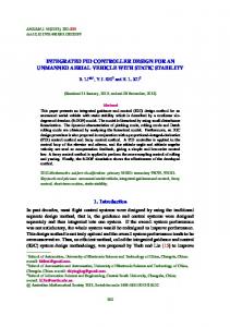
performance of the control system. As τc decreases, the closed-loop response becomes faster and can be unstable. On the other hand, as τc increases, the closed-loop response becomes sluggish and more stable. A good tradeoff is obtained by choosing τc to give Ms-value in the range of 1.2−2.0 for stable process. An analysis of the τc selection has been conducted and plot of Ms verses θ/τ for different values of τc= γθ, where γ=1.0, 2.0 and 3.0 is shown in Fig. 9. The figure clearly shows that τc=θ is not the proper choice because for the lag dominant process, it gives tight controller setting. For τc=3θ, it gives smooth and robust setting because Ms lies between 1.61 to 1.25. A good tradeoff between robustness and performance can be achieved for τc=2θ where it gives Ms=2.0 for lag dominant process and Ms=1.26 for delay dominant process.
is important to obtain the relationship between Ms-value and parametric uncertainty in the control system design. It is because these uncertainties play an important role in control system and cause poor performance or even instability of closed-loop control systems. A typical first order delay process (e−θs/(10s+1)) is considered for this analysis for various dead time to lag time ratios by changing θ while fixing τ=10). The Kharitonov’s theorem is used to obtain the uncertainty margin in the process parameter and further it is verified by the simulation for different θ/τ ratio. The percentages of the uncertainty margin in different parameters have been analyzed for different Ms-value. Figure 10 shows the variation in dead time margin for different Ms-values. The figure clearly indicates that for a fixed Ms-value, as the θ/τ ratio increases, the dead time margin also increases. The variation in the process gain uncertainty for the different Ms-values is shown in Fig. 11. The trend in Fig. 11 is reverse and it shows that for the fixed Ms-value, as θ/τ ratio increases, the percentage in the gain margin decreases. The uncertainty in the process time constant τ is shown in Fig. 12. The uncertainty margin in the τ is lower than the original value whereas
6 Robustness study This section presents the analysis of the control system design for system affected by parametric uncertainty. It indicates the maximum uncertainty margin in different process parameters for the fixed Ms-value. It
3784
J. Cent. South Univ. (2014) 21: 3777−3786
Fig. 9 τc guidelines of first order stable process with time delay based on time delay in process
Fig. 7 Responses of PID-control of second-order process
Gp=
10e s (C5) for both setpoint (a) and load (20 s 1)(20 s 1)
disturbance (b) of magnitude 1 at t=0
Fig. 8 Effect of setpoint filter to remove overshoot from setpoint response: Setpoint responses of PI-control of firstorder unstable process with time delay Gp=e−0.5s/(s−1) (C3) for both setpoint and load disturbance of magnitude 1 at t=0
in the k and θ is higher than original values. These combinations have deteriorating impact on the control system performance. The maximum tolerance limit for
Fig. 10 Variation of uncertainty margin in time delay (θ) with θ/τ ratio for different Ms-values
Fig. 11 Variation of uncertainty margin in process gain (k) with θ/τ ratio for different Ms-values
wide range of θ/τ ratio of the uncertainty in different process parameters (k, θ and τ) is given in the Table 2. Based on this information, one can select the suitable Ms-value for safe PI controller design of the uncertain process. The other PI tuning methods have almost similar combinations of the uncertainly margin for fixed Ms-value.
3785
J. Cent. South Univ. (2014) 21: 3777−3786
time constant is τc=2θ for a wide range of θ/τ ratio. 7) The guideline of the Ms-value is given for the PI controller design of the uncertain process. The proposed investigation of the Ms-value verses uncertainty margin in the process parameter can be very useful for the robust controller design. 8) Several important representative processes are considered in the simulation study in order to demonstrate the advantage of the proposed method. In particular, the proposed controller shows excellent performance when the lag time dominates.
Acknowledgement Fig. 12 Variation of uncertainty margin in process time constant (τ) with θ/τ ratio for different Ms-values Table 2 Maximum uncertainty margin in θ, k and τ for different value of Ms
Ms
Uncertainty margin in θ/%
Uncertainty margin in k/%
Uncertainty margin in τ/%
1.4
278
322
79.4
1.6
183
211
72.0
1.8
136
157
66.1
2.0
108
126
61.2
1) A simple analytical design method for the PI/PID controller is proposed, which is based on the IMC principle in order to improve the disturbance rejection performance. 2) Another important feature of the proposed methodology is that it deals stable, integrating and unstable process in a unified way. 3) In conclusion, the final tuning formula for the proposed PI/PID tuning rule is summarized as k (2 c )
[1]
[2]
[4] [5]
[6] [7]
[8]
1 1
References
[3]
7 Conclusions
Kc
The author would like to acknowledge the support provided by King Abdulaziz City for Science and Technology (KACST) through the “KACST Annual Program” at King Fahd University of Petroleum & Minerals (KFUPM) for funding this work through project number AT-32-41.
; I ; D 2 ; and
c e
[9]
2
4) For the first order and integrating process with time delay, the resulting tuning rule is PI where τD=0. 5) The design method is based on the disturbance rejection and a set-point filter is recommended to eliminate the overshoot in set-point response mainly in unstable and integrating process. 6) For a given process model, parameter τc is a single adjustable parameters in the tuning rule and it is used to obtain a compromise between performance and robustness. The recommended selection of closed loop
[10]
[11]
[12] [13]
[14]
KANO M, OGAWA M. The state of art in chemical process control in Japan: Good practice and questionnaire survey [J]. Journal of Process Control, 2010, 20: 969−982. RIVERA D, MORARI M, SKOGESTAD S. Internal model control. 4. PID controller design [J]. Ind Eng Chem Process Des Dev, 1986, 25: 252−265. LEE Y, PARK S, LEE M, BROSILOW C. PID controller tuning for desired closed–loop responses for SI/SO systems [J]. AIChE, 1998, 44: 106−115. SKOGESTAD S. Simple analytic rules for model reduction and PID controller tuning [J]. Journal of Process Control, 2003, 13: 291−309. SHAMSUZZOHA M, LEE M. IMC–PID controller design for improved disturbance rejection of time–delayed processes [J]. Ind Eng Chem Res, 2007, 46: 2077−2091. SMITH C L, CORRIPIO A B, MARTIN J. Controller tuning from simple process models [J]. Instrum Technol, 1975, 22(12): 39 CHEN D, SEBORG D. PI/PID controller design based on direct synthesis and disturbance rejection [J]. Industrial and Engineering Chemistry Research, 2002, 41: 4807−4822. MORARI M, ZAFIRIOU E. Robust process control [M]. New Jersey: Prentice-Hall Englewood Cliffs, 1989: 85−111. LEE Y, LEE J. PARK S. PID controller tuning for integrating and unstable processes with time delay [J]. Chemical Engineering Science, 2000, 55: 3481−3493. YANG X, WANG Q, HANG C, LIN C. IMC-based control system design for unstable processes [J]. Industrial and Engineering Chemistry Research, 2002, 41: 4288−4294. WANG Y, CAI W. Advanced proportional-integral-derivative tuning for integrating and unstable processes with gain and phase margin specifications [J]. Industrial and Engineering Chemistry Research, 2002, 41: 2910−2914. TAN W, MARQUEZ H, CHEN T. IMC design for unstable processes with time delays [J]. Journal of Process Control, 2003, 13: 203−213. LIU T, ZHANG W, GU D. Analytical design of two-degree-of-freedom control scheme for open-loop unstable process with time delay [J]. Journal of Process Control, 2005, 15: 559−572. JUNG C S, SONG H K, HYUN C J. A direct synthesis tuning
3786
[15]
[16]
[17]
[18] [19]
[20]
[21]
[22]
[23]
J. Cent. South Univ. (2014) 21: 3777−3786 method of unstable first-order-plus-time-delay processes [J]. Journal of Process Control, 1999, 9: 265−269. MAJHI S, Atherton D. Obtaining controller parameters for a new smith predictor using autotuning [J]. Automatica, 2000, 36: 1651−1658. KWAK H, SUNG S, LEE I B, PARK J. Modified smith predictor with a new structure for unstable processes [J]. Industrial and Engineering Chemistry Research, 1999, 38: 405−411. ZHANG W, GU D, WANG W, XU X. Quantitative performance design of a modified smith predictor for unstable processes with time delay [J]. Industrial and Engineering Chemistry Research , 2004, 43: 56−62. TYREUS B, LUYBEN W. Tuning PI controllers for integrator/dead time processes [J]. Ind Eng Chem Res, 1992: 2625−2628. SHAMSUZZOHA M, LEE M. Analytical design of enhanced PID·filter controller for integrating and first order unstable processes with time delay [J]. Chemical Engineering Science, 2008, 63: 2717−2731. ALCANTARA S, VILANOVA R, PEDRET C. PID control in terms of robustness/performance and servo/regulator trade-offs: A unifying approach to balanced autotuning [J]. Journal of Process Control, 2013, 23: 527−542. LEE J, CHO W, EDGAR T F. Simple analytic PID controller tuning rules revisited [J]. Industrial & Engineering Chemistry Research, 2014, 53: 5038−5047. CHO W, LEE L, EDGAR T. Simple analytic proportional-integral-derivative (PID) controller tuning rules for unstable processes [J]. Industrial & Engineering Chemistry Research, 2014, 53: 5048−5054. TORRICO B C, CAVALCANTE M U, BRAGA A P, NORMEY-RICO J E, ALBUQUERQUE A A. Simple tuning rules for dead-time compensation of stable, integrative, and unstable first-order dead-time processes [J]. Industrial & Engineering Chemistry Research, 2013, 52: 11646−11654.
[24]
[25]
[26]
[27]
[28]
[29]
[30] [31]
[32]
[33]
ALFARO V M, VILANOVA R. Optimal robust tuning for 1DoF PI/PID control unifying FOPDT/SOPDT models [C]// in IFAC Conference on Advances in PID Control PID’12, Brescia (Italy): IFAC, 2012. JIN Q B, LIU Q. IMC-PID design based on model matching approach and closed-loop shaping [J]. ISA Transactions, 2014, 53: 462−473. JIN Q B, LIU Q. Analytical IMC-PID design in terms of performance/robustnesstradeoff for integrating processes: From 2-Dof to 1-Dof [J]. Journal of Process Control , 2014, 24: 22−32. JENG J C, LIN S W. Robust Proportional-integral-derivative controller design for stable/integrating processes with inverse response and time delay [J]. Ind Eng Chem Res, 2012, 51: 2652−2665. ARRIETA O, VILANOVA R. Simple servo/regulation proportional-integral-derivative (PID) tuning rules for arbitrary Ms-based robustness achievement [J]. Ind Eng Chem Res, 2012, 51: 2666−2674. NORMEY-RICO AND J E, GUZMÁN J L. Unified PID tuning approach for stable, integrative, and unstable dead-time processes [J]. Ind Eng Chem Res, 2013, 52: 16811−16819. ZIEGLER J G. NICHOLS N B. Optimum settings for automatic controllers [J]. Trans ASME, 1942, 64: 759−768. SHAMSUZZOHA M, SKOGESTAD S. The setpoint overshoot method: A simple and fast closed-loop approach for PID tuning [J]. Journal of Process Control, 2010, 20: 1220−1234. HU W, XIAO G. Analytical proportional-integral (PI) controller tuning using closed-loop setpoint response [J]. Ind Eng Chem Res, 2011: 2461-2466. SHAMSUZZOHA M. Closed-loop PI/PID controller tuning for stable and integrating process with time delay [J]. Ind Eng Chem Res, 2013, 52: 12973−12992. (Edited by DENG Lü-xiang)