Keywords: CORDIC algorithm, FPGA implementation, redundant signed-digit system, .... is selected from {1,0,1}by evaluating a few most significant digits of .
FPGA Implementation of Sine and Cosine Generators Using the CORDIC Algorithm Tanya Vladimirova and Hans Tiggeler Surrey Space Centre University of Surrey, Guildford, Surrey, GU2 5XH Tel: +44(0) 1483 879278 Fax: +44(0) 1483 876021 Abstract: The aim of this paper is to investigate CORDIC schemes for fast and silicon area efficient computation of the sine and cosine functions that are suitable for FPGA-based implementation. The results of theoretical investigation into redundant CORDIC is presented. Summary of CORDIC synthesis results based on Actel and XILINX FPGAs is given. Finally applications of CORDIC sine and cosine generators in small satellites are discussed. Keywords: CORDIC algorithm, FPGA implementation, redundant signed-digit system, synthesis, sine, cosine 1. Introduction The name CORDIC stands for Coordinate Rotation Digital Computer. The underlying method of computing the rotation of a vector in a Cartesian coordinate system and evaluating the length and angle of a vector was developed by Volder [Vold59]. The CORDIC method was later expanded for multiplication, division, logarithm, exponential and hyperbolic functions. The various function computations were summarised into a unified technique in [Walt71].
[
The resulting vector x n , y n
]T
[
of the rotation of a vector x 0 , y 0
]T
by an angle θ in Cartesian
coordinates can be computed by the following matrix operation [Pirs98]:
x n cos θ y = sin θ n
− sin θ x 0 cos θ y 0
(1)
Using the identity
cos θ =
1
1 + tan 2 θ and factoring out cos θ equation (1) can be modified to − tan θ x 0 xn 1 1 y = 1 y 0 n 1 + tan 2 θ tan θ
(2)
(3)
In the CORDIC method, the rotation by an angle θ is implemented as several micro rotations by a given step angle α i . Any angle θ can be represented to a certain accuracy by a set of n step angles
α i . Specifying a direction of rotation or sign σ i , the sum of the step angles α i approximates a given angle θ as follows: n −1
θ = ∑ σ iα i , i =0
σ i ∈ { − 1, 1 }
(4)
The sign of the difference between the angle θ and the partial sum of step angles θ −
i −1
∑σ α j =0
j
j
σ i . To simplify the computation of the matrix product (3), the step tan α i represents a series of powers of 2:
controls the sign of the step angles angles
αi
are chosen such that
tan α i = 2−i , i = 0, 1, ..., n − 1
(5)
1
An auxiliary variable zi is introduced that contains the accumulated partial sum of step angles and can be used to control the sign of the step angles. The CORDIC method can be employed in two different modes, known as the “rotation” mode and the “vectoring “ mode. In the rotation mode, the co-ordinate components of a vector and an angle of rotation are given and the co-ordinate components of the original vector, after rotation through a given angle, are computed. In the vectoring mode, the co-ordinate components of a vector are given and the magnitude and angular argument of the original vector are computed [Vold59]. Rotation mode: Inputs: x0 , y 0 , angle z 0 Iteration equations:
xi +1 = xi − yiσ i 2 − i yi +1 = yi + xiσ i 2 − i zi +1 = zi − σ i arctan 2 where i = 0,1, 2,..., n − 1 ,
(6) −i
− 1 if zi < 0 + 1 if zi ≥ 0
σi =
(7)
Outputs:
xn = K n ( x0 cos z 0 − y0 sin z 0 ) y n = K n ( y0 cos z 0 + x0 sin z 0 ) zn = 0 where K n =
n −1
∏
1 + 2 −2i
(8)
i =0
is a scale factor, that represents the increase in magnitude of the vector during the rotation process since the rotation is not a pure rotation but a rotation-extension. When the number of iterations/microrotations is fixed the scale factor is a constant approaching the value of 1.647 as the number of iterations goes to infinity. Sine and Cosine Computation using the CORDIC Method The rotation mode of the CORDIC algorithm could be used to compute sine and cosine of an angle θ . The computation of sin θ and cos θ is based on the rotation of an initial vector of unit length, that is aligned with the abscissa ( x0 = 1, y0 = 0) . Input values for n iterations: x0 = 1 , y0 = 0 , z 0 = θ Outputs after n micro-rotations:
xn = K n ( x0 cosθ − y0 sin θ ) = K n cosθ y n = K n ( y 0 cosθ + x0 sin θ ) = K n sin θ zn = 0
(9)
The magnitude of the initial vector increases by a factor K n during the micro-rotations that constitute the rotation mode and an operation of division is required at the end of the rotation process in order to obtain the value of sin θ and cos θ . One simple way to avoid the operation of division is to compensate the scale factor by setting the initial value x 0 = 1 K n , since the scale factor is a constant for a given number of iterations n . In this paper we consider computation of sine and cosine of an angle θ (rad), where θ is an n-bit signed binary fraction and satisfies − π 2 ≤ θ ≤ π 2 . We compute sin θ and cosθ down to the n th binary position.
2
2. CORDIC Implementations The CORDIC algorithm can be implemented as a sequential structure (unfolded in time), as a parallel structure (unfolded in space) or as a combination of the two (Figure 1). The sequential implementation, or also called “iterative” is based on three n-bit adders/subtractors and sign extending shifters, a lookup table (LUT) for the step angle constants, a finite state machine and assumes that one iteration per clock cycle is performed. The parallel implementation, or also called “cascaded”, is similar to an array multiplier structure, consisting of rows of adders/subtractors, with hardwired shifts and constants and can be implemented as a combinational logic for small designs or can be pipelined. The combined implementation, or also called “cascaded fusion”, is based on a sequential structure where the logic for several successive iterations is cascaded and is executed within one clock cycle [Wang95]. In sequential implementations bit-serial and binary adders have been used [Andr98], in cascaded designs the types of adders that have been used varies more widely – bit-serial adders, carry-save adders, binary adders, redundant adders, both binary and redundant adders [Andr98, Timm92]. The serial implementation with bit-serial adders yields the smallest area and lowest speed, the array structures with redundant adders yield fastest execution and largest area. A trade-off between area and speed would determine the right implementation approach for a given application. Figure 1. CORDIC Implementations 3. Summary of Fast CORDIC Methods and Structures The parallel implementation is aimed at very fast designs and depends very much on the type of adders that are used. Adders based on the conventional two-digit binary system have time delay dependent on the bit length n and in the best case of fast hierarchical adder structures (as carry lookahead adders) the time delay for execution of one iteration is of logarithmic order O (log 2 n) [Pirs98]. The operation of addition can be made independent on the bit length by representing the operands in redundant signed digit (RSD) binary system, where 0 and 1 , − 1 are used as binary digits. This system is called redundant because it allows several representations for a particular numerical value. The introduction of the RSD system into the internal computation of the CORDIC method is considered one of the most effective ways to accelerate the algorithm [Erce87, Taka91, Timm92, Bake76]. It has exceeded the speed of CORDIC array implementations based on carry-save adders according to a comparative study of these methods in [Timm92]. In redundant CORDIC schemes for computation of sine and cosine xi ’s, yi ’s and zi ’s are represented by a redundant representation, σ i
{
}
is selected from 1 , 0, 1 by evaluating a few most significant digits of zi . The application of RSD system to CORDIC gives rise to three problems, that compromise the efficiency as summarised below: • The evaluation of the rotation operators σ i in the redundant CORDIC algorithm is slow due to the fact that the evaluation of the sign of a redundant number requires detection of the sign of the most significant non-zero binary digit and needs inspection of all digits in the worst case: Detection of the sign of a RSD number x by the most significant digit MSD(x) If MSD(x) = 1, then x > 0 If MSD(x) = -1, then x < 0 IF MSD(X) = 0, then x = 0 or x > 0, or x < 0
3
Another way to evaluate the rotation direction is to predict the values of •
angle in advance. σ i is allowed to take values from (1, 0, -1) and 0 is a valid choice. If
σi
by decomposing the
σ i = 0 no rotation-
extension takes place for some step angles, and the scale factor K n becomes a variable dependent
•
on the particular operand value. There are two ways to tackle this: either the scale factor is calculated during computation and the function values are corrected with it at the end of the rotation process [Erce87] or the scale factor is compensated during the iteration process via introduction of special iterations [Taka91, Timm92]. Also converters from 2’s complement representation to RSD and vice versa are required. The conversion from 2’s complement to RSD is straightforward, however the conversion from RSD to 2’s complement requires an extra addition operation over n-bit.
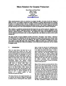
Considerable design effort has been dedicated to modifying the CORDIC algorithm with the aim to overcome the above problems (Figure 2). Figure 2. Fast CORDIC schemes We have considered four redundant CORDIC algorithms and have estimated their latency times according to the equations in Table 1 [Marx99]. The termination algorithm originally proposed by [Chen72] allows quitting the iteration process as early as possible, modified Booth encoding can be used for the same purpose [Timm92]. The following notation has been used in Table 2: τ - delay of a full adder; τ (log 2 n) - the upper
bound of an n-bit non-redundant fast addition; δ - delay of a redundant adder, independent of the bitlength; m - an arbitrary integer in the correcting method [Taka91] where a correction iteration is performed every m -th step. Table 1 Name Non-redundant method Double rotation method [Taka91] Correcting method [Taka91]
Latency expression as a function of the bit length n
n ⋅ τ log 2 n nτ + 2nδ + τ log 2 n
(n − (n + 1) m )(τ + δ ) + 2( (n + 1) m + log 2 n)(τ + δ )
Prediction method [Timm92]
nδ + τ log 3 n − 1 log 2 n + τ log 2 n
Prediction with termination method [Timm92]
δ (n + 1) 2 + τ log 3 ((n + 1) 2 − 1 log 2 n + τ log 2 n + δ log(n 2)
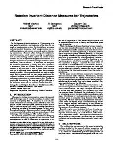
Figure 3 shows graphically the latency of the CORDIC implementations based on the expressions in Table 1 and estimated delays for XC4000XL using ratio r ≡ δ τ = 2 . It suggests that the prediction with termination method [Timm92] might lead to the fastest FPGA implementation.
4
Figure 3. Estimated latency of CORDIC implementations in XC4000XL 4. Redundant Adder Implementation in XILINX XC4000 Family In RSD representation, number Y can be viewed as the difference between two positive binary *
numbers Y and Y
**
n
n
i =0
i =0
. We have:
Y = ∑ yi ⋅ 2i = ∑ ( yi − yi ) ⋅ 2i with y i , y i ∈ {1, 0 } *
**
*
**
(12)
The conventional one-bit full adder assumes positive weights to all of its binary inputs and two outputs. Such adders can be generalised to four types of adder cells by imposing positive and negative weights to the binary input/output terminals [Hwan79]. Figure 4 shows the names and logic symbols of four types of generalised full adders. Each type of adder is named by the number of negatively weighted inputs contained in it.
Figure 4 Generalised Full Adders [Vand90] The addition of two signed digit (SD) numbers Y and Z can be performed by cascading two levels of generalised full adders of types 1 and 2. The logic circuit implementing the chosen function is sketched in Figure 5. The main drawback of this computation scheme with two numbers in redundant form is the amount of hardware, which is twice that in the carry-save case [Vand90].
5
Figure 5 Redundant signed digit adder [Vand90] The ripple-carry (RC) adder and the redundant sign-digit (SD) adder have been implemented in XILINX 4010XL and compared. The RC adder uses the XILINX dedicated carry logic and takes 0.5 CLBs per bit. The minimum implementation of the SD adder in Figure 5 has been achieved by the mapping illustrated in Figure 6, where the S1n_generator comprises the logic of the two full adders *
**
that generate the S1 output and the S2a_generator comprises the logic that generates the S 2 output. This mapping requires 2 CLBs per bit. As can be seen from the latency results in Figure 7, where RCA is the RC adder and ISDA is the SD adder, the delay of the RC adder is nearly equivalent to the delay of the SD adder up to 16 bits , however starting from 32 bits the SD adder performs much better. 5. FPGA Implementation of CORDIC - Experimental Results A non-redundant cascaded fully combinational 14-bit CORDIC sine/cosine generator has been implemented in XC4010XL. The design consumes 210 out of 400 CLBs. It has been found that the 2
CLB consumption increase for the cascaded structure is of the order O ( n ) , and a 16-bit design was not possible to implement in the same FPGA device. The worst case delay as shown by the XILINX Foundation Series timing analyser is 107.9ns yielding 5.3 MHz – with the routing delay prevailing and accounting for approximately 60% of the total delay. An iterative 16-bit CORDIC sine/cosine generator with RC adder has also been implemented in XC4010XL. The design occupies 162 CLBs out of 400, the three RC adders need 1.5 CLBs per bit, however the Barrel shifter is area consuming taking 41 CLBs. The delay is 588 ns yielding 1.7 MHz.
Figure 6
6
Figure 7 An iterative 12-bit to 32-bit CORDIC sine/cosine generator has been implemented in Actel using Synplify/Actmap and Leonardo Spectrum. Back annotated delay shows maximum speed of 2.7 MHz for 12 bits reduced to 400 KHz for 32-bit.. Summary of experimental results is shown in Table 3 and Table 4: Table 5 gives LUT synthesis results for comparison purposes. Table 3. Summary of CORDIC synthesis results based on ACTEL FPGAs Designs
Length
Iterative Iterative Iterative Iterative Iterative Cascaded Cascaded Cascaded
bits 12 14 16 24 32 12 14 16
Actmap 1 3.5.04 Area/Delay 4 420/574 538/784 674/958 1170/ ---1963/-------/-------/-------/----
Synplify 1 5.1.4 Area/Delay 4 307/334 399/414 424/462 694/727 887/1000 862/888 1970/---2853/----
Spectrum 1 5.69 Area/Delay 4 347/424 428/536 501/633 995/1248 1419/1710 1326/1378 2164/2164 2941/3718
Speed 2 ns 169.5 192.3 232.5 357.2 526.3 44.8 192.3 222.2
Frequency A54SX16-2 MHz (Fclk) 5.9 (71.4) 5 5.2 (72.5) 5 4.3 (68.5) 5 2.8 (66.6) 6 1.9 (62.5) 6 22.3 6 5.2 3 4.5 3
Table 4. Summary of CORDIC synthesis results based on XILINX FPGAs Design
Length
Iterative Iterative Iterative Iterative Iterative Cascaded Cascaded Cascaded
bits 12 14 16 24 32 12 14 16
Foundation 7 Express 1.5 Area/Delay 106/139 133/145 162/178 317/376 506/626 210/210 288/288 378/378
Target Device XC4010XL-09 XC4010XL-09 XC4010XL-09 XC4062XL-09 XC4062XL-09 XC4010XL-09 XC4010XL-09 XC4062XL-09
Speed 2
Frequency
ns 370.3 526.3 588.2 1643.8 2480.6 187.6 192.9 330
MHz (Fclk) 2.7 (32.1) 1.9 (27.5) 1.7 (27.2) 0.6 (14.6) 0.4 (12.9) 5.3 5.2 3.1
7
Table 5. LUT synthesis results Design A54SX16-3
Length bits 12 16
LUT LUT
Actmap 1 3.5.04 Area/Delay 4 513/859 1899/---- 8
Synplify 1 5.1.4 Area/Delay 4 384/453 946/---- 8
Spectrum 1 5.69 Area/Delay 4
Speed 2
Frequency
ns 43.66 84.03
MHz (Fclk) 22.1 11.9
Note 1 All synthesis tools operated in a "push-button" fashion with maximum optimisation enabled were Note 2 Note 3 Note 4 Note 5 Note 6 Note 7
available. Speed estimate based on Vital simulation using typical operating conditions. Estimate frequency given by Synplify All module count given by Designer Place and Route software. Actel Netlist Selected Synplify Netlist Selected Foundation Express build 3.1.140
Note 8
---- Synthesis not performed
6. Application Legendre polynomials - the first step of the IGRF model The Earth’s Magnetic Field computation as part of satellite attitude determination system is a very computationally intensive procedure and is mainly done in software. A structure based on CORDIC modules has been proposed [Vlac99] for the calculation of Legendre polynomials - the first step of the International Geomagnetic Reference Field (IGRF) model [Wert85]. It consists of four blocks comprising CORDIC modules for sine/cosine as well as other functions and a control block. The estimated delay based on a 32-bit iterative CORDIC module implemented in XC4085XL was compared with the delay of the software implementation running on a Pentium 333 MHz computer for five different values of the constants m, l . The improvement in speed was 44% for m = l = 10 , 37% for m = l = 15 , 32% for m = l = 20 , 28% for m = l = 25 and 23% for m = l = 36 . Direct Digital Synthesis Suitable for more than 14 bits, no need of in-phase / Quadrature components 7. Conclusions The analysis of the adder delay have shown that starting from 32 bits the redundant SD adder would have a smaller delay than an RC adder implemented using the XILINX fast carry chain, however it will require a CLB consumption equal to four times that of the RC adder.
8. References [Andr98] R.Andraka. A Survey of CORDIC Algorithms for FPGA Based Computers – Proc. Of the 1998 CM/SIGDA Sixth International Symposium on FPGAs, f1bruary,1998, Monterey, CA, pp.191200. [Bake76] P.W.Baker. Suggestion for a Binary Cosine Generator, IEEE Transactions on Comput., February, 1975, pp. 1134-1136. [Chen72] T.C.Chen. Automatic Computation of Exponentials, Logarithms, Ratios and Square Roots, IBM J. Res.Development, July, 19972, pp.380-388.
8
[Erce87] M.D.Ercegovac, T.Lang. Fast Cosine/Sine Implementation Using CORDIC Iterations, IEEE Trans. On Comput., vol.40, n 9, 1987, pp. 222-226 [Marx99] M.Marx. FPGA Implementation of sin(x) and cos(x) Generators Using the CORDIC Algorithm, Final Year Project Report, School of Electronic Engineering, University of Surrey, Guidford, UK, 1999. [Pirs98] P.Pirsch.Architectures for Digital Signal Processing, John Wiley & Sons, 1998. [Taka91] N.Takagi. Redundant CORDIC Methods with a Constant Scale Factor for Sine and Cosine Computation, IEEE Trans. On Comput., vol. 40, n 9, 1991, pp. 989-994. [Timm92] D.Timmerman, H.Hahn, B.J.Hosticka. Low Latency Time CORDIC Algorithms, IEEE Transactions on Comput., vol.41, n 8, 1992, pp.1010-1014. [Timm91] D.Timmerman, H.Hahn, B.J.Hosticka, B.Rix. A New Addition Scheme and Fast Scaling Factor Compensation Methods for CORDIC algorithms, Integration – the VLSI Journal, vol. 11, n 1, 1991, pp. 85-100. [Vand90] A. Vandemeulebroecke, E.Vanzieledhem, et al. A New Carry-Free Division Algorithm and its Application to a Single Chip 1024-b RSA Processor”, IEEE Journal of Solid-State Circuits, vol.25, n 3, 1990, pp.748-755. [Vank96] J.Vankka. Methods of Mapping from Phase to Sine Amplitude in Direct Digital Synthesis, Proc of the 1996 IEEE International Frequency Control Symposium, 1996, pp. 942 –950. [Vlac99] A. Vlachos. Design and Implementation of CORDIC Modules for ADCS, MSc Project Report, School of Electronic Engineering, University of Surrey, Guidford, UK, 1999. [Vold59] J.Volder. The CORDIC Computing Technique, IRE Trans. Comput., Sept. 1959, pp.330-334. [Walt71] J.S. Walther. A Unified Algorithm for Elementary Functions, Proc. AFIPS Spring Joint Computer Conference, pp.379-385, 1971. [Wang96] A Unified View of CORDIC Processor Design, in Application Specific Processors, Ed. By Earl E. Swatzlander, Jr., Kluwer Academic Press, 1996, pp.121-160. [Wert85] J. Wertz. Spacecraft Attitude Determination and Control, D.Ridel Publishing Company, London, 1985.
9