Multi-Clock SoC Design using Protocol Conversion Roopak Sinha, Partha S. Roop University of Auckland New Zealand rsin077,
[email protected]
Samik Basu Iowa State University USA
[email protected]
Abstract The automated design of SoCs from pre-selected IPs that may require different clocks is challenging because of the following issues. Firstly, protocol mismatches between IPs need to be resolved automatically before IPs are integrated. Secondly, the presence of multiple clocks makes the protocol conversion even more difficult. Thirdly, it is desirable that the resulting integration is correct-by-construction, i.e., the resulting SoC satisfies given system-level specifications. All of these issues have been studied extensively, although not in a unifying manner. In this paper we propose a framework based on protocol conversion that addresses all these issues. We have extensively studied many SoC design problems and show that the proposed methodology is capable of handling them better than other known approaches. A significant contribution of the proposed approach is that it nicely generalizes many existing techniques for formal SoC design and integrates them into a single approach.
1. Introduction A system-on-a-chip (SoC) consists of multiple components (IPs) that collaborate and communicate with each other to achieve system behaviour. The SoC design process is affected by several issues like the selection of IPs, their interconnection into overall system, and validation of correctness of the overall system. The main problems with the integration of preselected IPs are, (a) the possibility of control, data or clock mismatches [9] between IP protocols that prevent proper inter-IP communication, and, (b) the problem of ensuring that IPs (after mismatches are resolved) integrate such that desired high-level behaviour is met. The focus of this paper is to provide a unifying solution for the automatic resolution of protocol mismatches and the correct-by-construction design of SoCs that use multiple clocks. Some preliminary ideas of the approach were first published in [11]. These have been substantially extended and reformulated in [10]. The proposed algorithm can automatically generate a converter that can integrate two or
Zoran Salcic University of Auckland New Zealand
[email protected]
more IPs such that mismatches are resolved and the converted system satisfies desired specifications. The main contributions of this paper are as follows. Firstly, an automatic design technique for multi-clock (which also includes single clock systems as a special case) SoCs is proposed. Precise conditions for the existence of converters are identified. Furthermore, it is shown that SoCs can be constructed in a single-step or by the successive (incremental) addition of new IPs, called successive conversion.
1.1. Related Work A number of protocol conversion approaches for SoC have been proposed earlier [2, 5, 9]. In [5], a correct-byconstruction SoC design technique is presented. The work identifies precise conditions under which two IPs are compatible, and an automatic algorithm is used to generate an interface to make them compatible. A protocol conversion approach based on [5] is presented in [2]. The main contributions of this approach are the precise modelling of commercial bus protocols, a protocol conversion algorithm that always yields converters that can be translated to HDL, and converter sizes that are bounded by the size of the given protocols. However, this approach generates converters for protocol pairs only and bridges data-width mismatches on an abstract level by avoiding unbounded data operations on any path in the converted system. Furthermore, both [5] and [2] are restricted to single-clock systems and as the notion of compatibility is limited to ensuring that IPs detect and respond to actions performed by each other, the approach cannot guarantee that a given system satisfied high-level functional specifications. Passerone et al [9] present a gametheoretic formulation for protocol conversion but no algorithm is provided, data or clock mismatches are not handled, and only uni-directional IP communication is allowed. Tab. 1 presents a comparison between existing formal approaches. It shows that each technique uses different representations for protocols and algorithms to find a converter1. Furthermore, some approaches like [5] and [12] do 1 The
following abbreviations are used in Tab. 1. LTS = labelled tran-
Input (Protocols)
Input (spec.)
Multiple Protocols
Algorithm
Uncontrollable Signals
Buffering
Data
Multi-clock
Approach Avnit et al. [2] Passerone et al. [9] D’Silva et al. [5] Kumar et al. [6] Tivoli et al. [12] Proposed approach
SPA LTS SPA DES LTS SKS
× LTS × DES × CTL
× × X X X X
refinement game-theoretic refinement Supervisory control Coverability-based module-checking
× × × X X X
X X X × X X
limited × limited × × X
× × × × implicit X
Table 1. Features of various protocol conversion approaches not admit additional specifications (describing the expected system behaviour) whilst the others require specifications to be represented as automata. Most approaches can generate converters that control multiple (more than 2) protocols. Some approaches [2, 5, 9] do not support uncontrollable signals while [6] does not allow converters to explicitly buffer control signals. The handling of data-width mismatches is limited in most existing approaches while none handle the conversion of multi-clock systems. In contrast, the approach proposed in this paper is more general as it can deal with uncontrollable events, arbitrary data width mismatches, clock mismatches and control signal mismatches.
Definition 1 (SKS). A Synchronous Kripke structure SKS is a tuple hAP, S, s0 , I, O, R, L, clki where AP = U APcontrol APdata is a set of propositions where APcontrol is the set of control labels and APdata is the set of data labels, S is a finite set of states with s0 ∈ S being the initial state, I and O are finite, non-empty sets of inputs and outputs respectively, R ⊆ S × {t} × B(I) × 2O × S is the transition relation where B(I) represents the set of all boolean formulas over I (the event t represents ticking of the clock clk), and L : S → 2AP is the state labelling function. A SKS has a finite set of states S with a unique start state s0 . Each state s is labelled by a subset of the atomic propositions in AP. The labelling function L can be used to obtain the labels of any state in the Kripke structure. AP is partitioned into two sets: APcontrol which contains propositions that indicate the control status of the SKS (status flags), and APdata that contains propositions that signify data I/O. All transitions in a Kripke structure trigger with respect to the tick of the clock clk and a boolean formula over the set of inputs (to be satisfied when clk ticks). For transi-
1.2. Overview The SoC design approach presented in this paper involves the following steps. First, IP protocols are described using synchronous Kripke structures, or SKS, that describe IPs’ behaviours with respect to their individual clocks. Next, each SKS is oversampled [5, 12] with respect to the fastest clock in the SoC, in order to ensure that all SKS describe the behaviour of individual protocols with respect to a single-clock system. All oversampled protocols are then composed using synchronous parallel composition that produces their maximal combined behaviour in the form of a single SKS. This composition, along with a set of high-level specifications described using Computation Tree Logic (CTL), is processed by an automatic converter generation algorithm that, if possible, automatically generates a converter to control the composition in order to satisfy given specifications.
b/o
tions of the type (s, t, b, o, s′ ) ∈ R, the shorthand s − −→ s′ b/o
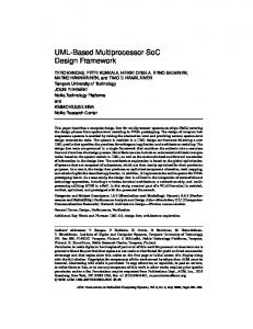
is used. For any transition s − −→ s′ leading to state s′ such ′ / the that s is labelled by a data label ([L(s′ ) ∩ APdata ] 6= 0), SKS performs a data-operation. Without loss of generality, it can always be considered that the SKS have only complete monomials as input labels [8]. In this paper, we restrict SKS to be reactive and deterministic, that is, each state s ∈ S must have a single transition with respect to every complete monomial b ∈ B(I). The function Out(b) returns the set of inputs that must be present for a monomial b to be true. Fig. 1(a) shows the protocols of the IPs of an SoC based on the AMBA ASB [1]. The SoC contains 2 masters: producer (PP ) and consumer (PC ), and 2 slaves: reader (PR ) and writer (PW ). For the sake of illustration, the bus protocol is abstracted to just its arbiter (PA). The masters, slave and arbiter, each modelled as a SKS, execute using the clocks mclk, sclk and bclk respectively. Consider the consumer
2. Preliminaries 2.1. Protocol Representation Protocols are represented as Synchronous Kripke structures, or SKS, defined as follows. sition systems, SPA = Synchronous Protocol Automata, DES = discrete event systems, SKS = synchronous Kripke structures, CTL = Computation Tree Logic.
2
(a) SoC layout
(b) The clock automaton
Figure 1. A multi-clock SoC and a clock automaton CA that emits clk at specific intervals, P can be oversampled to represent its execution with respect to the base clock clkCA that drives CA. This approach, called SKS oversampling, allows representing the execution of all IPs of an SoC with respect to the clock of the given clock automaton. Fig. 2 shows the resulting SKS PWCA when the slave writer protocol PW , shown in Fig. 1(a), is oversampled with respect to the base clock mclk of CA shown in Fig. 1(b). Each state in PWCA corresponds to a unique state in PW and a unique state in CA. PWCA has the same input and output sets as P. The transitions of a state (w, ca) in PWCA depends on ca. If ca’s transition to its unique successor ca′ emits the clock signal sclk (the driving
master protocol PC . It contains 4 states with a unique initial state c0 . At each tick of mclk, there is a transition in PC with respect to every possible input combination. A transition to c3 (labelled by the data proposition DIn16 ) results in a dataoperation place where PC reads 16-bits from the SoC data bus. In the rest of this paper, conversion is assumed to be carried out between PA , PC and PW only. The IPs of the SoC shown in Fig. 1(a) execute using different clocks. As clocks are usually derived from a common on-chip clock (the fastest clock in the SoC), the relationship between clocks can be described using a clock automaton. The clock automaton CA for the SoC example presented in Fig. 1(a) is shown in Fig. 1(b). The clock automaton is a synchronous FSM driven by the clock mclk. It emits mclk at every tick while the slower clocks sclk and bclk are emitted at different instances, depending on their frequencies.
b/o
clock of PW ), (w, ca) allows each transition w − −→ w′ of w b/o
by having a corresponding transition (w, ca) − −→ (w′ , ca′ ). ′ However, if the transition from ca to ca does not result in the emission of clk, w can not sample environment inputs in this tick. Hence, state (w, ca) has a single transition true/0/
(w, ca) − −− −→ (w, ca′ ), that models a delay. After all protocols have been oversampled, their synchronous parallel composition, that describes their unrestricted concurrent behaviour, is computed. Definition 2 (Synchronous Parallel). Given two SKS P1 = hAP1 , S1 , s01 , I1 , O1 , R1 , L1 , clki and P2 = hAP2 , S2 , s02 , / their parI2 , O2 , R2 , L2 , clki, such that I1 ∩ I2 = 0, allel composition is the SKS P1 ||P2 =hAP1||2 , S1||2 , s01||2 , I1||2 , O1||2 ,R1||2 , L1||2 ,clki where AP1||2 = AP1 ∪ AP2 , S1||2 = S1 × S2 , s01||2 = (s01 , s02 ), I1||2 ⊆ I1 ∪ I2 , O1||2 = O1 ∪ O2 , L1||2 ((s1 , s2 )) = L1 (s1 ) ∪ L2 (s2 ), and R1||2 ⊆ S1||2 × {t} × B(I1||2 ) × 2O1||2 × S1||2 is the transition relation such that
Figure 2. The oversampled slave writer
b1 /o1
b2 /o2
for any (s1 , s2 ) ∈ S1||2 ), if s1 −−−→ s′1 and s2 −−−→ s′2 ,
Given a SKS P that executes using a specific clock clk 3
b1 ∧b2 /o1 ∪o2
initially. To ensure that no overflows or underflows happen, the following CTL property is used:
(s1 , s2 ) −−−−−−−−→ (s′1 , s′2 ). For the SoC example shown in Fig. 1(a), as the focus is to generate a converter for the protocols PA , PC and PW , we compute the synchronous composition PACA ||(PCCA ||PWCA ).
ϕd ≡ AG(0 ≤ cntr ≤ 32) The above property requires that in any execution of the (converted) system, if the counter is updated with respect to each data label, it must never exceed the bounds [0, 32]. For example, we must never encounter two consecutive W rt32 without read operations in between them. We can also describe properties that combine control and data aspects of a design. For the SoC example, one such property that requires the data-bus to be empty when all IPs are idle, is:
2.2. CTL Properties To integrate the protocols PA , PC and PW shown in Fig. 1(a) into an SoC, the following CTL properties are used. [ϕ1 ] AGEFDIn16 : The consumer master can always eventually read data from the system data bus. [ϕ2 ] AGEFDOut32 : The memory writer protocol can always eventually write data.
ϕ5 ≡ AG(Idlea ∧ Idlec ∧ Idlew ) ⇒ (cntr = 0)
[ϕ3 ] AGEFOpt2 : From every reachable state in the system, there must be a path that reaches a state where he arbiter grants access to the consumer master.
Control and/or data constraints describe the desired behaviour of protocols after integration. We now introduce converters to guide protocols to meet these constraints.
[ϕ4 ] AG(¬Idlec ⇒ Opt2 ): Whenever the master is active (not in its idle state), the arbiter should have granted it bus access (by entering state Opt2 ).
3. Converters A converter acts as an interface between IPs and their environment (other IPs). It controls the participating protocols at each clock tick (of the base clock of the given clock automaton) by following a precise sequence of interactions with the environment and the protocols (shown in Fig. 3).
Control constraints state the desired sequence of control states when IPs communicate with each other. The desired data behaviour is described using data constraints. Data constraints typically require that no data overflows or underflows during inter-protocol communication. These are described using data counters. We show how a data counter can be formulated for the SoC example given in Fig. 1(a). Firstly, each data label (DIn16 and W rt32 ) is assigned a weight depending on the number of bits its corresponding operation adds/removes to/from the data bus. Hence Wt(DIn16 ) = −16 and Wt(W rt32 ) = +32. Next, weights are normalized by dividing them by the greatest common divisor GCD of the absolute weights of all data labels. For labels W rt32 and DIn16 , the normalized weights are Wtnm (W rt32 ) = 2 and Wtnm (DIn16 ) = −1 (GCD = gcd(32, 16) = 16). Now, the bounds on the capacity K of the data-bus are computed using the following constraints: 1. K ≥ max(|Wt(W rt1 )|,... ,|Wt(W rtn )|, |Wt(Rd1 )|, ... , |Wt(Rdm )|)
Figure 3. The exchange of signals between converters, protocols and environment
2. K ≥ GCD × [|min(Wtnm (W rt1...n ))| + |min(Wtnm (Rd1...n ))| − 1]
The first constraint requires that the bus can allow the largest read/write to happen. The second constraint ensures that whenever the medium does not have enough data to allow a read or a write, it must be able to allow the smallest write/read operation. For the SoC example, as the data-bus width is fixed, we must check if it conforms to the above constraints. The first constraint requires that K ≥ 32 (largest absolute weight of a data label), and the second constraint requires that K ≥ 16 × [2 + 1 − 1] or K ≥ 32. The data-bus width of 32 bits satisfies these constraints. After the above computation, a data counter cntr is introduced to track the status of the communication medium. cntr is initialized to 0 to signify that the medium is empty
Firstly, the converter samples the environment for any uncontrollable signals (environment signals are uncontrollable because the converter has no control over their emission). Next, the converter emits to the protocols a set of signals that triggers a unique transition in the current state of the protocols. This set of signals must contain all environment signals present in the current tick, and may additionally contain some signals that the converter has previously buffered (read from the protocols earlier) and signals that the converter generates artificially (protocol inputs emitted neither by the environment nor by the protocols). 4
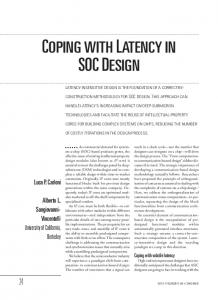
(a) A converter for the SoC example
(b) The converted SoC
Figure 4. Conversion for the SoC example The signals emitted by the protocols during this transitions are read back by the converter. Some of these signals (that are shared) are buffered by the converter. The converter maintains a 1-place buffer for each bufferable input. The remaining signals are emitted to the environment. These micro-steps can be written as a single transition of the current state C of the converter (a macro-step) as follows: C
in protocol conversion, the goal is to generate an environment under which a given system (composition of protocols) satisfies one or more specifications. The proposed algorithm reads the synchronous composition of participating IP protocols and a set of CTL formulas describing the constraints on the interaction of the given IPs. The algorithm then involves the construction of a tableau [3] where the initial goal (of the initial state of parallel composition satisfying all given specifications) is recursively broken down into sub-goals. If a successful tableau (where all subgoals are satisfied) is generated, conversion succeeds and a converter is extracted automatically from the tableau. However, if a failed tableau is obtained (when a subgoal cannot be satisfied), a converter cannot be generated. A successful tableau is shown to be the sufficient and necessary condition for the existence of a converter. Fig. 4(a) presents a converter C for the protocols PACA ||(PCCA ||PWCA ). The labels of each converter state shows the signals buffered by the converter at that state. The converter executes using the clock mclk. The resulting system (the lock step composition C //(PACA ||(PCCA ||PWCA ))) is shown in Fig. 4(b). It can be seen that the converted system satisfies all given control and data constraints.
bunc /o;oemit ;ibu f
−−−−−−−−−→ C′
where bunc is a complete monomial over uncontrollable signals, o and oemit are the sets of signals emitted to the protocols and environment respectively, and ibu f is the set of signals buffered by the converter. A converter state C always controls a unique state s of the given protocols. The C-transition fires the following s-transition. Out(b)/oemit ∪ibu f
s −−−−−−−−−−→ s′ Each C and (the corresponding) s transitions combine to form the following transition in their lockstep-composition: bunc /oemit
C//s − −−−−−→ C
′
//s′
4. Results
The lock-step composition of a converter and protocols is reactive and deterministic with respect to the set of uncontrollable environment signals (see [10] for details).
Tab. 2 highlights the range of problems that can be addressed by the proposed technique. The first two columns identify the goal of conversion, and the third columns shows the types of mismatches (C=control, D=data, Clk=clock) between each set of IPs. Problem 1 involves building a complex bus (AMBA ASB) from simple components (that model bus policies) by using an automatically generated converter. Problems 2 and 3 involve constructing a converter that can allow a master (using a different clock)
3.1. Converter Generation Algorithm Converters are automatically generated by a conversion algorithm (details appear in [10]). This is a variant of the module checking problem [7] that is an approach for verifying (model checking) if an open system satisfies a given temporal property under arbitrary environments. Similarly, 5
No. 1 2 3 4 5 6 7 8 9 10
Problem Integration of Bus Policies (ASB) ASB/AHB, 1 master with burst transfer APB, single master with burst transfer Producer-consumer over ASB (related width ratios: 1:2, 2:1, 1:1) Producer-consumer over ASB (arbitrary width ratios: 7:3, 3:8, 4:15) Sequencing of activation in 5-IP SoC Sequencing of data in 5-IP SoC SoC with multiple data-channels Single step construction of 7-IP SoC 3-step construction of 7-IP SoC
Mismatches C C;Clk C;Clk C;D;Clk
matches between multiple IPs can be resolved, and those IPs can be integrated into a correct-by-construction SoC. This is unlike existing approaches that focus exclusively on mismatch resolution or correct-by-construction design. In the proposed setting, IP protocols are described using Synchronous Kripke Structures, each executing using its individual clock. An automatic converter generation algorithm based on tableau construction is used to generate a converter, if possible, that bridges mismatches and guides the IPs such that their interaction is consistent with high-level control and data constraints, described using CTL. Experimental results show that the proposed approach can handle a wider variety of mismatches than existing techniques. Future extensions to the proposed framework include the generation of more powerful converters (for example a converter with ”n”-place buffers for control signals) and optimizations to increase efficiency and scalability. Another exciting direction is the automatic extraction of CTL properties that describe the interaction between IPs of an SoC.
C;D;Clk C;Clk C;D;Clk C;D;Clk C;D;Clk C;D;Clk
Table 2. Implementation Results to carry out 4-packet burst transfers over different AMBA buses. For the ASB and AHB (that allow burst transfers), converters merely provide synchronization between IPs. For the APB, the converter mimics a burst transfer by activating the bus 4 times for every activation of the master. Problems 4 and 5 show that the proposed approach is capable of bridging data-width mismatches between IPs with related (multiples of each other) or arbitrary data-widths. Problems 5 and 6 show that a converter can achieve a precise sequence of activation (and/or data transfer) between the IPs of a multi-clock SoC. Problem 8 involves the construction of a converter for a SoC where IPs communicate over multiple data channels (data bus and buffers). Finally, problems 9 and 10 involve building an SoC from 7 IPs. In problem 9, the SoC is built in a single step (a single converter) while in problem 10, the SoC is built in 3 steps (3 converters) by adding 2 IPs during each stage of conversion. Traditional SoC design favors one-step construction where systems are built only after all IPs are identified. One-step construction eliminates the user effort required in the intermediate stages for successive conversion. However, a single converter to control all IPs (as in one-step conversion) is difficult to realize due to an increase in on-chip wiring congestion (that may cause latency errors due to leakage [4]). In successive conversion, converters can be built to control IPs located closer to each other. This allows reuse of SoCs as existing systems can be extended by adding more IPs. Problems such as arbitrary data-widths between multiple IPs or sequencing of control and data states cannot be handled by existing techniques, even for single clock designs. For example, the data-width mismatch between a consumer-producer protocol pair with word sizes of 2 and 9 bits respectively cannot be bridged by any other approach.
References [1] ARM. AMBA Specification (Rev 2.0), 1999. [2] K. Avnit, V. D’Silva, A. Sowmya, S. Ramesh, and S. Parameswaran. A formal approach to the protocol converter problem. In DATE, pages 294–299, March 2008. [3] G. Bhat, R. Cleaveland, and O. Grumberg. Efficient onthe-fly model checking for CTL∗ . In LICS, pages 388–397, 1995. [4] L. Carloni, K. McMillan, A. Saldanha, and A. SangiovanniVincentelli. A methodology for correct-by-construction latency insensitive design. In ICCAD, pages 309–315, 1999. [5] V. D’Silva, S. Ramesh, and A. Sowmya. Bridge over troubled wrappers: Automated interface synthesis. In VLSI Design Conference, page 189, 2004. [6] R. Kumar, S. Nelvagal, and S. I. Marcus. A discrete event systems approach for protocol conversion. Discrete Event Dynamic Systems, 7(3):295–315, 1997. [7] O. Kupferman and M. Vardi. Module checking [model checking of open systems]. In Computer Aided Verification. 8th International Conference, CAV ’96, pages 75–86, Berlin, Germany, 1996. Springer-Verlag. [8] F. Maraninchi and Y. R´emond. Argos: An automaton-based synchronous language. Computer Languages, 27(1–3):61– 92, October 2001. [9] R. Passerone, L. de Alfaro, T. A. Henzinger, and A. L. Sangiovanni-Vincentelli. Convertibility verification and converter synthesis: Two faces of the same coin. In ICCAD, pages 132–139, 2002. [10] R. Sinha, P. S. Roop, S. Basu, and Z. Salcic. An Approach for Resolving Control and Data Mismatches in SoCs. Report 667, School of Engineering, University of Auckland, 2008. www.ece.auckland.ac.nz/∼roop/documents/tech667.pdf. [11] R. Sinha, P. S. Roop, S. Basu, and Z. Salcic. A module checking based converter synthesis approach for socs. In VLSI Design Conference, pages 492–501. IEEE, 2008. [12] M. Tivoli, P. Fradet, A. Girault, and G. Gler. Adaptor synthesis for real-time components. In TACAS, pages 185–200. Springer, 2007.
5. Conclusions This paper proposes a unifying framework for the design of SoCs in which control, data-width and clock mis6