IEEE/ACM TRANSACTIONS ON NETWORKING, VOL. 12, NO. 6, DECEMBER 2004
1105
Segment Shared Protection in Mesh Communications Networks With Bandwidth Guaranteed Tunnels Pin-Han Ho, Member, IEEE, János Tapolcai, and Tibor Cinkler, Member, IEEE
Abstract—This paper focuses on the problem of dynamic survivable routing for segment shared protection (SSP) in mesh communication networks provisioning bandwidth guaranteed tunnels. With SSP, a connection is settled by concatenating a series of protection domains, each of which contains a working and protection segment pair behaving as a self-healing unit for performing local restoration whenever the working segment is subject to any unexpected interruption. We first discuss the advantages of using SSP—the ability to shorten the restoration time as well as achieve a higher throughput by saving spare capacity required for 100% restorability; then the survivable routing problem is formulated into an Integer Linear Programming (ILP), where the switching/merging node pair of each protection domain along with the corresponding least-cost working and protection segment pair can be jointly determined for a dynamically arrived connection request. A novel approach of arc-reversal transformation is devised to deal with the situation that the working segments of two neighbor protection domains may overlap with each other by more than a single node. Due to a very high computation complexity induced in solving the ILP, a novel heuristic algorithm is proposed, named Cascaded Diverse Routing (CDR), to allocate protection domains for a connection request by performing diverse routing across a set of predefined candidate switching/merging node pairs. Experiments are conducted on five two-connected network topologies to verify the ILP and the CDR algorithm. We first determine the best diameter of protection domains for the CDR scheme in each network topology. Using the results of best diameters, CDR is compared with two reported schemes, namely PROMISE and OPDA. We demonstrate in the simulation results that the path-shared protection schemes are outperformed by the SSP schemes in terms of blocking probability under all possible arrangements in the experiment and that CDR yields better performance than PROMISE and OPDA due to the extra efforts in manipulating the location of working segments at the expense of longer computation time. Index Terms—Integer linear programming (ILP), segment shared protection (SSP), shared risk link group (SRLG), survivable routing, working and protection paths.
I. INTRODUCTION
S
URVIVABILITY has emerged as one of the most important issues in the design of modern communications networks with bandwidth guaranteed tunnels. Survivable routing is rec-
Manuscript received April 13, 2003; revised September 22, 2003; approved by IEEE/ACM TRANSACTIONS ON NETWORKING Editor A. Orda. P.-H. Ho is with the Electrical and Computer Engineering Department, University of Waterloo, Waterloo, ON N2L 3G1 Canada (e-mail: pinhan@bbcr. uwaterloo.ca). J. Tapolcai is with High-Speed Networks Laboratory, Department of Computer Science and Information Theory, Budapest University of Technology and Economics, Budapest H-1117, Hungary (e-mail:
[email protected]). T. Cinkler is with the Department of Telecommunications and Media Informatics, Budapest University of Technology and Economics, Budapest H-1117, Hungary (e-mail:
[email protected]). Digital Object Identifier 10.1109/TNET.2004.838592
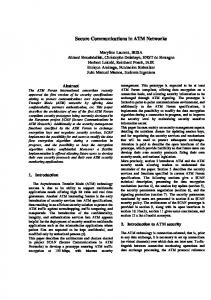
ognized as one of the best strategies to equip the networks with service continuity by preplanning link-disjoint or node-disjoint protection paths for working capacity. With a diversely routed working-protection path pair, once the working path is subject to any unexpected interruption, the corresponding service can be restored by switching over the working traffic to the protection path such that the failure is circumvented. With the emergence of some commercially applications and delay-sensitive services addressing stringent requirements on data integrity and service continuity, the design of survivable routing algorithms should not only be both capacity- and computation-efficient, but also minimize the possible restoration time for a specific connection, such that the maximum benefits can be gained in the operation of carrier networks. Segment shared protection (SSP) is one of the best approaches to meet the above design requirements, where a connection is provisioned by concatenating a series of protection domains, each of which contains a working and protection segment pair behaving as a self-healing unit for performing local restoration when the working segment is subject to any unexpected interruption. As shown in Fig. 1, when the working path segment of protection domain 2 is impaired unexpectedly (e.g., either link E-F, F-G, G-H, or H-I is cut), the restoration is performed locally within protection domain 2 such that the affected flow switches over to the backup segment at node E (called switching node of the protection domain) and merges back to the original working path at node J (called merging node of the protection domain). Comparing with its counterpart—path shared protection [10]–[18], SSP has been reported to achieve a better throughput by maximizing the extent of spare capacity resource sharing [2], [7], [21]. It can also impose a stringent limitation on the restoration time for a specific application by constraining the length/hop count of the working and protection segment in each protection domain. The major difficulties of implementing SSP lie in the dependency between the working and spare capacities as well as the exponentially enlarged design space with the network size in identifying a set of switching/merging node pairs to form protection domains for a connection request. Thus, most previous studies focus on heuristic approaches to solve the problem. In [2], a framework known as Short Leap Shared Protection (SLSP) is proposed, which implements SSP by preassigning a series of switching/merging node pairs along a given working path. The capacity efficiency with SLSP is expected to be further improved if the working and backup segments can be jointly determined. In [3], an algorithm is developed to find the working path first followed by its backup path segments. The study is characterized by the fact that the
1063-6692/04$20.00 © 2004 IEEE
1106
IEEE/ACM TRANSACTIONS ON NETWORKING, VOL. 12, NO. 6, DECEMBER 2004
Fig. 1. Illustration of SSP.
spare capacity sharing is not considered until the physical routes of the backup path segments are defined. In [4] and [5], the authors propose two similar dynamic algorithms to switch over working traffic for each link from its immediate upstream node and merge back to the original path at any of the downstream nodes. Neither study imposes any limitation on the lengths of the backup paths and may not be able to guarantee the restoration time when a failure occurs. Note that the unnecessarily lengthy backup paths have been witnessed to impair the overall performance even if they share spare capacity with the other backup paths [10], [12]. The study of [6] provides an algorithm for computing QoS paths with restoration, which is characterized by considering multiple link metrics in searching the working and protection segments. This study does not consider resource sharing and adopt exhaustive searching for those protection segments for the working path. The study in [7] proposes an Integer Linear Programming (ILP) formulation for SSP to determine the switching/merging node pairs along the working path given in advance. The algorithm is characterized by the efforts of inspecting all possible number of protection domains for a connection request and all possible combinations of allocation under each given number of protection domains. Since the formulation needs to have the working path first before the protection segments can be derived, the solution may be far from the optimal if the working path is not well selected. The study in [8] takes a very similar approach to that in [7]. The algorithm finds a protection segment for each link along the working path given in advance, in which “backtrack” by hops is allowed, where can be an arbitrary positive integer or infinity. In the study of [9], a heuristic algorithm is proposed for SSP, called Optimal Protection Domain Allocation (OPDA), where a graph transformation algorithm, called transferred graph of cycles, is devised. Since the algorithm needs to enumerate and align simple cycles in the network topology as candidate cycles for a given working path, it may impair the capacity efficiency if only a limited number of cycles can be inspected within the allowed computation time. It is notable that all of the above schemes deal with work and protection paths separately, which are also known as Active Path First (APF) [10]. To jointly determine a working and protection path pair, some studies focus on developing a programming-based solution [4], [11]–[13]. One of the key issues in formulating the problem under the complete routing information scenario [4] (i.e., the algorithm is aware of all of the working and protection paths along each link) is that the routing of the working path and the
dependency between working and spare capacity along each link must be handled in a single step. Besides, the consideration of multiple states for the protection path to consume spare capacity along each link may easily leave the formulation nonlinear [4]. Therefore, to the best of our knowledge, a linear programming-based solution that can optimally solve the least-cost working and shared protection path pair according to the current link-state has never been reported before, let alone the case of SSP, which is considered to be much more complicated. The study in [4] provides an Integer Programming (InP) in the complete routing information scenario for solving the end-to-end working and shared protection path pair according to the current link-state. The formulation is nonetheless nonlinear and cannot be solved by most of the commercially available LP solvers. The study in [11] provides a heuristic-based ILP formulation to deal with the problem, where two scaling parameters are introduced to avoid the nonlinearity possibly induced when multiple states of spare capacity along each link are considered. The study in [12] and [13] focuses on the complete routing information case and provides an ILP formulation that can solve the problem with two states of spare capacity along each link for the protection path—either sharable or nonsharable, where the link bandwidth constraint can never be addressed. It is clear that an ILP formulation for SSP considering all possible states of spare capacity consumption along each link in the complete routing information scenario has never been seen before. This paper contributes to formulating the problem into an ILP working under the complete routing information scenario in which the location of the switching/merging nodes and the corresponding working and protection segment pairs for a connection request can be derived in a single step according to the current link-state. This is the first linear formulation that can handle the dependency between working and spare capacity for SSP, where a novel method of arc-reversal transformation is devised to deal with the situation that working segments of two neighbor protection domains may overlap with each other by more than a single node (as shown in Fig. 1). To avoid the nonlinearity possibly incurred when dealing with the multiple states for a protection segment to take spare capacity, a graph transformation technique is devised to facilitate the formulation. Although the ILP can yield the least-cost (or optimal) working and protection segment pairs for a connection request, the solving of the ILP nonetheless takes an intolerably large amount of computation time. Therefore, this paper also introduces a novel heuristic algorithm for solving the problem, called Cascaded Diverse Routing (CDR), aiming to trade the
HO et al.: SEGMENT SHARED PROTECTION IN MESH COMMUNICATIONS NETWORKS WITH BANDWIDTH GUARANTEED TUNNELS
optimality in performance with the computation complexity. The basic idea of CDR is to predefine a set of candidate switching/merging node pairs, between each of which a diverse routing algorithm, called Iterative Two-Step-Approach (ITSA) [12], is conducted to find the corresponding working and protection segment pair. We compare CDR with the heuristic approaches reported in [7] and [9] through simulation, namely PROMISE and OPDA, and examine the offset of optimality in each case referring to the solutions from the ILP formulation. This paper is organized as follows. In Section II, an overview on SSP and spare capacity resource sharing is conducted, where the cost functions for both working and protection segments are defined. In Section III, the ILP formulation for solving the SSP problem is presented. Section IV presents the heuristic algorithm, CDR. In Section V, CDR is compared with two other reported schemes through simulation and is verified by the results from the ILP solution. Section VI concludes this paper.
Fig. 2.
1107
Example to illustrate the SRLG constraint.
II. PROBLEM DEFINITION A. Concepts of Shared Risk Link Group Shared Risk Link Group (SRLG) is defined as a group of network elements (i.e., either links, nodes, physical devices, software/protocol identities, or a mix) subject to the same risk of single failure. In practical cases, an SRLG may contain multiple seemingly unrelated and arbitrarily selected links/nodes. We define that a working path is involved in an SRLG if it traverses through any network element that belongs to the SRLG. A path may be involved in multiple SRLGs. A working path is said to be SRLG-disjoint with its protection path if the two paths are not involved in any common SRLG. In this study, the SRLG-disjointedness for a working and protection path pair is the major effort of achieving 100% restorability for the working data flows under the single failure scenario. Without loss of generality, this study focuses on the case that each arc in the network topology is an SRLG. Under such a premise, it is easy to see that a working path traversing through hops will be involved in no more than different SRLGs. We raise the assumption that the probability of each physical conduit to be subject to a failure is independent. In other words, to achieve 100% restorability, it is sufficient and necessary that every link traversed by the working path is protected by at least one link-disjoint protection path. In this study, all of the working paths are assumed to be loop-less. A working path may contain multiple protection domains, each of which has a protection path. The spare capacity taken by backup path segments is called spare channels that are only reserved but not configured during the normal operation. Therefore, the spare channels can also be used by some best-effort traffic that can tolerate a service interruption. In the event that a failure occurs that interrupts a working path (such as a fiber-cut or loss of signal due to the failure of any network element), the switching fabric structures in the nodes along the corresponding protection path are configured by prioritized signalling followed by traffic switchover to recover the original service supported by the working path. Therefore, the protection paths of different working paths can reserve the same spare channels if the working paths are not involved in a common SRLG, and are considered to share the same risk of single failure. In this study, two working
Fig. 3. Comparison between the path shared protection and SSP. (a) Path shared protection. (b) SSP with switching-merging pairs (A, C), (C, E), and (E, G) for the first, second, and third protection domains, respectively.
paths share the same risk of single failure if and only if they take any common arc in the network. In other words, whether or not two protection paths can share a spare channel depends on the physical location of their working lightpaths. The dependency is the reason for the existence of the SRLG constraint [1]. A simple example is shown in Fig. 2. W1 and P1 form a working and protection path pair. The protection path of W2 (any other working path) should exclude the possibility of using any of the spare channels taken by P1 because W2 traverses link A-B, which shares the same risk of a single failure with W1. For language precision, in the following context, a “link” is always directional while an “arc” is undirectional composed of two directional links of the same ending nodes. We assume that a link is physically bundled and is comprised of several independent communication channels that provision data flows. Therefore, a failure defined in this paper is limited to a link cut that is possibly caused by a rodent bite or careless construction/maintenance efforts. We take an assumption of single failure scenario, where the algorithm only deals with the situation that a single link in the total network is unexpectedly interrupted at a moment. B. Overview of SSP The advantages of using SSP compared with path shared protection lie in not only the reduction of restoration time, but also the achievement of a larger degree of sharing. The following is an example to show the resultant capacity saving and reduced restoration time in using SSP compared with path shared protection. In Fig. 3, the network contains working path W1 (A-B-C-D-E-F-G) and its link-disjoint protection path along (A-H-C-J-E-K-G). Assume that W2 (C-D-E) is being
1108
allocated with its protection path. In case path shared protection is adopted, as shown in Fig. 3(a), the spare capacity taken by the protection path of W1 can never be shared by the protection path of W2 since both W1 and W2 are involved in a common SRLG. For SSP shown in Fig. 3(b), on the other hand, W1 is segmented into multiple segments, each of which is assigned with a switching/merging node pair and a protection segment. For example, for the second protection domain, each switching and merging node is C and E, respectively. Therefore, the protection path of W2 can share the spare capacity taken by the protection segments in the first and third protection domains. In this case, the number of working paths in an SRLG is reduced such that the total amount of nonsharable spare capacity in the network for a specific working segment is reduced, which yields better throughput. Because the restoration can be performed locally in each protection domain, the propagation time of signaling messages can be largely reduced. In this study, the link-based shared protection [2] is taken as a special case of SSP, in which every link along the working path behaves as a working path segment with a switching/merging node pair for the corresponding protection segment. The overhead in using SSP compared with path shared protection is as below. First, larger computation complexity is taken to solve the problem due to the efforts in determining the switching/merging node pair of each protection domain. Second, a new suite of signaling mechanisms must be defined. The signaling effort with SSP is briefly described as follows. After a fault on the working path occurs, it is localized immediately by the downstream neighbor node, which notifies the switching node of the protection domain to activate a traffic switchover. For the example in Fig. 1, a fault on link C-D is localized by its immediate downstream node D. A fault on link E-F is localized by the immediate downstream node F. In the former case, node D sends a notification indicator signal (NIS) to notify nodes A and F that a fault occurred in their protection domain. In the latter case, node F sends an NIS to nodes E and J for a fault notification. In the case that a failure occurs to the link or node covered by two neighbor protection domains (e.g., link E-F), the protection domain close to the source node is in charge of the failure. After receiving the NIS, the merging node (i.e., A or E) immediately sends a wake-up packet to activate the configuration of switching fabric in each node along the corresponding backup segment of the corresponding protection domain, and then the traffic can be switched over to the protection path. With the above signaling mechanism, it is clear that every node must additionally keep track of the switching node of each working path traversing through the node in the corresponding protection domain. Fault localization is necessary such that the downstream node of a failure can activate the failure recovery process, in which a higher requirement on hardware responsiveness and control complexity is needed. The largely increased computation complexity in using SSP compared with path shared protection is also a nontrivial problem that should be solved before the scheme can be practically applied. C. Definition of Cost Functions This section defines cost function and the link-state for solving a protection segment of a working path segment (or termed spare link-state). Assume a network where
IEEE/ACM TRANSACTIONS ON NETWORKING, VOL. 12, NO. 6, DECEMBER 2004
Fig. 4. Illustration of categories of capacity along link j .
and being the set of nodes and directional links, respectively. The capacity along link , , can be categorized into the following three types: 1) Free capacity (denoted as ), which is the link capacity that can be reserved as either working or spare capacity. 2) Spare capacity (denoted as ), which is the link capacity reserved by some backup segment(s). 3) Working capacity, which is the link capacity already taken by some working path and cannot be taken for any use until the corresponding working path is torn down. The cost function for finding a working path segment in the th protection domain (denoted as ) with bandwidth is as follows: if link is not reservable otherwise
(1)
where is the cost for each unit of bandwidth taken by a working path along link and is a small number defined as in this study. The link cost is custom-designed and can either be a constant (e.g., simply the bandwidth demand of the connection request for each hop) or take dynamic network traffic into consideration (e.g., the maximum reservable bandwidth along link ). In this study, the fact that link is not reservable by can only be due to , where is the free capacity along link (as illustrated in Fig. 4). The total cost of the working path is . The purpose of additionally imposing the small number in the cost function is to match the cost of backup segments, which will be defined later. For solving the backup segment of , we need first to define the corresponding spare link-state and cost function. With the presence of , the spare capacity along link can be further categorized into the following two types: ), which is the 1) Sharable spare capacity (denoted as link capacity that has been reserved by some other backup segment(s), and is sharable to the backup segment of . ), which 2) Non-sharable spare capacity (denoted as is the link capacity that has been reserved by some other protection paths, and is not sharable to the protection path of W due to the SRLG constraint. Note that , which is the total spare capacity along link . The protection path may traverse through link in any one of the following three states: 1) the case where the link has sufficient sharable spare capacity (i.e., ), in which the backup segment can take this link with the smallest cost (denoted as in this study); 2) the case where , and the backup segment must partly (or totally)
HO et al.: SEGMENT SHARED PROTECTION IN MESH COMMUNICATIONS NETWORKS WITH BANDWIDTH GUARANTEED TUNNELS
f
Fig. 5. Possible situations of a different cost function defined in (2). denotes the amount of “free spare capacity” while for “sharable spare capacity.”
sh
take free capacity along this link with an extra cost (in this case, , where is a [0,1] the spare link-state is scaling parameter determined by the location of and will be defined later); and 3) the link does not have sufficient sharable spare capacity and free capacity (i.e., ), in which the backup segment cannot traverse through this link by any means. In this case, the cost is . Due to the dependency between the working and spare capacity in the network, the parameters , , and cannot be defined until the presence of . In this study, is defined as for any link . It is clear that is 1 if there is not any sharable spare capacity available along link and is approaching 0 if is close to . In the former case (i.e., the case of ), the cost for the backup segment to take this link is , which is the same as that for the working path since all the reserved bandwidth has to be from the free capacity region as shown in Fig. 4. The spare link-state for the backup segment of can be expressed as if if if (2) Fig. 5 shows the three situations defined in (2). In Fig. 5(b) and (c), the backup segment of may partly take the free capacity region and the sharable spare capacity region; therefore, the link cost is , which is shown in the first condition in (2). In Fig. 5(a), the backup segment can have all in the sharable spare capacity region, therefore, the cost is , as shown in the second condition in (2). In Fig. 5(d), the link cost is infinity because the backup segment of cannot be supported by the residual capacity of the link, which is shown in the third condition in (2). Note that the protection path is assumed to take sharable spare capacity along a link whenever there is any sharable spare capacity available. If there is not enough sharable spare capacity along this link to cover the total bandwidth demand for protecting (i.e., ), the backup segment takes free capacity after considering all of the sharable spare capacity. Note that the adoption of the small constant is to keep the continuity between the first and second conditions in (2). In this case, the cost of link is set to as for both of
Fig. 6.
Design of mass protection path
1109
Q.
the conditions. This is also the reason we impose in the cost function for the working path shown in (1), in which the cost for the working and backup path segments to take free capacity can match each other. in (2)—the spare linkOur objective is to determine state that defines the cost of the backup segment of passing is the only variable that must be through link , in which since ). figured out (or, equivalently, Note that and are network-wide link-state specific to the presence of . Any link is, in turn, traversed by a set of working path segments denoted as , which are also the working path segments currently involved in a common SRLG of link with . The derivation of and can also be expressed in a matrix form, which is a graceful expression for determining spare capacity along each link by Liu [15]. In this case, we define the working and protection path-link incidence matrices as and , in which is a array containing all the working path segments that are involved in a common SRLG (i.e., take any common physical link) with , while is an array containing all backup segments corresponding to the working paths segments in Here we define , where is a union operation. is defined as The spare provision matrix for , which is a matrix. Applying a MAX operation upon each row of will yield a vector , which keeps the amount of nonsharable spare capacity along each link provided with the working path segment . The vector , which keeps the amount of sharable spare capacity along each link provided with the working path segment , can thus be derived by referring to the relationship , where is a vector recording the amount of spare capacity along each link. III. LINEAR FORMULATION FOR SSP This section introduces a linear formulation for the segment shared protection problem. Our approach is to find a path , called mass protection path, which is composed of all of the backup segments and some links along the working path. A simple example is shown in Fig. 6, where is (s-a-b-c-e-d). The first protection domain is formed by the working and protection segments (s-c-b) and (s-a-b), respectively, while the second is formed by (c-b-d) and (c-e-d), respectively. The allowance of overlapping between the working segments of two neighbor
1110
IEEE/ACM TRANSACTIONS ON NETWORKING, VOL. 12, NO. 6, DECEMBER 2004
protection domains is to explore the largest design space so as to guarantee the optimality of the derived solution. Note that may contain loops to reflect the fact that spare capacity sharing can happen between two protection segments of different protection domains. Let the network be denoted , where and are the set of nodes and directional links in the network, respectively. Let the source and the destination of the upcoming connection request, , be denoted as and , respectively. Three residual graphs are defined to facilitate the solving of this problem, each of which carries one or a few variables for the identification of the working and protection segment pairs. The graph for solving and is comthe working segments is denoted as for ( , , and posed of links with variables in the following formulas are assigned to this graph). , which is to The second residual graph is denoted as facilitate solving the protection segments. We need this graph to record the spare link-state because working and protection path take different suites of link-state with shared protection. This graph is composed of the links where the amount of free plus that of the spare capacity is larger than or capacity equal to (i.e., for ) ( variable in the following formulas is assigned to this graph). The third residual graph is composed of all of the links in along with the links of in a reversed direction. The inclusion of the links of in a reverse direction into is called arc-reversal transformation similar to the graph technique adopted in Suurballe’s algorithm [19]. With , we will be able to handle the reverse arcs caused by the overlapping between and , such that the route of can be identified. The variables defined in this graph are and , which will be discussed in detailed later. It is clear that we have the . Therefore, following relationship: contains forward arcs denoted as
, which are due to the
, which links of , as well as the reversed arcs denoted as are due to the reversal of link in . In the latter case, the . The reversed links direct from node to node for transformation yields the fact that, if there is a bi-directional link between node and with the amount of free capacity larger than or equal to , then will have four links between , ; , ), in which two of them dinode and (i.e., ; ) and the other two direct to node rect to node (i.e., (i.e., ; ). If the amount of free capacity is less than , and the amount of free plus spare capacity is larger than or equal to (i.e., ), then will have two di; ); otherwise, there rectional links between and (i.e., is no link between nodes and in . Please refer to Fig. 7 for an illustration of the graph transformation. In the formulation, all three of the graphs ( , , and ) are considered and indexed in an array during the implementation, and we have to keep track of the index of each directional link on different graphs even though they are in the same direction and at the same physical location. For example, we must distinguish between and , between and , and between in the array keeping the indexes of the links.
and
Fig. 7. Graph transformations for the links in , and , respectively.
G
G
G, which yields the graphs G
,
To introduce the target function of the proposed ILP formulation, the following two flow indicators are defined in each graph and : is a binary variable with a size of of defined in graph , while is an integer variable ranged with a size of defined in graph , where is the maximum number of protection domains that can be possibly handled in the problem. The target function is as follows:
(3)
is the cost per unit of working bandwidth to reserve where , which is equivalent to in (1), and is a small conlink stant that can be set such that , which is a mirror binary variable of is same as that defined in (2). to facilitate the calculation of the total cost caused by the protection segments and will be further discussed later. Each of and indicates the number of times the and working and mass protection paths traverses , respectively. The reason for setting as an integer instead of a binary variable is that path , which is composed of the protection segments of all the protection domains, may have loops in case the protection segments of two different protection domains traverse through the same link. Therefore, may be larger than 1. Therefore, the concatenation of all of yields , while the concatenation all of the links with links with forms . It is clear that the overlapped links and should not be considered when calculating between the cost for the corresponding protection segments in the target function. Besides, we should count once for each link traversed by even if traverses any link by multiple times due to the possible spare capacity sharing between protection segments of any two protection domains for the connection. Therefore, a transformation is required from the integer variable (defined in ) into a new binary variable, denoted as (defined in ). This transformation can be simply done by but filtering out those links taken by which are defined in . This filtering can be done with the following linear not in formula:
HO et al.: SEGMENT SHARED PROTECTION IN MESH COMMUNICATIONS NETWORKS WITH BANDWIDTH GUARANTEED TUNNELS
In the transformation, is zero if is zero and is 1 if . As for , it is for the protection segment taking a , which depends on per-unit of spare capacity along link and has the same physical meaning as that of the value of defined in (2) if link is equivalent to the parameter link . This statement will be discussed and verified later in this section. The target function is subject to the following constraints:
For
1111
, we have the following constraints: (6)
(7)
(4) (8)
(5)
(9)
Equations (4) and (5) are the flow conservatin constraints for the working and mass protection paths, respectively. and will be exclusive in It is important to note that
is upper-bounded by The constraint in (6) ensures that and is nonzero only if passes through . To verify (7) and (8), the following four situations are defined for a node (not the source or destination) taken by : 1) merges back to at the node; 2) switches out of at the merges back and switches out of at the node; node; 3) 4) otherwise. Equations (7) and (8) behave as a special type of for flow conservation constraint upon the net change of node in the network, which is denoted at the left-hand side of node along of the equations. In (7), the value of increases by 1 in the case of situations 1) and 2) and increases by 2 in the case of situation 3), and is unchanged otherwise. The has a lower bound constraint on the net change in terms of specified at the right-hand side of the equation, where the term
otherwise
terms of the physical links they take. However, a link can be taken by in a reversed direction only if passes through it. Besides, each reversed arc can be used only once since the algorithm only allows two working segments to be overlapped. The above statements can be formulated into the following two constraints:
where represents the reversed link of . Under the above two constraints, has to be disjoint from except for those being reversed (see Fig. 6). These two constraints arcs of not only assert the disjointedness of the working and the corresponding protection segment, but also facilitate the indication of the switching/merging nodes for each protection domain along . A pair of variables (with a size of ) and (with a size of ) is assigned to each link along and , respectively, such that the first link from the source has a label of 1; if a protection domain ends or starts at a node, the labels of the following arcs will be increased by 1. This labeling method is be the number of prosimilar to that proposed in [7]. Let . In solving the tection domains with an upper bound should be set to the upper bound formulation, the value of to guarantee the derivation of the optimal solution. If the value of is set less than (i.e., the number of protection domain in the optimal solution), the LP solver cannot return an optimal solution although we have a smaller problem size.
checks if node is taken by . It is clear that the term is 0 if and is otherwise. Therefore, node is traversed by if node is not taken by , (7) automatically holds. The four cases specified in (7) are presented as follows. In the case of 1), the increase of is 1 since and
(since
at node ). In case 2), the increase of and uation 3), increase of
merges back to is still 1 because . In sit-
is 2 since . If node
is neither a switching nor
a merging node (but it is taken by ), the right-hand side of (7) is required. becomes 0, for which no change upon Equation (8) basically has the same working principles as (7) except that, when node is not taken by , the right-hand side . Both (7) and (8) constrain the becomes 0 instead of net change of the value of to be either 0, 1, or 2, for any node taken by , depending on how path switches out and to 1 if node is the merges back to . Equation (9) sets source node.
1112
IEEE/ACM TRANSACTIONS ON NETWORKING, VOL. 12, NO. 6, DECEMBER 2004
and linksegment. This effort introduces and , domain incidence binary variables denoted as is traversed by the working and protection which is 1 if link segment of the th protection domain, respectively. Note that the is the variable in the foronly variable defined in graph mulation. We can alternatively define the variable upon instead of having a new graph , in which the formulation turns out to take only two residual graphs. Although it is much more varitractable to implement, there would be at most ables unnecessarily induced due to the fact that we do not need on the reversed links of . to define For , the following constraints are introduced: Fig. 8. Example showing the variables x , y , lx for the parameters of a link not shown on the figure.
For
, and ly
. It is zero
(15)
, we have the following constraints: (10)
(16)
(11)
(17)
(18)
(19)
(12)
(13) (14) The constraint in (10) ensures that is nonzero only if passes through arc . The constraint in (11)–(13) ensures that the value of on path increases by 1 only if merges or switches out of at node . The idea behind back to (11)–(13) is similar to that of (7) and (8). The only difference ), the is that, instead of the forward arcs of (denoted as term
is used, which is nonzero for link
along
not taken by . The constraint in (14) is to set as 1 if node is the source node and that there would be only a single protection link stretching out of the source node. Refer to Fig. 8 for an explicit illustration for the variables formulated above. It is can be easily observed that the maximum of and the maximum of is less than even if has loops. With and link labels, path is divided into segments such that each link along it is covered by at least one protection
Equation (15) can be easily verified by observing Fig. 8, where the value of on of the first protection domain is 1, in the is 3, and in the th protection second protection domain is . Equation (15) ensures that the number domain of traversals of path upon each link is correctly counted. It is clear that (15)–(17) set only when . Equations (18) and (19) are flow conservation constraints for since is 0 for all nodes accept for the ones will be a flow starting from a along . This ensures that with label (an incomming arc node along with label has the label) and will terminate at a node along (an outgoing arc has the label). , the following constraints are introduced: For
(20) (21)
(22) (23) Equation (20) can be easily verified by the following argument. of link taken by in the first protecThe value of tion domain is either 1 or 2, depending on whether or not there is overlapped link(s) between the working segments of the first
HO et al.: SEGMENT SHARED PROTECTION IN MESH COMMUNICATIONS NETWORKS WITH BANDWIDTH GUARANTEED TUNNELS
Fig. 9.
1113
Illustration of protection domains and PSL–PML pairs for W1.
and the second protection domain, while on the links of the th protection domain we have . Since the overlapped link(s) of two neighbor working segments is counted twice in the term , the correare taken by . This rule is formusponding reversed arcs of in is used by , then lated as (21). If the reversed arcs of ; otherwise . With this, is less than
and is larger than
as
, shown in (20). To set the realtionship of three variables ( and ) with linear equations, a third linearly independent equation is needed. Thus, (22) is formulated, which trivially holds and is independent from (20) and (21). The constraint upon the variable defined in the target function is given as follows:
(24) (25) Here the SRLG constraint is considered using a predefined matrix recording , where and , which can be prepared off-line and behaves as sharable an upper bound of spare capacity along link by the backup segment if the corresponding working segment . Equation (24) ensures that, when passes through link link and is taken by the working and protection segments in the th protection domain, respectively, the resul) is at least tant amount of scaling (i.e., (since ). If , it means that there that can be is sufficient sharable spare capacity along link units of working capacity taken to protect any additional along link . In this case, , and the only cost imposed upon the consumption of the sharable spare capacity is , as shown in the target function. along link The following constraint imposes a bandwidth limitation upon the consumption of spare capacity:
(26) Equation (26) ensures that, if , links and cannot be used at the same time for a working and protection segment in the same protection domain. Note that is automatically transformed from to such that values of at those reverse arcs in are set to zero. It is clear that the adoption of the second graph has successfully defined all three states for the protection path to take spare
, capacity, which are the cases of , and . The former two cases is constrained are jointly defined by (24) and (25), where and 0 in the two cases, respecno smaller than tively, while the latter case is defined by (26), which prohibits if there is the traversal of any protection segment through not sufficient capacity along the link. To sum up the above, the shared protection problem has been formulated with the same spare link-state defined in (2), in which is equivalent to provided that link is equivalent to link . With the ILP formulation, we claim that all the three states for the protection path to take spare capacity can be well defined. Readers are encouraged to compare the resultant cost function adopted in the ILP formulation with that defined in Section II. It can also be observed that the use of the residual graphs and along with the constraints of (24), (25) and (26) has imposed a bandwidth limitation constraint along each link upon the selection of working and protection segment of each protection domain, respectively. Without such a design, the extra constraint on the feasibility of spare capacity resource sharing and the link bandwidth limitation for protection paths can never be defined at the same time by using a single graph. The number of variables in an ILP formulation directly influences the computation time required to solve the formulation. In this formulation, the number of variables is , and the number of rows in the constraint matrix (where the linear formulation can be expressed in with a target to minimize ) is: a general form as plus the SRLG constraints shown in (24) and (26). Therefore, the number of rows in the matrix has . an upper bound The computation time and memory occupation for each network topology adopted in this study will be shown in Section V. IV. HEURISTIC APPROACH: CASCADED DIVERSE ROUTING A novel heuristic algorithm called Cascaded Diverse Routing (CDR) is introduced in this section to perform survivable routing for SSP. In general, the efforts of predefining a set of candidate switching/merging node pairs and the adoption of the Iterative Two-Step-Approach (ITSA) algorithm [12] distinguish this heuristic from its counterparts. With CDR, the switching and merging nodes of protection (which is the abbreviation of domain are denoted as Path Switch LSR, where LSR is Label Switched Router in the (which context of Multi-Protocol Label Switching) and is the abbreviation of Path Merged LSR), respectively. As an example shown in Fig. 9, the second protection domain has node E (or J) as PSL (or PML), which switches over (or merges back)
1114
IEEE/ACM TRANSACTIONS ON NETWORKING, VOL. 12, NO. 6, DECEMBER 2004
the affected traffic flows originally along the working segment E-F-G-H-I as any failure occurs upon the working segment. The heuristic is characterized by the fact that the PSL–PML pairs are predefined to make the design space smaller. The algorithm contains the following three steps: alternate paths from the Step 1) Select the shortest -shortest paths in terms of hop count for each node pair. Step 2) Define a series of PSL–PML pairs along each alternate path with a fixed distance . Steps 1) and 2) can be performed before the connection request arrives (or off-line). The distance between and in terms of hop count is called the diameter of protection domain . Step 3) As a connection request arrives, the ITSA algorithm is invoked upon a set of PSL–PML pairs along an alternate path. This is then iteratively performed along each alternate path until a feasible solution is derived. In this study, the PSL–PML pairs are assigned to an alternate path according to the following pseudocode. First, the nodes with a nodal degree larger than 2 is labeled from 1 to , where is the number of nodes with a nodal degree larger than 2 along the alternate path. ; ; a flag which is 1 if the working segment of the current protection domain overlaps with that of its immediate upstream protection domain, and 0 otherwise; ; the source node is the PSL of the first protection domain; ; index for protection domains; For If
to , ;
If is complete; Else If
; Break; End If;
the whole job
; ; returns the nodal degree of node , and both and are at node ; Else ; ; Else If the diameter of the last protection domain is smaller than ; ; Break; End If; End For; In the above PSL–PML assignment algorithm, the working segments of two neighbor protection domains can overlap with
TABLE I TOPOLOGY OF THE NETWORKS ADOPTED IN THE SIMULATION. ALL OF THE TOPOLOGIES ARE TWO-CONNECTED MESH NETWORKS
each other either by a single node (the case with ) or by two nodes and a link (the case with ). The node with a higher nodal degree will be prioritized to serve as a PSL. This algorithm is simple but can efficiently determine the PSL–PML pairs framed by an alternate path. In CDR, the ITSA algorithm is adopted to find the working and backup segments for each PSL–PML pair each alternate path, in which the cost function defined in (1) and (2) is adopted. It is clear that each alternate path is to “frame” the assignment of a set of PSL–PML pairs, which yields the fact that the working segment in protection domain does not necessarily coincide with the segment between and of the alternate path. CDR yields merits in terms of practical network implementation. Due to the independence of the computation effort possibly held in the PSL of each protection domain, CDR incorporates a distributed-control environment in such a way that each preassigned PSL (instead of the source node of the connection) takes the responsibility of calculating the working and protection segments in the corresponding protection domain. This design can release the workload of the edge routers by possibly addressing intelligence upon the glass nodes in the networks. In addition, the segmentation of the whole diverse routing process can help reduce the total computation complexity. Since each PSL–PML pair along an alternate path is predefined, some of the computation tasks can go through a look-up-table process, such as the calculation of the SH matrix defined in Section II-C. Due to the fixed and relatively short distance between a PSL–PML pair, the number of iterations allowed for the ITSA algorithm can be much smaller than the case where an end-to-end working and protection path pair is calculated, which further reduces the computation complexity. V. PERFORMANCE EVALUATION We conduct experiments to verify the proposed ILP model and the CDR algorithm on the networks topologies as listed in Table I. The experiment is divided into two parts in terms of their objectives. The first part investigates the diameter for CDR that can achieve the best performance in terms of blocking probability in each network topology. The second is aimed at comparing the CDR algorithm with the other reported schemes. In the second part, we will also examine the optimality that is achievable by each scheme relative to the results derived from solving the ILP formulation. The experiment is arranged as follows. Each directional link in the networks contains 32 units of bandwidth. We consider the capacity efficiency in terms of blocking probability for the dynamically arrived connection requests (of a single bandwidth unit) following the Poisson model and with a holding time defined in an exponential distribution function. In the has a traffic load experiment arrangement, node pair
HO et al.: SEGMENT SHARED PROTECTION IN MESH COMMUNICATIONS NETWORKS WITH BANDWIDTH GUARANTEED TUNNELS
Fig. 10.
1115
Simulation for CDR with different traffic loads and diameters of protection domains.
, where and are the arrival and , respectively. Without departure rates upon the node pair loss of generality, is set to 1, while is a random number such that each node between 0.5 1.5 for every node pair pair may be subject to a different amount of path connection setup demand. The scaling parameter represents the level of traffic load in the network with the unit of Erlang. Each data point in the figures is the blocking probability for 100 000 connection requests using a specific survivable routing algorithm. The confidence interval is within 0.1% if we take the result of 100 connection requests as a trial. A. Derivation of the Best Diameter for CDR With CDR, since the diameter of protection domains may influence the total throughput, we first derive the best diameter for achieving the best performance in each network topology through simulation. Fig. 11 shows the simulation results, where “CDR(D)” is the CDR scheme taking the diameter of each protection domain as D; and the “Path” is the scheme with the number of protection domains as 1 for each connection. With CDR, the ITSA algorithm is invoked for solving the working and protection segment pair in the corresponding protection domain. In this simulation, the number of alternate paths prede), and the number of fined for each node pair is 10 (i.e., iterations allowed for the ITSA algorithm is 10, 10, 20, and 25 for the networks N1, N2, N3, and N4. To achieve better computation efficiency, the algorithm returns either when six iterations are performed or when the least-cost working-protection segment pair is derived. If the algorithm fails to find a feasible working and protection segment pair within six iterations in any protection domain along a predefined alternate path, it will drop the results/calculation processes of all of the other protection domains framed by the alternate path and proceed to inspect the next alternate path. If the algorithm fails to find a solution after inspecting all of the alternate paths, a blocking is announced for in (1) is defined as: the connection request. The parameter , where is the residual bandwidth along link . The experiment results are shown in Fig. 10. It is clear that the path shared protection scheme is outperformed by CDR
with any size of protection domain. With the small 22-node and 30-node networks in which the average distance between each S-D pair is 2.49 and 2.71, respectively, the best performance in capacity efficiency is achieved in the case CDR(2). With the 79-node and 100-node networks in which the average distance between each S-D pair is 6.57 and 9.5, respectively, the best capacity efficiency is achieved in the cases CDR(3) and CDR(4), respectively. It is observed that the best diameter of protection domains varies as the network size is different. B. Experiment for Comparison In addition to the CDR algorithm with the best diameter in each network topology (i.e., 2, 2, 3, and 4 hops for networks N1, N2, N3, and N4, respectively), we also adopt the SSP algorithms in [6] and [7] for making a comparison. Note that in this study we focus on the capacity efficiency of each algorithm and will disregard the resultant restoration time. The implementation of the other two schemes is briefly described as follows. The first scheme taken for comparison in this simulation is the dynamic-programming-based solution provided in [7], which is denoted as PROMISE. With PROMISE, a limited number of combinations of segmentation are inspected along a single working path, which is derived in advance by invoking Dijkstra’s shortest path first algorithm with the cost function shown in (1) and (3). The second algorithm is provided in [9] (denoted as OPDA), where the length limitation for each candidate cycle is 10 hops. Since OPDA was originally designed for optical networks with partial wavelength conversion capability in each node, we simplify the algorithm by taking the whole networks as having a single wavelength plane. Fig. 11 shows the simulation results of the comparison made among the three cases under different network topologies and traffic load. It is clear that CDR outperforms the other two while OPDA has the worst performance. An observation is made upon CDR and PROMISE as follows. The two schemes place the scarce computation resources on different searching dimensions for allocating the protection domains. The CDR algorithm predefines several sets of PSL–PML pairs with fixed distance (back-tract of one hop is allowed) for each S-D pair and tries to
1116
Fig. 11.
IEEE/ACM TRANSACTIONS ON NETWORKING, VOL. 12, NO. 6, DECEMBER 2004
Comparison among the three schemes: CDR, OPDA and PROMISE using the topologies N1, N2, N3, and N4.
TABLE II COMPUTATION TIME AND AMOUNT OF MEMORY OCCUPIED FOR CPLEX SOLVING THE ILP FORMULATION
Fig. 12. Comparison of average computation time for each case in the network topologies N1, N2, N3, and N4.
TABLE III OFFSET OF OPTIMALITY ( VALUE) AND THE AVERAGE COST TAKEN BY EACH CONNECTION REQUEST FOR ALL OF THE SCHEMES
find a better solution by manipulating the location of working path segments. The PROMISE scheme, on the other hand, tries to maximize the spare capacity resource sharing by finding better locations of the switching and merging node (i.e., PSL–PML pairs) for each protection domain along a working path given in advance. With different approximate terms, the two approaches yield different blocking performance, optimality (see Table III), and computation time (see Fig. 12), in which a compromise upon different design dimensions is initiated in each scheme. As for OPDA, it is outperformed by both of the other two schemes. Since OPDA is designed for WDM networks with partial wavelength conversion capability in each node, the migration of OPDA to this study may invalidate the merits of the algorithm that are originally possessed. For example, OPDA provides a strong functionality to deal with the nonlinearity inherent in the task of routing and wavelength assignment for partial wavelength convertible optical networks, which, however, is not appreciated in this case. Fig. 12 shows the average computation time for allocating a connection request in each case, which shows that the CDR
scheme takes a little bit more computation time than PROMISE does with the current experiment settings, while OPDA yields the least average computation time in the simulation. Note that this computation time is achieved in each case by creating and matrix (called the spare provision matrix maintaining a [15]) while the simulation is running, which records the dependency between spare and working capacity along each pair of links in the network. We solve the ILP formulation in this paper using CPLEX 7.5 and a Sun Ultra 80 workstation. The average computation time (including time taken by the presolver of CPLEX), memory occupation, and the number of rows, columns, and nonzero elements of the constraint matrix (after the CPLEX presolver reducing the size of the problem) are shown for both cases in Table II.
Q
HO et al.: SEGMENT SHARED PROTECTION IN MESH COMMUNICATIONS NETWORKS WITH BANDWIDTH GUARANTEED TUNNELS
It is clear that the complexity of solving the ILP grows very quickly as the network size increases, which leads to the fact that the approach can hardly be applied for any on-line purpose. Therefore, it is positioned as a benchmark to evaluate the optimality achievable by the other heuristic counterparts. Table III is a demonstration of the optimality achieved by each scheme in the simulation. The offset from the optimality is defined as , where is the total cost of the working and protection segments for the connection request by using a is the cost achieved by solving the specific scheme, while ILP formulation. The index is called Offset of Optimality; in this particular case, is nothing but an evaluation on the extent of resource sharing plus the extra (or unnecessary) cost taken by the working path. The smaller the value of is the better optimality has the heuristic algorithm achieved. Due to the very lengthy computation process in the 79- and 100-node networks, we only conduct this experiment in the 10-, 22-, and 30-node networks, in which the ILP formulation is solved for every one of 1000 connection requests while the simulation is running in each case. Note that, since the optimality is focused in this experiment, we do not consider any connection request that is blocked. Table III shows the average value and the average cost taken by each connection in the experiment using N1 and N2. VI. CONCLUSION In this paper, we have studied dynamic survivable routing for a special type of protection, called segment shared protection, in which a novel Integer Linear Programming (ILP) formulation and a heuristic algorithm, called Cascaded Diverse Routing (CDR), are proposed. This paper first defines SSP and qualitatively demonstrates the advantages in using SSP, which includes the facts that the restoration time can be shortened/guaranteed and that a higher possibility of resource sharing can happen between different protection segments. We also define the spare link-state taking the SRLG constraint into consideration. The ILP formulation is thus presented, where the switching/merging nodes and the corresponding least-cost working and protection segment pair for a connection request are jointly determined in the programming process. A novel approach of arc reversal along with a graph transformation method is devised to keep the formulation linear and to deal with the cases where the working segments of two neighboring protection domains may overlap with each other by more than a single node. Due to the very high computation complexity in solving the ILP, the heuristic algorithm CDR is introduced. CDR is characterized by the fact that each working and protection segment pair in a protection domain can be solved independently from solving that of the other protection domains for a connection request, which is designed to achieve a better performance/computation-complexity gain. To verify the proposed algorithms, a series of experiments/ simulation are conducted. By the simulation results, we first find that CDR with a well-designed diameter for each protection domain in a specific network topology can yield the best performance. With the best diameter in each network topology, CDR is compared with two reported counterparts, namely PROMISE and OPDA. The simulation results show that CDR can achieve the best performance at the expense of longer computation time
1117
while OPDA yields the worst. We also examine the optimality achievable in each algorithm referring to the results of solving the ILP formulation and find that the better performance of CDR is due to the smaller offset of optimality, which is in turn caused by the flexibility of selecting a working segment in each protection domain. REFERENCES [1] D. Zhou and S. Subramaniam, “Survivability in optical networks,” IEEE Network, vol. 14, pp. 16–23, Nov./Dec. 2000. [2] P.-H. Ho and H. T. Mouftah, “A framework of service guaranteed shared protection for optical networks,” IEEE Commun. Mag., vol. 40, pp. 97–103, Feb. 2002. [3] C. V. Saradhi and C. S. R. Murthy, “Dynamic establishment of segmented protection paths in single and multi-fiber WDM mesh networks,” in Proc. SPIE OPTICOMM, Boston, MA, Aug. 2002, pp. 211–222. [4] M. Kodialam and T. V. Lakeshman, “Dynamic routing of locally restorable bandwidth guaranteed tunnels using aggregated link usage information,” in Proc. IEEE INFOCOM, Anchorage, AK, pp. 376–385. [5] C.-F. Su and X. Su, “An on-line distributed protection algorithm in WDM networks,” in Proc. Int. Conf. Communications 2001, pp. 1571–1575. [6] Y. Bejerano, Y. Breitbart, A. Orda, R. Rastogi, and A. Srintson, “Algorithms for computing QoS paths with restoration,” in Proc. IEEE INFOCOM, San Francisco, CA, Apr. 2003, pp. 1435–1445. [7] D. Xu, Y. Xiong, and C. Qiao, “Protection with multi-segments (PROMISE) in networks with Shared Risk Link Groups (SRLG),” in Proc. 40th Annu. Allerton Conf. Communication, Control, and Computing, 2002. [8] L. Li, M. Buddhikot, C. Chekuri, and K. Guo, “Routing bandwidth guaranteed paths with local restoration in label switched networks,” in Proc. 10th IEEE Int. Conf. Network Protocols (ICNP), Paris, France, Nov. 2002, pp. 110–120. [9] P.-H. Ho and H. T. Mouftah, “Spare capacity allocation for WDM mesh networks with partial wavelength conversion capacity,” in Proc. IEEE High Performance Switching and Routing, HPSR 2003. [10] D. Xu, C. Chunming, and Y. Xiong, “An ultra-fast shared path protection scheme—distributed partial information management, part II,” in Proc. 10th IEEE Int. Conf. Network Protocols (ICNP), Paris, France, Nov. 2002, pp. 344–353. [11] Y. Xiong, D. Xu, and C. Qiao, “Achieving fast and bandwidth efficient shared-path protection,” J. Lightwave Technol., vol. 21, pp. 365–371, Feb. 2003. [12] P.-H. Ho and H. T. Mouftah, “On optimal diverse routing for shared protection in mesh WDM networks,” IEEE Trans. Reliability, vol. 53, pp. 216–225, June 2004. [13] J. Tapolcai and T. Cinkler, “On-line routing algorithm with shared protection in WDM networks,” in Proc. ONDM, Budapest, Hungary, Feb. 2003, pp. 351–364. [14] G. Li, D. Wang, C. Kalmanek, and R. Doverspike, “Efficient distributed path selection for shared restoration connections,” IEEE Trans. Networking, vol. 11, pp. 761–771, Oct. 2003. [15] Y. Liu, D. Tipper, and P. Siripongwutikorn, “Approximating optimal spare capacity allocation by successive survivable routing,” in Proc. IEEE INFOCOM, vol. 2, Apr. 2001, pp. 699–708. [16] R. Ramamurthy, S. Sengupta, and S. Chaudhuri, “Comparison of centralized and distributed provisioning of lightpaths in mesh optical networks,” in Proc. OFC, Anaheim, CA, Mar. 2001, pp. MH4–1–MH4–3. [17] E. Bouillet, J.-F. Labourdette, G. Ellina, R. Ramamurthy, and S. Chaudhuri, “Stochastic approaches to compute shared mesh restored lightpaths in optical network architectures,” in Proc. IEEE INFOCOM, New York, June 2002, pp. 801–807. [18] C. Qiao and D. Xu, “Distributed Partial Information Management (DPIM) schemes for survivable networks—part I,” in Proc. IEEE INFOCOM, New York, June 2002, pp. 302–311. [19] J. W. Surrballe and R. E. Tarjan, “A quick method for finding shortest pairs of disjoint paths,” Networks, vol. 14, no. 2, pp. 325–336, 1984. [20] D. Papadimitriou, F. Poppe, S. Dharanikota, R. Hartani, R. Jain, J. Jones, S. Venkatachalam, and Y. Xue, Shared risk link groups inference and processing, Internet Draft, , June 2003. [21] S. Yuan and J. P. Jue, “A heuristic routing algorithm for shared protection in connection-oriented networks,” in Proc. SPIE OPTCOMM, vol. 4599, Denver, CO, Aug. 2001, pp. 142–152.
1118
IEEE/ACM TRANSACTIONS ON NETWORKING, VOL. 12, NO. 6, DECEMBER 2004
Pin-Han Ho (A’02–M’04) received the B.Sc. and M.Sc. degrees from National Taiwan University, Hsinchu, in 1993 and 1995, respectively, and the Ph.D. degree from Queen’s University, Kingston, ON, Canada, in 2002. He joined the Electrical and Computer Engineering Department, University of Waterloo, Waterloo, ON, Canada, as an Assistant Professor in 2002. He is the first author of more than 60 refereed technical papers and the coauthor of a book on optical networking and survivability. Prof. Ho was the recipient of the Best Paper Award and the Outstanding Paper Award from SPECTS’02 and HPSR’02, respectively.
János Tapolcai received the M.Sc. degree in technical informatics from Budapest University of Technology and Economics (BUTE), Budapest, Hungary, in 2000, where he is currently working toward the Ph.D. degree. Since September 2000, he has been with the High-Speed Networks Laboratory, Department of Computer Science and Information Theory, BUTE. His research interests include combinatorial optimization, linear programming, and shared protection in survivable networks.
Tibor Cinkler (M’96) received the M.Sc. and Ph.D. degrees from the Budapest University of Technology and Economics (BUTE), Budapest, Hungary, in 1994 and 1999, respectively. He is currently an Associate Professor with the Department of Telecommunications and Media Informatics, BUTE. His research interests focus on routing, design, configuration, dimensioning, and resilience of IP, MPLS, ATM, ngSDH/SONET, and particularly of WR-DWDM based multilayer networks (GMPLS/ASTN). He has been involved in a few related European and Hungarian projects (ACTS, COST, ETIK, IKTA) and he is member of ONDM, DRCN, Opticomm/BroadNets, EUNICE, and ICOCN Scientific Committees. He is the author of over 60 referred scientific publications and holds three patents.