Self-Organization of Sensor Networks Using Genetic Algorithms Rahul Khanna∗ , Huaping Liu† , and Hsiao-Hwa Chen‡
∗ Intel Corporation, 2111 NE 25th Ave., Hillsboro, OR 97124, USA. E-mail:
[email protected]
† School of EECS, Oregon State University, Corvallis, OR 97331 USA. E-mail:
[email protected], tel: +1 541 737 2973 ‡ Institute of Communications Engineering, National Sun Yat-Sen University, Taiwan. E-mail:
[email protected]
Abstract— In this paper we propose a reduced-complexity genetic algorithm for optimization of multi-hop sensor networks. The goal of the system is to generate optimal number of sensorclusters with cluster-heads. It results in minimization of the power-consumption of the sensor-system while maximizing the sensor objectives (coverage and exposure). The genetic algorithm is used to adaptively create various components such as clustermembers, cluster-heads, and next-cluster. These components are then used to evaluate the average fitness of the system based on the sequence of communication links towards the sink.
I. I NTRODUCTION Advances in low-power digital integration and microelectro-mechanical systems (MEMS) have paved the way for micro-sensors [1]–[5]. These sensors are equipped with data processing capabilities along with sensory circuits. Sensor data are processed on these individual sensors and transmitted to the target (sink). Low-cost integration and small sizes of these sensors have generated special interest in the area of disposable-sensors. These are randomly deployed, infrastructure-less, data-centric sensors that cannot be charged or replaced. Queries to these sensors are addressed to nodes which have data satisfying the same condition. These disposable-sensors find their uses in the areas of disasterrecovery, target-identification, reconnaissance, and intrusiondetection, etc. However, these sensors are constrained in energy, bandwidth, storage, and processing-capabilities. Large number of such sensors along with these constraints creates a sensor-management problem. At the network-layer it amounts to setting up the energy-efficient route that transmits the nonredundant data from source to the sink in order to maximize the battery (and sensor’s) life. This is done while adapting to changing connectivity due to failure of some nodes and new nodes powering up. Clustering of a network to minimize the distance is an NPhard problem [6], [7]. In this paper we develop an evolutionary algorithm [8] that divides the randomly deployed sensors into an optimal number of independent clusters with clusterhead and optimal route. Cluster-head collects data from those sensors belong to the cluster and sends them to the sink in a compressed manner via the most cost-effective router. It is assumed that while the sensors may be deployed in a nonhospitable environment, the sink is a stationary component that is located at a safe location. Genetic algorithm (GA) is a stochastic search technique that mimics the natural evolution proposed by Charles Darwin in 1858. GA has been successfully applied to a wide range of combination problems. They are particularly useful in applications involving design and optimization, where there are large numbers of variables and where procedural algorithms are either non-existent or extremely complicated. This work was supported in part by the National Science Foundation under Grant DBI 0529223.
In this paper, we undertake energy-efficient sensor-network design using GA approach. Deployment of this network can be done, for example, by dropping a large number of disposable sensor nodes in a random fashion. The goal is to develop a long-lasting sensor network containing nodes with nonrenewal and limited energy resource. To achieve this goal we discover clustered topology with optimal routes to the sink. These clusters have the ability to fuse the collected data at the cluster head, which are then routed to the sink using one or more hops. Therefore, GA algorithms are designed with two objectives: (1) discover the optimal clusters with cluster members and cluster head, and (2) discover low-cost path to the sink using one or more hops. II. P ROPOSED GA S OLUTION The system consists of an initialization module and an adaptation module. The initialization module helps in coding of gene for each sensor. This gene contains the identification of each sensor and any other specific information. This information may be related to sensor objectivity, next-hop, cluster-domain, etc. The initialization module also initiates temporary clusters of the sensors with a domain identification and cluster-heads. The adaptation module is responsible for cluster adaptation and load adaptation. Cluster adaptation is responsible for creating accurate cluster boundaries due to addition, deletion, or modified sensor objectives. Load adaptation is responsible for creating optimal routes from cluster-heads to the sink. Adaptation modules are governed by a fitness function that is specific to the network objective in a load-balanced network. It prevents the flow of redundant information while maximizing the network bandwidth usage and battery life. It is interesting to note that two competing objectives are required to create an energy-efficient sensor-network. While cluster membership will keep on changing because of dead or depleted nodes, routes to sink will keep on changing to avoid high-cost paths (like multiple clusters using the same cluster-head to route the data to the sink). Therefore, we use multi-objective genetic algorithms [9]. Simple GA converges to a single solution. In problems where there are several, often conflicting objectives, a multi-objective genetic algorithm (MOGA) is used which evolves a set of solutions (the population) towards the Pareto-optimal front where tradeoff analysis can be performed to select a suitable solution. A. Node Selection Chromosome Representation The chromosome of the GA contains all the building blocks to a solution of the problem at hand in a form that is suitable for the genetic operators and the fitness function. Each individual sensor node is represented by a 3-bit binary number called ‘gene’. These three-bit genes which define the feature of the node are called ‘allele’ and are represented as follows: 000 - Node Inactive (powered off).
3377 1-4244-0355-3/06/$20.00 (c) 2006 IEEE This full text paper was peer reviewed at the direction of IEEE Communications Society subject matter experts for publication in the IEEE ICC 2006 proceedings.
the sensor data. These data include the SN-CH cost of 001 - Node chosen as Cluster-Head (CH). all cluster-heads it evaluated in step-b. 010 - Node chosen as Inter-Cluster Router (ICR). (e) Sensor node will trigger an attention message when 100 - Node chosen as Sensor (NS). the battery reaches an attention state (battery condition Each cluster is represented by a cluster-head, and clusterin quantized steps). This attention message is carried members are represented by inactive/active sensors and interto the sink using the cluster-head (step-b). Sink will cluster routers. Cluster-head is responsible for data-fusion use this message as a trigger point to re-configuration from various node-sensors and inter-cluster router is responand running a new instance of node-selection genetic sible for routing cluster data (from cluster-head) to the sink. algorithm. For example, in a 25-node system, the number of bits required to represent the complete system would be 3 × 25 = OFF (000) 75. Therefore, the size of the string would be 60-bits. For the scenario shown in Fig. 1, this string likes as follows: 100 000 001 100 001 100 100 100 001 100 100 001 100 100 100 000 001 100 100 001 010 010 010 010 010 Upon completion of the GA algorithm, a function is assigned to each node. Once the functions are assigned, each type of nodes then performs the following functions: CH-ICR 1) Inter-Cluster Routers (ICR): ICR-ICR (a) Each router starts listening to ‘sink’ or ‘Lx router’, ICR (010) where x = 0, 1, 2, · · · represents the number of hops NS (100) between sink and itself. CH (001) (b) Each router finds out the next-hop energy requirements to the sink and/or Lx routers that it can listen to by SINK exchanging data and bounds checking. (c) Each router temporarily designates itself as Lx, where x = 0, 1, 2, · · · , based on the next hop it sends the data Fig. 1. Sensor node clustering. Each node is assigned function as a result of genetic algorithm and the resulting chromosome structure. For the example to. L(x) can send data to only an L(x−1) that is closer below, chromosome structure is 100 000 001 100 001 100 100 100 001 100 to the sink. 100 001 100 100 100 000 001 100 100 001 010 010 010 010 010. (d) Each router then sends the neighboring routers (and/or sink) information (from step-b) to the sink using the 3) Cluster-Head (CH): temporary router chosen in step-c. (e) Upon cost-analysis using a parallel GA algorithm, the (a) Each cluster-head starts CH advertisement to invite sink will designate a primary and fail-over path to nodes (SN). each router and send this information using the node (b) Each cluster-head sends the SN-ICR data received from it received that information from. This is a periodic the sensors to the sink. process that repeats at a pre-defined interval. (c) Each cluster-head listens to the router advertisement and (f) Lx routers will update its next-hop information by selects the low-cost router en-route to the sink. replacing the temporary next-hop to that provided by (d) These cluster-heads can participate in data fusion. The the sink. Lx routers will receive this information periresulting information is then communicated to the sink odically from the sink. using the selected router. (g) Lx routers will start advertising (router advertisement) 4) Sink: Sink is an entity where all the event data collecits presence with the cost of using this path at regular tion and dissemination take place. This information is then intervals. This cost is evaluated using the following: processed for sensor related functions. (i) Average data flowing through this router (dySink also receives the statistical and status information from namic). routers and cluster-heads. This information is processed in the (ii) Energy requirements to reach next hop (static). following manner: (h) Average cost of using the next-hop (static) Lx routers (a) It collects the information regarding valid router-router will trigger an attention message when the battery (ICR-ICR) communication. This information includes reaches an attention state (battery condition in quantized energy requirements for communication and the corresteps). This attention message is carried to the sink sponding unique identification number (UUID). using the current path (updated in step-f). The sink will (b) It evaluates the average data that pass through each use this message as a trigger point to re-configuration router by processing the data received by the sink (from and running a new instance of node-selection genetic SN). algorithm. In the new instance, the failing node is (c) It evaluates the cost of SN-CH communication for all permanently marked “Powered Off (000b)”. valid links. This information is passed by the cluster2) Sensor-Nodes (SN): head during the setup-operation. (d) Listens to any alert message (battery conditions). (a) Each sensor node starts listening to the available cluster(e) Performs a GA to evaluate the optimal route using the heads (CH advertisement). fitness function based on parameters obtained in step-a (b) Each sensor node will calculate the cost of communiand step-b. This is triggered based on periodicity or an cating with the available cluster-heads. alert event. (c) Each sensor will attach to a cluster-head based on the (f) Performs a GA to designate functional unit to each cost as calculated in step-b and become the part of that node using the fitness function based on the parameters cluster. obtained in step-c. This is triggered based on alert event. (d) Each sensor will update the chosen cluster-head with 3378 4
5
1
2
6
23
3
18
22
20
7
19
21
9
8
10
11
24
12
25
13
15
14
16
17
This full text paper was peer reviewed at the direction of IEEE Communications Society subject matter experts for publication in the IEEE ICC 2006 proceedings.
B. Route Selection Chromosome Representation Route selection GA uses a different chromosome structure than that used in node-selection GA. Characteristics of routeselection chromosomes are given as follows: Each node (CH and ICR) is represented by log2 (N ) bits, where N is the maximum number of ICR nodes that can be reached by this node. Hence an individual in this case is represented by a string that consists of all such nodes with representation to the next ICR. For example, (0010) (0010) (001) (010) represents R12, R22, R31, R42 connections, where Rxy are the y-th route of the x-th node.
3 1
2 4 7
6
5 Fig. 2. Chromosome structure of the route. For example, for nodes 1,2,3,4, chromosome string is represented by (0010) (0010) (001) (010); for node 1, route 2 is selected that connects to ICR 4; for node 2, route 2 is selected that connects to ICR 5; for node 3, route 1 is selected that connects to ICR 6.
C. Node Selection Fitness Function The node selection fitness function is a weighted function that measures the quality or performance of a solution, in this case a specific sensor network design. This function is maximized by the GA system in the process of evolutionary optimization. A fitness function must include and correctly represent all or at least the most important factors that affect the performance of the system. The major issue in developing a fitness function is the decision on which factors are the most important ones. We use the following measure. 1) Cluster-Head Fitness (CHF): Sensor nodes connected to each cluster-head should be uniformly distributed. This prevents cluster-head overloading. CHF defines the fitness based on the uniformity of the sensor nodes and cluster-heads: Ã Ã ! ! X |ρn − ρ| CHF = 1 − min 1, /N (1) ρ n where n is the cluster-head number, N is the number of cluster-heads in this system, ρn is the number of nodes attached to this cluster-head, and ρ is the average number of nodes per cluster in a system calculated as ρ = Total Sensor Nodes/Total Cluster Heads.
(2)
Any cluster consisting of more than ρ number of sensor nodes will be penalized. 2) Node Communication Fitness (NCF): A node needs power p to communicate with another node that is d distance away. The power required to communicate with the clusterhead can be computed using the path loss expressed as [10] P L(d) = P L0 + 10µ log10 (d/d0 ) + S
(3)
exponent, typical in the range of 2 ∼ 4, and S is a zero-mean Gaussian random variable that gives the deviation in path loss from its average value. For example, sensor nodes calculates these values p by responding to CH advertisements that it can listen to during setup operation. These values are then sent to the sink via a temporary low-cost path chosen by the sensor node during the setup phase. The NCF function is obtained as µ ¶¶ XXµ − p p ij t NCF = 1 − min 1, max 0, /N p t i j
(4) where pij represents inter-node communication energy relationship (as measured by individual sensor node), pt represents energy threshold, and N is the number of sensor-nodes in this system. 3) Battery Status Fitness (BF): Anytime sensor-node communicates with the cluster-head or cluster-head communicates with inter-cluster router, there is a penalty paid in terms of battery usage. Battery is also consumed during the sensing operation or other related functions. Each node alerts the sink about its battery status (Q) when it crosses the quantized limit (or thresholds). These thresholds will be used to penalize the use of those nodes for operations that consume more battery power. Penalty for using the node with a low battery capacity depends upon the type of node and its usage. For example, a node with low battery capacity will have a greater penalty for inter-cluster routers than the cluster-head. Similarly clusterhead will have a greater penalty than the sensor-node. Therefore penalty suffered by each node depends upon the battery status (Q) and the type of node assignment. The battery status fitness function is expressed as BF = 1 − F (Q, Node Type)
(5)
where F (·) is the penalty with 0 ≤ F (Q, Node Type) ≤ 1. 4) Router Load Fitness (RLF): Inter-cluster routers participate in routing the traffic originating from cluster-heads or other ICR to the sink. Routers are penalized if they cater to more than the average number of cluster-heads and ICR. This avoids overloading routers. The RLF function is expressed as RLF = 1 −
X| −
n|
/N
(6)
n
where n is the ICR number, N is the number of ICR in this system, and and n are given as Total(Cluster heads + ICR) Total ICR = Connected cluster-heads + ICRCostn
= n
(7a) (7b)
where ICRCostn (n-th ICR) is updated as a result of GA function (part of MOGA) that evaluates the cost of using a router using route selection fitness function (Section II-D). 5) Total Node Fitness (TNF): TNF is the final fitness that is evaluated in the GA algorithm for the appropriate node assignment. It is described by TNF = α1 CHF + α2 NCF + α3 BF + α4 RFL
(8)
where d is the distance between the sensors, d0 is a reference where α1 + α2 + α3 + α4 = 1 and αi depends upon the distance typically chosen as 1m for sensor networks, P L0 is relative significance of the component. These values can be the path loss at the reference distance d0 , µ is the path loss made adaptive using an external heuristics. 3379 This full text paper was peer reviewed at the direction of IEEE Communications Society subject matter experts for publication in the IEEE ICC 2006 proceedings.
D. Route Selection Fitness Function The second objective of the multiple objectives genetic algorithm is to generate balanced routes based on node allocation using GA based on node fitness function. During setup operation, both cluster-heads and inter-cluster-routers start sending the data on the most cost effective ICR. It is not guaranteed that the setup connection will remain costeffective over a period of time. GA predicts the optimal route topology based on the cost of using an ICR for the next sampling period. Cluster-heads and ICR are updated with this information in each sampling period. Route fitness function takes into account the traffic patterns, battery capacity, and transmission energy. This is accomplished because of the following properties of the sink: (a) It is aware of the static routes that are either formed during the setup operations or updated during GA operations during a sampling period. This will help GA evaluate average load on each router (since destination of all communication is the sink). (b) It is aware of the amount of data (bits) received from each cluster which then traverse through a static routes as in (a). (c) Each ICR updates the sink of its battery capacity as soon as it crosses a threshold value. (d) It is aware of the energy-cost of transmission to its nearest neighbors. This is proportional to the distance between ICH and its next hop (or sink). This information is sent by the router during the setup phase. ICR 1
CH 1
CH 2
ICR 2
CH 3 ICR 3 ICR 4
SINK
Fig. 3. Sample output of the route-selection GA. Thick lines represent the low-cost selected route. Dotted lines represent other possible routes, but with higher relative cost (lower fitness). As the system conditions change, low-cost routes can become high-cost routes and vice versa. There is a high likelihood that ICR 3 may turn out to be a high-cost path if CH 2 becomes highly active.
Based on the predicted optimal route fitness, the sink will update the cost of using this ICR for the next sampling period. The total route fitness (TRF) is given by: Ã X TRF = BF + NCF + ((max(ICR(j, k)) k
where
¶ −Curr(ICR(j, k)))/ max(ICR(j, k))) /N (9)
Curr(ICR(j, k)) =Current ICR that has been designated to communicate with node k N =Total number of nodes (CH and ICR) BF =Battery fitness of the router in question NCF =Node (CH-ICR or ICR-ICR) communication fitness à X ICRCostn =1 − ((max(ICR(j, k)) k
¶ − ICR(j = n, k))/ max(ICR(j, k))) /M
where k = all the nodes that can communicate with ICR n. For example in Fig. 3, for ICR-2, k = {CH1, CH2, CH3, ICR1, ICR3}, M equals the total number of k nodes that can communicate with ICR n; for ICR-2, M = 5. E. Node Selection Genetic Algorithm Now that we have defined a node selection fitness, we can design the genetic algorithm for node-selection that can be represented with the following steps using the GA operators. The process of genetic algorithm takes place in the sink (or a similar centralized identity). This algorithm repeats itself upon multiple triggers. These triggers are related to battery alert, deteriorating route fitness alert, periodic action. Once the optimal fitness is achieved, the topology corresponding to that fitness is committed and the sensors are instructed to assume the new functions by relinquishing the old functions. (a) Initial population: Initial chromosomes strings are seeded partially randomly using a random number generator (RNG) and partially using population of previous samples. Population uses the gene structure as defined in Section II-A. This population is coded with gene structure as defined in Section II-A. (b) Evaluation: Each chromosome string is evaluated for the fitness using the TNF function (for node assignment) as defined in Section II-B. (c) Reproduction: Reproduction is a process in which individual strings are copied according to there fitness function values, which also means that individuals with larger fitness value will have a higher probability of contributing an offspring in the next generation. The algorithm uses the standard weighted roulette wheel method to select n individuals for reproduction to the mating pool. Since the TNF defines the fitness value, the chromosome with the highest fitness value means represents a better chromosome to take part in reproduction. N chromosomes will again be reproduced from the n chromosomes selected for reproduction using a crossover probability. During reproduction, we choose multiple cross-over points. Cross-over points and the locations are calculated using an RNG. As in this example, two chromosome strings having three random cross-over points will create a resultant chromosome after cross-over as below: Parents:
ICR(j, k) =Average bit-rate handled by the j-th ICR that can communicate with node k (CH or ICR) max(ICR(j, k)) =ICR with the highest bit-rate that can be communicated by node k 3380
100 100 100 001
000 001 100 001 100 100 100 001 100 100 001 100 100 000 001 100 100 001 010 010 010 010 010 010 010 100 100 010 100 010 001 001 001 001 010 001 000 100 010 001 100 010 000 001 100 010
Children:
100 000 001 100 001 010 100 010 001 001 100 001 100 100 100 000 001 010 001 100 010 000 001 100 010
This full text paper was peer reviewed at the direction of IEEE Communications Society subject matter experts for publication in the IEEE ICC 2006 proceedings.
(d) Mutation: Newly reproduced N chromosomes are transferred to the mutation pool. The mutation operator mutates chromosome in the mutation pool according to mutation probability which will make it adaptive. We will choose a maximum mutation probability pm . In any generation, mutation probability will be inversely proportional to the average fitness of the standard number of population in any generation. Therefore pg = pm (1 − (N ∗ TNFavg )/TNFtotal ).
(10)
Mutation function uses function flip (toss of a coin) to decide whether to invert the bit or not. (e) Selection: Finally N chromosomes are chosen out of 2N chromosomes according to their fitness values. These chromosomes are carried over to the next generation. 2N chromosomes consist of N parent chromosomes and N children. F. Route Selection Genetic Algorithm Route selection GA is similar to the node selection GA with the following exceptions and an extra trigger point. This algorithm repeats itself at a regular interval to ascertain the acceptable thresholds of route-loads during the constant usage of the sensor-system. (a) Initial population: Initial population is chosen partially randomly using an RNG and partially using population of previous samples. Population uses the gene structure as defined above. (b) Evaluation: Each chromosome is evaluated for the fitness using the TRF function (for route selection) as defined in Section II-D. (c) Node selection trigger point: Route-selection GA algorithm keeps on making attempts to achieve the most cost-effective path for a given topology (as selected in node-selection) in which there can be multiple paths. At certain point certain fitness threshold is reached beyond which further conversion to higher fitness may not be possible. This condition can happen due to battery condition and bad node assignments. This will cause a node-reassignment alert, which in turn will cause the node-selection GA to run again with changed conditions. As seen above, the route selection can sometimes act as a resisting factor for the node-selection. While nodes may have been assigned the functions based on a high fitness factor, it may not be suitable for routing the packets in a multihop system. This will cause a re-configuration (running route selection GA) again until both objectives reach an acceptable convergence point. This is a dynamic process and keeps on repeating over the life-time of the system.
Sections II-C and II-D. While most of the fitness data can be indirectly inferred from the regular data (normal data and setup data), battery loss due to coverage cannot be measured using this method. Moreover, changes in the associations and designations, require extra messaging between sink and nodes. Hence various sources of the overhead traffic are: (i) Setup Messaging - This is mandatory messaging [II-A] required for initial setup of the network. These messages are exchanged once during initialization-step and in extreme cases can also be triggered by sink. (ii) Sink Alert Messaging - This message is performed when sink determines the need for new allocations for nodes and routes as a result of performing GA. (iii) Node Alert Messaging - This messaging is initiated by the nodes towards sink, in order to identify critical information. Currently, this messaging is used for Alerting when: a) Battery levels falls below the bounds. b) A fail-over route is chosen for future routings. Each ICR identifies itself (starting with the failed over ICR). (iv) Node battery Status - The node battery status data flow through the pre-established path using the extra bits in the SN messaging data. Three extra bits in the header gives eight quantization levels. As described, most of the overhead traffic is caused during the Setup-Operation. A small percentage of messages also flow as Alerts between source and sink. Most of the cost of indirect inference and GA execution is pushed to the sink. As a result of this, cost of Overhead-Traffic on the nodes is greatly reduced. Increase in the number of nodes (large networks) shows a longer delay in Initialization Setup and Message Propagation. Longer delays are mitigated by subdividing a large network into smaller domains with identifiable boundaries. 1.2
NODE-SINK Connectivity (%)
100 010 010 100 100 100 100 100 001 100 001 001 010 001 001 000 100 100 100 001 010 010 010 010 010
1 0.8 0.6 0.4 0.2 0 0
0.1
0.2
0.3
0.4
0.5
0.6
0.7
0.8
0.9
1
Failed Nodes (%)
Fig. 4. failure.
Percentage of nodes connected to the sink in the event of node
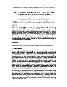
IV. S ENSOR C ONSTRUCTION Typical sensors used in this scenario have the following III. OVERHEAD T RAFFIC characteristics: (a) Transmitter - Transmits the data at various power levels. The GA used to perform Node Selection and Route Selec(b) Receiver - Receives the data targeted towards it. tion is targeted with two competitive objectives running at (c) Power control - Controls the power to be transmitted the sink. The introduction of this layer as a separate protocol according to the function assigned. aids in using the snoop data for predicting the fitness data. (d) Function control - Performs the protocol actions related It is important to note that the sink builds up the Node to the function. These actions are related to identifiDatabase tree by snooping the routed data and the setupcation, advertising, power-control, performing bindings data (Initialization Step) consisting of Node ID, Transmission and associations with other nodes, and sensing, etc. Distance (to ICR and other neighboring nodes), associated CH (e) Test control - Performs the test functions. Test control is and routes to the sink (primary and fail-over routes). This data transparent to the function control and does not interfere is further evaluated at the sink for the creation of additional with its working. This control is required to simulate a data-points consisting of various fitness categories defined in 3381 This full text paper was peer reviewed at the direction of IEEE Communications Society subject matter experts for publication in the IEEE ICC 2006 proceedings.
future topology while not interfering with the current one. GA will make use of this function to evaluate the fitness before committing this topology to all nodes. (f) Alert generation - Generates an alert action to the sink upon any critical/warning or quantized event (like battery depletion). (g) Memory - Limited memory is required to collect the data payload related to sensing, test-data, or routequeues. These characteristics are required for proper functioning of the self-organizing sensor network using genetic algorithms. Most of these characteristics are related to the functional adaptation of the sensor based on function allocation by the sink without interrupting the sensing operation. Function SN, CH, ICR
A L E R T
Test SN, CH, ICR
Fig. 5.
TX M E M
RX
Illustration of sensor construction.
(a)
Fitness
1.5 1
CHF
0.5
NCF BF
0 0
30 60 90 Generations (x10)
Total Fitness
V. N UMERICAL R ESULTS Experimental setup consists of 100, 225, 400, 625 nodes placed at random positions in a 30 × 30 space. Each of the nodes picks up a random coordinate between (0, 0) and (30, 30) and assigns itself an UUID and a random battery capacity between 0 and 15. Once all the nodes have placed themselves in the listen mode, GA is run with the following parameters: • Population size = 0.75(number of nodes) • Crossover rate = 0.8(n − point cross-over) • Mutation rate = 0.004 • Number of generations = 1000. The experiment is simulated in an environment where each node acts as a Linux thread. Once GA run has completed, it assigns a function to each of these threads. These threads then start acting as independent nodes and initiate the node specific protocol. Each of these independent threads is capable of simulating battery depletion and transmission energy. In the experiment, it is assumed that there are no obstructions in the sensor transmit/receive path. (b)
1 0.8 0.6 0.4 0.2 0
625 400 225 100 0
30 60 90
Generations (x10)
Fig. 6. (a) Fitness chart for CHF/NCF/BF for 100 nodes; (b) Total fitness chart for 100, 225, 400, and 625 nodes setup (right).
and battery fitness increase monotonically with the number of generations. The same is true for the total fitness (Fig. 6(b)), which is a function of all the individual fitness. Also, as seen in Fig. 4, complete connectivity between non-extinct nodes and the sink can be maintained until 65% of the nodes die. While the death of sensors will reduce the coverage, the presence of efficient routing will reduce the number of orphan nodes. VI. C ONCLUSION In this paper we have presented a novel approach to design a self-organizing network based on genetic algorithms. Sensors that are placed at random are assigned functions (sensing node, cluster-head, router, or inactive-node) based upon the results of GA. The GA approach optimizes the network to maximize energy usage along with battery conservation with route optimization. It can be shown that the periodic run of a genetic algorithm will help conserve the overall energy of the system with maximum operability. As it can be seen from Fig. 6(b), individual components tend towards maximizing their fitness with the passing generations in a uniform manner. That shows that the goal of maximizing the system fitness along with individual component fitness can be achieved with a considerably reduced complexity. The algorithm also prevents the over-optimization of an individual fitness component at the cost of other components. One of the challenges in GA is to be able to converge in the shortest time possible. As an extension of this paper, we will show the applicability of demand-based, mixed model where we run GA until convergence and then run traditional algorithms (e.g., TABU, directed diffusion, etc.) to achieve the target fitness. We will also research the prediction of system usage and the resulting topologies based on historical trends. The derivatives of these trends can then be used to define an individual fitness along with the current fitness parameters which will improve upon the uniform sensor-node usage assumption. As a part of future research, we will continue to work on improvements related to the security and the corresponding overhead. We also plan to address the challenges involved in the identification of domain boundaries in large networks which can be partitioned into multiple small network domains capable of performing GA. R EFERENCES [1] I. F. Akyildiz, W. Su, Y. Sankarasubramaniam, and E. Cayirci, “Wireless sensor networks: a survey,” Computer Networks, vol. 38, pp. 393–422, Mar. 2002. [2] K. Akkaya, M. Younis, “A Survey on routing protocols for wirelsss sensor networks,” Ad Hoc Networks, vol. 3, pp. 325–349, May. 2005. [3] R. Min, M. Bhardwaj, S.-H. Cho, E. Shih, A. Sinha, A. Wang, and A. Chandrakasan, “Low power wireless sensor networks,” in Proc. Int. Conf. VLSI Design, Bangalore, India, Jan. 2001. [4] J. M. Rabaey, M. J. Ammer, J. L. da Silva, Jr., D. Patel, and S. Roundy, “PicoRadio supports ad hoc ultra low power wireless networking,” IEEE Computer, vol. 33, pp. 42–48, July 2000. [5] R. H. Katz, J. M. Kahn, and K. S. J. Pister, “Mobile networking for smart dust,” in Proc. 5th Annual ACM/IEEE Int. Conf. Mobile Computing and Networking (MobiCom’99), Seattle, WA, Aug. 1999. [6] P. Pardalos and H. Wolkowicz, “Quadratic assignments and related problems,” DIMACS Series in Discrete Mathematics and Theoretical Computer Science, vol. 16, 1994. [7] D. Fudenberg and J. Tirole, Game Theory, MIT Press, 1991. [8] D. Goldberg, Genetic Algorithm in Search, Optimization and machine learning, Addison-Wesley Publishing Company, Inc., 1989. [9] J. Horn, J, N. Nafpliotis, and D. Goldberg, “A niched Pareto genetic algorithm for multiobjective optimization: Evolutionary Computation,” in Proc. 1st IEEE Conf. Computational Intelligence, pp. 82–87, 1994. [10] Q. Li, J. Aslam, and D. Rus, “Hierarchical power aware routing in sensor networks,” in Proc, DIMACS Workshop on Pervasive Networking, 2001.
As seen in Fig. 6(b), convergence points are dependent upon the number of nodes being optimized. In all four cases convergence is reached within the first 500 generations. After that point improvement in the fitness is minimal. We can call this an 80% fitness point. After this point we may use a deterministic approach to achieve further fitness. As seen in Fig. 6(a), cluster-head fitness, node-communication fitness, 3382
This full text paper was peer reviewed at the direction of IEEE Communications Society subject matter experts for publication in the IEEE ICC 2006 proceedings.