data are used to test the performance of this classification .... Testing signal sequence after filtering. Fig. .... [2] C. M. Scala, âA semi-adaptive approach to in-flight.
Self-Organizing Map Neural Network for Transient Signal Classification in Mechanical Diagnostics* Haoying Sun, Mostafa Kaveh, Ahmed Tewfik Department of Electrical and Computer Engineering University of Minnesota 200 Union St. SE, Minneapolis, MN
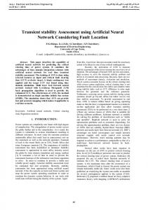
ABSTRACT Acoustic Emissions (AE), generated by the formation and growth of micro-cracks in metal components, provide us with a promising mechanical fault detection technique in monitoring complex-shaped components in helicopters and aircraft. A major challenge for an AE-based fault detection algorithm is to distinguish crack related AE signals from other interfering transient signals, such as fretting related AE signals and electromagnetic transients. In this paper, we presents a classifier, which makes its decision based on the features extracted from joint time-frequency distribution data by Self-Organizing Map (SOM) neural network. In-flight data are used to test the performance of this classification system, with promising results.
1. INTRODUCTION Acoustic Emissions (AEs) are ultrasonic waves emitted from material deformation process, such as micro crack generation and growth. These AEs can be detected by the piezoelectric transducers (PZT) placed close to the AE sources. Thus AE based nondestructive inspection technique provides an attractive automatic fault monitoring method in helicopter and other aircraft. The characteristics of AE signals due to crack generation and growth have been extensively studied in recent year [1]. Most of these studies have been done in isolated metal specimen under controlled laboratory environment. However, in practice, the crack-related AE signal has to be detected when the helicopter is in operation. In this case the crack related AEs are measured in the presence strong interference and noise. These interference and noise, caused by vibration, fretting, electromagnetic and many other factors are very complex and highly nonstationary. AEs from crack generation and growth have possible frequency components up to several MHz, whereas vibration signals occur below 100kHz [2]. Thus vibration noise can be removed by prefiltering. However other
* This work was supported by the office of naval research under MURI contract N00014-95-1-0539. Many thanks to Honeywell Inc., Minneapolis, for their kind permission to use their data.
Interference such as fretting caused by rubbing of parts and electromagnetic noise are also transients and similar to crack related AE in both time and frequency domains. Then the discrimination of crack related AE from other interference transients becomes an important issue and needs considerable attention from a signal processing point of view. This classification problem is further complicated by the fact that in complex metal component geometry the characteristics of AEs are not known a prior. Besides, the noise and interference are highly load and component dependent [3]. It is nearly impossible to use a conventional statistical classifier, to the extent it needs the accurate mathematical models of the signals, to distinguish the crack related AE from other interference transients. In contrast, the neural network classifier seems very suitable in this transient classification problem because it does not need the accurate model about the signals and it has strong non-linear mapping capability. Previous research has shown that temporal information, i.e., time of arrival and rise time of the transients during a period of rotation cycles of the rotor, can be used to distinguish crack related AE and other interference [3][4]. However, the classification scheme based purely on temporal information is inadequate in a highly noisy environment such as the operating helicopter’s rotor. Our investigations, over the past four years, suggest that the spectral components also bear valuable information for the discrimination of the crackrelated AE from other interference. Thus, it is quite natural for us to design a classifier based on joint time-frequency distribution data. In this paper, we present a direct transient signal classifier based on a Self-Organizing Map (SOM) neural network. In the proposed system, we do not need to add a detection stage before the classification. The basic idea is to use the SOM neural network to map high dimensional time-frequency distribution data into a low dimensional codebook. Then the output from the SOM is used to make the classification decision. In-flight helicopter data provided by Honeywell has been used to test the performance of this neural classifier. The paper is organized as follows. In Section 2, we present the inflight transient signal acquisition system as well as the
collected data. In Section 3 we give the classification system structure and how to use the SOM to do transient classification. The classification results are also given in Section 3. Section 4 summarizes the paper and proposes future research topics.
2. In-Flight Transient Signal Acquisition System The Rotor Acoustic Monitoring System (RAMS) developed by Honeywell was flight-tested at Patuxent River Naval Base on CH-46 Sea Knight helicopter from August 28 to September 18, 1997 [8]. More than 16 hours of flight data was recorded from 8 piezoelectric sensors mounted on one of the rotor arms. The eight sensor positions are shown in the Fig. 1. Sensors 1, 2 and 3 are located on the connection link, sensors 4 and 5 on the pitch shaft, and sensors 6, 7, and 8 on the pitch housing. A piezoelectric pinger is mounted on the connection link of the rotor arm to simulate micro-crack generation. Whenever the pinger is ON, a small pressure proportional to the control voltage is added to the connection link. When the pressure is released, an acoustic transient signal is emitted from this area. Crack generator
8 6
In this paper, we use the data collected from sensor 2 at excitation voltage of 100V only since sensor 2 is located at the same connection link as the pinger. Sensor 3 is also located at the same component. However, its data was corrupted at the time of data recording and could not be used. Although sensor 1 is also mounted at the connection link, it is further away from the pinger than sensor 2 and 3. The signal energy drops quickly in sensor 1. Thus we will only use the data from sensor 2 in this paper to test the performance of our neural classifier. All the other sensors are mounted on different components from the pinger. A more sophisticated method is needed to detect acoustics emission signal before any classification methods can be used.
3. Transient Signal Classification System Based on the SOM Previous work conducted by our group has verified that timefrequency decomposition is well-suited for the detection and classification of AE signals [5] [6]. The responses of sensors to a crack related AE signal and extraneous interference have different arrival times and different frequency contents. These differences are due to propagation effects in mechanical parts. We propose our transient classification system structure as shown in Fig. 2.
7
3 2
4
5
1
Fig. 1 Sensor position at in-flight data acquisition system Honeywell provided us with a digitized set of data from the level flight. The data includes the recordings at all eight sensors for all eight permutations of pinger ON/OFF and pinger control voltages of 100V, 48V, 20V and 10V case. Different pinger excitation voltages simulate the different micro crack sizes, from a small crack (voltage 10V) to a large crack (voltage 100V). However the digitization of the data for the different channels of observation was not synchronized, i. e., the data digitized at different channels were all from different time segments. The duration of each digitized segment of data was about 2 seconds at a sampling frequency of 2MHz (12 bit A/D accuracy).
Fig. 2 Transient Classification System Block Diagram During the prefiltering/preprocessing stage, after A/D conversion, we conduct bandpass filtering to remove most of low frequency vibration noise (lower than 50 kHz) and high frequency components (higher than 300KHz), which carry no useful information in the Honeywell data. Then we apply
Short-time Fast Fourier Transform (SFFT) to the time-domain signal to obtain the signal. This results in a sequence of frequency decomposition vectors extending along the time axis. This high dimensional spectrogram matrix is then fed into the SOM neural network and the low dimensional SOM codebook matrix is obtained. The final stage is to make classification decision based on the SOM outputs.
We applied the above classification system to the in-flight data acquired from the system described at Section 2. A sample segment of data after bandpass filtering from sensor 2 at pinger excitation voltage level of 100V is shown in Fig. 3, and its spectrogram representation is shown in Fig. 4.
locations of the active neurons to different input pattern tend to become ordered. Thus the spatial location of a neuron in the neural network can represent a particular input signal domain. As shown in the Fig. 5, the SOM network takes the form of grid structure. The grid vertices are called neurons, whose weight vectors have the same dimension as the input training vector. When the training process starts, the SOM takes the neuron with the minimum distance or most similar to the input vector as the winner. Then the SOM updates the weight vector adaptively in the neighborhood of the winner neuron. When the training process ends, all the input vectors are mapped onto different neurons’ weight vectors called a codebook. Input X
Testing signal sequence after filtering
SOM mapping layer
Winner-takeall layer
Winner index
Fig. 5 Self-Organizing Map neural network Fig. 3 A segment of time domain signal from sensor 2
with time frequency vector as input
specgram of testing signal 1
There are several ways to define the distance measure between the input vector and neurons’ weight vectors such as Euclidean distance and inner product. Here we have used a simple Euclidean distance. The training steps of the SOM network are:
0.9 0.8
pinger transient
frequency, MHz
0.7 0.6
interference
0.5
1.
0.4 0.3
Initialize the SOM. Randomly assign small values to the weight vector of each neuron:
Wi = [m1 , m2 ,
0.2
L , m ], i = 1, 2,L, M × N n
0.1
Here the input signal is a series of n×1 spectrogram vectors as shown in the Fig. 4.
0 0
20
40
60
80 100 120 time elapse, ms
140
160
180
200
Fig. 4 Spectrogram of a segment of data from sensor 2
2.
3.1 Feature Extraction by SOM
L
Provide a new input vector X = [ x1 , x2 , , xn ] , then calculate the distance between each neuron and the new input vector: n
The concept of Self-Organizing Map (SOM) neural network was introduced by Kohonen in early 1981 [7]. The SOM is a sheet like neural network with M×N neurons. Each neuron or a neighboring group of neurons responds to a specific kind of input pattern. After the competitive learning process, the
D j = X − W j = ∑ ( xi − w ji ) 2 , j = 1, 2, i =1
3.
L, M × N
Select the neuron j* as winner so that the Dj* is the minimum among Dj, i.e.,
j* = arg min D j , j = 1,2, j
4.
L, M × N
neurons to each input data set to discriminate between crackrelated AE and other interference transients.
Update the weight vectors of the winner neuron j* and its neighboring neurons adaptively:
Wi (n + 1) = Wi (n) + η (n)[ X (n) − Wi (n)], i ∈ S j (n) or Wi (n + 1) = Wi (n),
i ∉ S j (n)
where Sj(n) is the neighborhood of the winner neuron j* at time instance n. The initial Sj(n) can be large enough to include all the neurons in the SOM. After hundreds of training steps neurons show an ordered pattern, and Sj(n) can eventually shrink linearly to include only one winner neuron j*. η(n) (0