Sensorless AC Current Control with Backstepping Design for a PWM AC-DC Converter B. Bourahla1, B. Mazari1, S. Moreau2, G. Champenois2 1
University of Sciences and technology of Oran, Algeria Faculty of Electrical engineering B.P 1505 El M’naouer, 31000 Oran-Algeria 2 LAII – University of Poitiers, 40 avenue du Recteur Pineau, 86022 Poitiers cedex, France e-mail :
[email protected];
[email protected];
[email protected],
[email protected]
Abstract. In this paper, a novel sensorless AC current control scheme is proposed for the design of PWM AC-DC converter. This design strategy deals with nonlinear backstepping controllers and AC current observer to achieve the purpose of current following. In general, PWM AC-DC converter design requires AC current measurement to achieve control goals, the backstepping observer employed estimates the AC current, and then nonlinear controllers based on backstepping design algorithm are developed to realize the sensorless AC current for the PWM AC-DC converter system. The proposed control scheme is not only to stabilize the PWM AC-DC converter system, but also to drive the current tracking error to converge to zero asymptotically. Furthermore, some simulation results are shown to illustrate excellent performances of the nonlinear backstepping control design scheme applied to a PWM AC-DC converter. Key words: Backstepping control; Backstepping observer; PWM AC-DC converter; sensorless.
1.
Introduction
Three phase AC-DC converters are widely used in industrial applications. Static power converters are nonlinear in nature and consequently generate harmonics into the supply. As a result, the power factor of the converters is usually poor and varies with the load. Most electrical systems are designed on the fundamental frequency [10]. Many research results focusing on the control of AC-DC converters have been reported [1]-[10] such as the adaptive backstepping controller and the feedback linearization technique applied to control the output voltage of three phase AC-DC PWM converter [1]-[2] with and without LCL input filters [7]. Different nonlinear techniques were also applied to converters in electric power networks such as DC/DC series resonant converter and three-phase three-level neutral point clamped rectifier [4]-[5]-[6]. Nonlinear backstepping control [8]-[9]-[11] is a newly developed systematic design method. The most appealing point of it is to use the virtual control variable to make
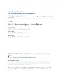
the high-order system simple and thus the final control outputs can be derived step by step through appropriate Lyapunov functions. The design of PWM AC-DC converter systems, in general, requires input current for AC-DC converter measurement to achieve control targets, but lots of PWM AC-DC converter systems do not have AC current [3][12]-[13] or AC voltage [14]-[15] or DC voltage measurement devices. Eliminating AC current or AC or DC voltage sensors simplifies the structure of the driver system. In this paper, with the proposed backstepping AC current observer, a nonlinear backstepping control design scheme is developed for the current tracking control of PWM ACDC converter that has exact model knowledge. The asymptotic stability of the resulting closed-loop system is guaranteed according to Lyapunov stability theorem. As a result, the proposed nonlinear backstepping control design without the use of current sensor is not only to stabilize the AC-DC converter system, but also to force the current tracking error to converge to zero asymptotically. The remainder of this paper is organized as follows. In section 2, the dynamic model of a PWM AC-DC converter is introduced with some important system properties. The sensorless backstepping control scheme consisting of an AC current observer and current input controllers are developed in Section 3 for the purpose current tracking. The simulation results are illustrated in Section 4, and some concluding remarks are given in Section 5. 2. Mathematical model of PWM AC-DC converter Figure 1 represents the topology of the converter under study. The dynamic model of a PWM AC-DC converter can be described in the well known (d,q) frame through the Park transformation [1]-[2] as follows:
i&d = i&q = v&dc =
R L R L
id + ωiq + iq - ωid + 2
3Cvdc
(E i
d d
1 L
V&1 = e e&
( E d - vd )
(E L 1
q
d d
E v R 2 V&1 = -k 1 e + e k 1 e - id + ω i%q +iˆq + d - d (5) d d d L L L
(
- vq
)
)
vdc
selected by
CRL
vd = L k e + ωiˆq + Ed
+ Eq iq -
(1)
At this point, the d -axis voltage control input vd can be
Where id and iq are ( d,q ) axis currents , Ed and Eq are ( d,q ) axis source voltage, vdc is the DC output voltage, vd and vq are ( d,q ) axis converter input voltage . R and L mean the line resistance and inductance, respectively, RL is the load resistance. idc iL R
Ea
L i v a
Eb
ib
Ec
ic
)
ic
(
)
1 d
(6)
Where k is a positive design constant, so (5) becomes 1
R 2 (7) V&1 = - k + e + ωi%q e 1 d L d Step 2: the purpose of this control design is to achieve the reference voltage tracking, so the second regulated variable is denoted by e = vdc - vdcref (8) Where vdcref is the reference signal of DC voltage.
a
vb vc
+ C v dc RL −
Hence, the derivative of (8) is calculated as v 2 2 e& = Ed id + Eq iq - dc - v&dcref 3Cvdc 3Cvdc CRL
(9)
By defining the error variable eq = iq - iqref , where iqref is the stabilizing function chosen as follows: Fig. 1 AC/DC PWM converter topology
3.
Sensorless backstepping control
Since the current measurement of the input AC-DC converter is usually unavailable, an AC current observer must be employed to estimate the actual AC current .Hence, the AC current estimation error is defined by:
i%d = id - iˆd
Where iˆd is the estimate of id and iˆq is the estimate of
iq . Now, we employ backstepping schemes to design the nonlinear controllers with the AC current observer, the backstepping design procedure consists of three steps: Step 1: First of all, since the current id must be forced to be zero, the first regulated variable is selected as ed = id (2) The derivative of (2) is computed as E v R e&d = i&d = - id + ωiq + d - d (3) L L L The first Lyapunov candidate V1 is chosen as
1
e
2 d
2 The derivative of (4) is computed as
1
-Ed id + Eq
+ v&dcref CRL
3Cvdcref vdcref 2
(10)
(9) can be rewritten as 2 2 2 e& = Eq eq + Eq iqref + Ed id 3Cvdc 3Cvdc 3Cvdc
vdc
-
- v&dcref
CRL 1
e& = -
i%q = iq - iˆq
V1 =
iqref =
e+
2
Eq eq (11) CRL 3Cvdc With the choice of the second Lyapunov candidate 1 2 V2 = k e (12) 2 2 Where k 2 a positive design constant, the derivative of (12) is is computed as V&2 = k ee& 2
V&2 = -
k
2
2k
2
e +
CRL
2
Eq eq e
3Cvdc
(13)
Step 3: The derivative of the given error variable eq is computed as e& = i& - i& q
q
e&q = -
(4)
-
qref
R L
iq - ωid +
3C 2Eq
2 v&dcref -
Eq L
3C 2Eq
-
vq L
+
Ed ded Eq dt
vdcref v&&dcref .
-
3 E q RL
vdcref v&dcref (14)
Therefore, by following the choice of (4) and (12), the complete Lyapunov function candidate is selected as 1 2 1 2 V = V1 +V2 +V3 + i%d + + i%q , (15) 2γ1 2γ2 Where γ 1 , γ 2 are the positive adaptation gains. From (7) and (13), (14), the derivative of (15) is computed as follows; 1 1 V& = V&1 +V&2 +V&3 + i%d i&%d + + i%q i&%q (16) γ1 γ2 R 2 k 1 1 2 2 V& = - k + e - 2 e - k eq + i%d i&%d + + i%q i%&q 1 3 d L CRL γ1 γ2
+ eq k eq 3
3
-
Eq RL
R L
iq - ωid +
vdcref v&dcref -
+ ωi%q e d
+
2k
2
3Cvdc
3C 2Eq
Eq L
-
vq
+
L
2 v&dcref -
Ed ded
2Eq
vdcref v&&dcref
+
3
R L
iˆq - ωiˆd +
Eq
-
vq
L
2k +
L
2
3Cvdc
Clearly, V& in (21) is negative definite, so it implies that the resulting closed loop system is asymptotically stable and, hence, all the error variables ed , e and eq and the
(17)
At last in order to make the derivative of the complete Lyapunov function (16) is negative definite, the direct axis voltage control input and the voltage adaptation law are chosen as follows:
2k E R R 2 v q = L k eq + Eq e - iˆq - ω + d iˆd 3 3Cvdc L Eq L
iˆd =
2Eq
vdcref v&&dcref
(18)
E v ωiˆq + d - d L L ( L + R ) L
- ωeq +
will
converge
to
γ1 (19) Eq L
Ed R
zero
asymptotically. Therefore, the d -axis current iˆd will converge to zero and the DC voltage will converge to the reference output voltage for PWM AC-DC converter. In addition, because ed and eq can converge to zero, the
iL
Ea
R
L i v a
Eb
ib
Ec
ic
ic a
+ C −v dc RL
vb vc
abc dq
PWM
abc
OBSERVE
vdc vdcerf
iˆq iˆd E q E d
vd
dq vq
CONTROLLER
Fig. 2 The block diagram of AC current tracking design scheme
Eq Ed 3 3C 2 k ed vdcref v&dcref v&dcref 1 L Eq E q RL 2Eq 3C
i&%d , i&%q
error
idc
R E +ωed - eq + d ω L Eq
ω γ2
Eq
Eq e
1 Rˆ Ed v d & - id + ωiˆq + - - i%d 2Eq L L γ1 L E q vq & 1 R E R -ωeq - d + i%q - iˆq - ωiˆd + - i%q Eq L L L γ2 L
−
L
Ed
eq +
Therefore, substituting (18), (19) and (20) into (17), we are able to obtain R 2 k R 2 R 2 2 2 V& = - k + e - 2 e - k eq i%d i%q (21) 3 γ1 L γ2 L 1 L d CRL
vdcref v&&dcref + i%d
+
R
(20)
Ed R 3 3C 2 Ed vd Eq vq vdcref v&dcref v&dcref - iˆd +ωiˆq + - + L L L Eq L L Eq RL 2Eq 3C
+ ωed −
estimated input current for AC-DC converter will converge to the actual real input current in the primary side of the converter.
Eq eq e
R 2 k R 2 R 2 2 2 i%d i%q V& = - k + e - 2 e - k eq 1 d 3 L CRL γ1 L γ2 L +eq k eq -
Eq vq -ωiˆd + L L ( L + R ) L
estimation
Eq dt 3C
iˆq =
4. Simulation results In our simulations, the system parameters and design constants of the PWM AC-DC converter are given in Tables I and II, respectively.
Table I PWM AC-DC Converter system parameters Supply’s voltage and frequency
220V,50Hz
Line’s inductor and resistance
0.1mH,2mΩ
DC link resistance
20Ω
Output capacitors
370µF
PWM carrier frequency
1kHz
Table II Control Design Constants
k1
k2
k3
γ1
γ2
10000
1
70
1
1
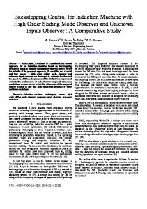
The voltage transient responses are chosen in the following two cases: Case I: DC voltage reference changes from 250Vto 350V and back to 250V. Case II: load changes from 20 Ω to 10 Ω.
From the simulation results, it is obvious that the proposed sensorless backstepping controllers are quite successful and efficient for the PWM AC-DC converter current tracking control.
5.
In this paper, we have implemented and simulated the backstepping control and AC current observer which provide an efficient control design for both tracking and regulation, The resulting closed-loop system is guaranteed to be asymptotically stable, and the AC current tracking error and the AC current estimation error are able to converge to zero asymptotically according to Lyapunov stability theorem. In addition the simulation results have clearly illustrated that the proposed nonlinear backstepping controllers are quite effective and efficient for the PWM AC-DC converter current tracking control without the need of current sensors. The strategy control was very robust to uncertain parameters and gave a very high power factor and small ripple in the current line supply.
References [1]
The sensorless backstepping control with AC current observer is used in our comparative simulations. Fig.3 and 4 illustrate respectively the simulation results of voltage transient responses for DC voltage reference and for load changes. The fig.3a and fig.4a show the voltage tracking response of the reference and real output DC voltage in the case of DC voltage reference and load changes and the error between them. The fig.3b and fig.4b show the supply voltage and current in the primary side, the AC current estimated id and iq and the error between the estimated currents and reference currents in cases I and II, respectively. It can be seemed from fig.3a and fig.4a that the actual DC voltage responses can track the reference DC voltage in the beginning when the reference DC voltage is an exponential lick signal. From the DC voltage tracking simulation results in fig.3b and fig.4b, we can find that the estimated AC current with backstepping controllers have excellent performances. The error between real DC voltage and reference DC voltage can converge to zero asymptotically. Therefore, the estimated AC current are able to converge to the references current. The direct axis current id estimated is always forced to zero in order to correct and maintain to unity the primary power factor between source current and source voltage .The q axis current iq estimated will approach a constant when the actual DC voltage reaches the reference DC voltage. Finally, we can find that the (d,q) axis current errors between estimated ones and the references can converge to zero asymptotically. From the comparison of DC voltage tracking simulation results shown in fig.3b and fig.4b, it is clear that the estimated AC current with backstepping controllers have excellent performances. The direct axis current estimated is always forced to be zero as we have already expected.
Conclusion
[2]
[3]
[4]
[5]
[6]
[7]
[8]
[8] [10]
[11]
[12]
[13]
D.C.Lee,G.M.Lee,and K.D.Lee, “DC-bus voltage control of three –phase AC/DC PWM converters using feedback linearization ,”IEEE Trans.Ind.Appl.,Vol.36,no.3, pp.826-833,May/Jan.2000. D.C.Lee, K.D.Lee,and G.M.Lee, “Voltage control of PWM converters using feedback linearization,”IEEE Trans.Appl.confe,.2, pp.1491-1496,.1998. D.C.Lee,and D.S.Lim, “AC voltage and current sensorless control of three-phase PWM rectifiers,”IEEE Trans.Power Electronics.,Vol.17,no.6, pp.883-890,Nov.2002. L.Yacoubi,F.Fnaiech,L.A.Dessaint,and K.A.Haddad, “Adaptive nonlinear control of a three-phase three-level neutral point clamped rectifier,”Proc.IEEE.Ind.Appl.confe.US,.pp.619625,.2001. L.Yacoubi,F.Fnaiech,K.A.Haddad,and L.A.Dessaint, “Input/Output feedback linearization control of a three-phase three-level neutral point clamped boost.rectifier,”Proc.IEEE.Ind.Appl.confe.US,.pp.626-631,.2001. L.Yacoubi, K.A.Haddad,F.Fnaiech,and L.A.Dessaint, “A DSPbased implementation of a new nonlinear control for a three-phase neutral point clamped rectifier,”IEEE.Trans.Ind.Elec.,Vol.52.no 1,pp.197-205,Feb 2005. D.E.Kim,and D.C.Lee, “Feedback linearization control of threephase AC/DC PWM converters with LCL input filters,”IEEE.the 7th International Converence on Power Elec.,pp.766-771,Oct 2226,2007. J.Zhou,and Y. Wang, “Adaptive backstepping speed controller design for a permanent magnet synchronous motor,” Proceedings of the IEE Electron Power Application, Vol. 149,no. 2,pp. 165172, 2002 M.Krstié,I. Kanellakopoulos, and P.Kokotovié, nonlinear and adaptive control design , John Willey and Sons, Inc. 1995 A.Allag,M.Y.Hammoudi,S.M.Mimoune,and M.Y.Ayad, “Adaptive backstepping voltage controller design for an PWM AC-DC converter,” International Journal of Electrical and Power Engineering 1, 1,pp. 62-69, 2007 S.S.Ke, and J.S.Lin,“Sensorless speed tracking control with backstepping design scheme for permanent magnet synchronous motors,”Proc.IEEE.Conf.Cont.Appl. Toronto,Canada,pp 487492,Aug 28-31,2005. C.T.Pan,“Modeling and analysis of a three phase PWM ac-dc converter without current sensor,”Proc.Inst.Elect.Eng.B,Vol.40,Mar.1993. W.C.Lee,D.S.Hyun,and T.K.Lee,“ A novel control method for three-phase PWM rectifier using single current sensor,”Proc.IEEE.PESC.Conf.,Charleston,SC,pp.515-520,1999.
[14] T.Takeshita,T.Kobayashi,and N.Matsui, “ A scheme of power source voltage sensorless three-phase PWM ac/dc converter, ”Trans.IEE Jpn.,vol.114-D,no.12,pp.1211-1219,1994. [15] T.Ohnuki,O.Miyashita,P.Lataire, and G.Maggetto,“ A three-phase PWM rectifier without voltage sensor,”Proc.EPE 97 Conf.,pp.2.881-2.886,1997.
[16] B. Bourahla: “ Commande Scalaire de la Machine Asynchrone en Temps Réel, Etude et Réalisation » Master thesis, june 21th , 2008, USTO-MB, Oran, Algeria
400
400 DC voltage reference Real DC voltage
350
350
300
300
250
250 Vdc(v)
Vdc(v)
DC voltage reference Real DC voltage
200
200
150
150
100
100
50
50
0
0
0.1
0.2
0.3
0.4
0.5 0.6 Time(s)
0.7
0.8
0.9
0
1
400
0
0.1
0.2
0.3
0.4
0.5 0.6 Time(s)
0.7
0.8
0.9
1
280 DC voltage reference Real DC voltage
380
DC voltage reference Real DC voltage
270
360 340
260 Zoom Vdc(v)
Zoom Vdc(v)
320 300 280 260 240
250
240
230
220 220
200 180 0.28
0.3
0.32 Time(s)
0.34
0.36
210 0.47
0.38
20
20
15
15 Error between Vdc real,Vdc reference (v)
Error between Vdc real, Vdc reference
0.26
10 5 0 -5 -10 -15 -20
0.48
0.49
0.5
0.51 0.52 Time(s)
0.53
0.54
0.55
0.56
10 5 0 -5 -10 -15
0
0.1
0.2
0.3
0.4
0.5 0.6 Time(s)
0.7
0.8
0.9
Fig. 3.a Voltage transient responses for dc-voltage reference changes
1
-20
0
0.1
0.2
0.3
0.4
0.5 0.6 Time(s)
0.7
0.8
Fig. 4.a Voltage transient responses for load changes
0.9
1
250
250 isa vsa
150
150
100
100
50
50
0 -50
0 -50
-100
-100
-150
-150
-200
-200
-250 0.2
0.22
0.24
0.26
0.28
0.3 0.32 Time(s)
0.34
0.36
0.38
0.4
-250 0.4
80
0.44
0.46
0.48
60
60
50
50
40 30 20
0.56
0.58
0.6
20
0
0
-10
-10
0
0.1
0.2
0.3
0.4
0.5 0.6 Time(s)
0.7
0.8
0.9
estimated AC current id estimated AC current iq
30
10
-20
1
40
0
0.1
0.2
0.3
0.4
0.5 0.6 Time(s)
0.7
0.8
0.9
1
40 Error betw een id estimated and id reference Error betw een iq estimated and iq reference
Error betw een id estimated and id reference Error betw een iq estimated and iq reference
30
30
20
20 Error current id, iq (A)
Error current id, iq (A)
0.54
40
10
10 0 -10
10 0 -10
-20
-20
-30
-30
-40
0.5 0.52 Time(s)
70
current id , iq (A)
current id , iq (A)
0.42
80 estimated AC current id estimated AC current iq
70
-20
isa vsa
200
Vsa(v) , isa(A)
Vsa(v) , isa(A)
200
0
0.1
0.2
0.3
0.4
0.5 0.6 Time(s)
0.7
0.8
0.9
Fig. 3.b Voltage transient responses for dc-voltage reference changes
1
-40
0
0.1
0.2
0.3
0.4
0.5 0.6 Time(s)
0.7
0.8
Fig. 4.b Voltage transient responses for load changes
0.9
1