SEMINAR ON ELECTRICAL ENGINEERING, INFORMATICS, AND ITS EDUCATION 2011
1
Sensorless Flux Vector Control of Induction Motor for Driving Centrifugal Pump Aripriharta1, Rini Nur Hasanah2
[email protected],
[email protected] 1. Postgraduate Master Degree in Electrical Engineering, Brawijaya University, Indonesia, 2. Department of Electrical Engineering, Faculty of Engineering, Brawijaya University, Indonesia
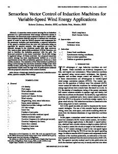
Abstract— This paper presents the implementation of sensorless flux vector control of induction motors in centrifugal pump applications. Unlike the commonly known vector control algorithm, application of this method would not require either speed sensor or position transducer. This algorithm provides low cost application, however it would still offer a good performance. In this project, validation of the algorithm has been done by taking the benefit of the ATV31 module. It has been used to drive a 3-phase squirrelcage induction motor of 0.5HP, 4-pole, 1370 rpm, 50Hz. The motor has been loaded using a magnetic powder brake and operated at variable torque mode in order to represent the true characteristics of centrifugal pumps. Based on the experimental results, it can be concluded that this algorithm is working well to serve loads with variable torque. Keywords: centrifugal pump, variable torque, squirrel-cage, sensorless flux vector control Index Terms f stator input frequency, hertz
V p T
stator input voltage,volt poles number torque, Nm
λds, λqs
d- and q-axis components of the stator flux vector, Wb. initial value components of the stator flux vector, Wb.
λr
λds0, λqs0 Ids, Iqs
rotor flux, Wb
d- and q-axis components of the stator current vector, A
s slip motor speed, rpm Vqsss, V dsss steady-state component of stator voltage vector , volt I.
INTRODUCTION
In order to save energy on centrifugal pump drives, it is becoming more and more common nowadays to replace the throttle control of air flow with variable speed drives (VSD) using three-phase squirrel-cage induction motors. The V/f control or scalar control is the most common Manuscript received on August 15th, 2010. Aripriharta. Postgraduate Master Degree in Electrical Engineering, Brawijaya University, Indonesia and Lecturer at the Department of Electrical Engineering, Malang State University, Indonesia. Phone:+62341-7044470. Rini Nur Hasanah is a Lecturer at the Department of Electrical Engineering, Faculty of Engineering, Brawijaya University, Indonesia.
algorithm used [1],[8]. This control algorithm gives good steady state performances, but if the load torque is suddenly changed, this technique would show poor dynamic performances [1-2],[4],[7-8]. Another disadvantage has been found when the motors must be operated with certain torque at low speed to maintain the airflow because the V/f control also does not suit well. In this operating condition, the machine becomes over heated being caused by the field-weakening phenomenon[8]. To improve the drives performance this method is replaced by sensorless flux vector control, because it can provide excellent control of induction motor, giving superior speed regulation at low speed and better dynamic response [1],[3],[5-8],[11]. In fact, the structure of the sensorless flux vector control algorithm still retains the basic V/f control block [2],[7] for reasonable low cost applications. In this topology, speed sensor or position transducer is not required. The control algorithm improves upon the basic V/f control technique by providing both a magnitude and angle between the voltage and current. Voltage angle controls the amount of motor current that goes into motor flux being enabled by the torque current estimator. By controlling this angle, low speed operation and torque control are improved over the standard V/f drive [7-8]. Thus, the control algorithms can be arranged to minimize the dependence on motor parameters. It does not depend on the inherent speed stability of AC induction motors, as do V/f and open loop flux vector drives, and can be operated in a true torque mode [2],[7]. In fact, many approaches [3-4],[6],[9-11] have been suggested for speed sensorless vector control induction motor drives. These methods are based on the following schemes: harmonic caused by machine saliency, Model Reference Adaptive System (MRAS), Extended Kalman Filter (EKF), artificial neural network (ANN), extended Luenberger observers, instantaneous reactive power. Some of these methods require specially modified machines and the injection of disturbance signals or the use of a machine model. Otherwise, all other methods for speed estimation using a machine model fed by stator quantities are parameter dependent; therefore, parameter errors can degrade speed control performance. Thus, some kind of parameter adaptation is required in order to obtain high-performance sensorless vector control drive [3],[6],[9]. In this paper, we introduce the real implementation of a sensorless flux vector control algorithm which has been used to control an induction motor driving centrifugal
SEMINAR ON ELECTRICAL ENGINEERING, INFORMATICS, AND ITS EDUCATION 2011
pump. To test the validity of the proposed algorithm, in this project we used an ATV31 module, which drives a virtual variable torque load by controlling the shaft speed of a 0.5hp three-phase squirrel-cage induction motor.
2
constant flux. As a result, the motor will be unable to supply rated torque. The load’s torque requirements increase while the motor’s ability to supply torque decreases [12]. B. Sensorless Flux Vector Control Vector control techniques can be separated into two categories: direct and indirect flux vector orientation control schemes. For direct control methods, the flux vector is obtained by using stator terminal quantities, while indirect methods use the machine slip frequency to achieve field orientation [3-4]. In [5-7], the sensorless flux vector algorithms are based on the principle of field orientation, which states that if the current vector is controlled relatively to the rotor flux vector then the magnitude of the flux vector and the motor torque can be independently controlled. Moreover, as mentioned in [2], the flux vector control has been enhanced to allow the drive to operate without the use of a speed feedback device, relying instead on estimated values for speed feedback and slip compensation.
II. CENTRIFUGAL PUMP DRIVES
A. Drives Requirement Variable torque is the most common load type. Typical application of such this kind of load can be found in centrifugal pumps [2-3], [7],[10]. The characteristic of this load is illustrated in Figure 1. The torque is quadratically, and the power is cubically proportional to the speed. The speed on a pump is increased by increasing the ac drive frequency applied to the motor. Torque is affected by flux and working current. The drive will maintain appropriate flux by adjusting the voltage and frequency ratio dependent on speed [10].
Figure 2 shows the control scheme of this algorithm. This control scheme retains the v/f core and adds additional blocks around the core to improve the performance of the drive. A current resolver attempts to identify the flux and torque producing currents in the motor and makes these values available to other blocks in the drive. A current regulator that more accurately controls the motor replaces the current limit block. Notice that, the output of the current regulator is still a frequency reference [2].
Figure 1. Characteristics of a typical centrifugal pump Torque Current Estimate
Current Feedback Current Resolver
+10V
Flux Current Estimate
Torque Current Ref. Speed command
V mag Current Regulator
Speed Regulator
Voltage Control
Voltage Vector
I.M
V angle
V/Hz Control
Inverter
C-pump
0 Auto Tune Parameters Electrical Frequency Estimated Speed
Slip Estimator
Torque Current Estimator
Figure 2. Sensorless flux vector algorithm Furthermore, during acceleration, working current will increase causing a corresponding increase in torque. In this application, torque increases in proportion to the speed squared. This is due to the increase in hydraulic head as the pump works harder to pump more fluid. Beside that, horsepower increases in proportion to the speed cubed due to an increase of torque and speed. The pump cannot be operated above the rated frequency of the motor because the drive will no longer be able to provide
For detail understanding of sensorless flux vector control technique, let us consider the mathematical expression of several important blocks in Figure 2. Note that all equations that introduced in this paper are based on [7]. In the rotor flux oriented reference frame, the equations for rotor flux magnitude and torque are shown in equation (1) and (2). The rotor flux is a low pass filtered mirror of the stator current component oriented
SEMINAR ON ELECTRICAL ENGINEERING, INFORMATICS, AND ITS EDUCATION 2011
with it and the torque is the product the rotor flux and the stator current orthogonal to it. .
=
(1)
3 n
T= . (I qs.λds-I ds.λqs) 2 2
(2)
Torque is estimated using Eq. (2), whereas the speed or slip estimation block is realized using Eq. (3). Therefore, if Eq. (1) is kept as well as the aligned slip frequency equation, Eq. (2), then the motor currents must be oriented to the rotor flux[7].
ω =
.
(3)
Thus, as mentioned before, the flux vector is directly measured from the terminal electrical quantities of voltage and current. Equations (4) to (7) are continuously integrated and solved to give an instantaneous measurement of the stator and rotor flux vector. These are used in the flux estimator block. The inputs to these equations are the stator voltage and current vectors. The current vector is best directly measured but the voltage vector can be deduced from a DC link voltage measurement and the PWM switching pattern in Control voltage block [2],[5],[7]. stator flux: t
λqs= ∫0 Vqs-Rs.I qsdt+ λqs0 t
λds= ∫0 Vds-Rs.I dsdt+ λds0
(4)
λdr =
λqs-
λds-
.
(
)
.
(
)
The motor model block can calculate a steady state voltage vector command based on the d- and q-axis current commands using Eq. (8) and Eq. (9). This block also includes the d- and q-axis current regulators and a rotor mechanical speed estimator based on the aligned slip using Eq. (10).
V ss = R .I
+ ω.
V ss = R .I ω =
Lm Lr
.R .
.
(
+ ω.
)
.
.I
(
+ ω. )
.I
λ
(8)
(9) (10)
The current regulator block (see Figure 2) converts a voltage vector command into gate command signals for the inverter. To accomplish this it samples the DC link voltage real time to determine the instantaneous duty cycles for each phase. It also controls the sampling of the phase currents and passes the actual voltage and current vector measurements to the flux estimator. In the inner part of the scheme, it can be seen that the flux regulator (inside the current resolver on Figure 2) generates the d-axis current command through a PI regulator by comparing the commanded to the measured rotor flux. This eliminates the need of having an accurate estimate of magnetizing inductance. The torque command is converted to a q-axis current command using the aligned torque in Eq. (2). If higher accuracy is required, comparing the calculated torque from the flux estimator with the commanded torque can generate a correction.
(5) III. LABORATORY EXPERIMENT
rotor flux:
λqr =
3
.I qs
(6)
.I ds
(7)
The primary output of the flux estimator is the rotor flux vector given as the q- and d-axis Cartesian components. This is the input to the flux vector orientation block, which generates the instantaneous orientation and rate of rotation of the flux vector. Thus, the flux vector orientation block uses a phase-locked loop to track the flux with a smoothly rotating vector. This produces a reference frame aligned with the rotor flux vector. Another advantage of a phase-locked loop is that the flux vector can be smoothly tracked through zero speed, where the flux estimate is unreliable, due to the inherent memory of the PI tracking regulator and the fact that neither rotor flux nor rotor speed can change instantaneously[7].
A. Hardware Setup Figure 3 shows the hardware setup for validating the proposed algorithm. The ATV31 module has been used to validate the sensorless flux vector control in centrifugal pump drives. In this project, the centrifugal pump is virtually represented by electric-brake and its control module. This load is attach to the shaft of a 0.5hp, 50Hz, 220V, 4 poles three-phase squirrel-cage induction motor. The drives parameter is regulated using PowerSuite®, the application software available for the module. Torque command is given using the brake control to perform the response of the drive. In this study we concern only one case study. Motor is loaded with full load torque, then the motor speed is changed from nominal to 1300rpm.
SEMINAR ON ELECTRICAL ENGINEERING, INFORMATICS, AND ITS EDUCATION 2011
Figure 3. Hardware setup B. Firmware/Software Setup To ensure the AVT31 run under the proposed sensorless flux vector algorithm, we adjust the drives setting using Powersuite ATV31 using these main following procedures:
Figure 5. Speed command = 1300 rpm with 100% load torque V. CONCLUSIONS
Based on our research, it can be concluded that the implementation of the proposed algorithm of sensorless flux vector control on the application of squirrel-cage induction motor driving centrifugal pumps works well, being indicated from its fast dynamic responses. When it operated at its nominal torque, the proposed system can smoothly changed the actual speed for a given command. In this conditions, the voltage boost until 20% with 100% in slip compensation.
VI.
Figure 4. Firmware setup
Step 1: define motor characteristics Step 2: set drives acceleration Step 3: define the drives optimization to Sensorless flux vector ctrl mode. Step 4: Set voltage boost to 20% Step 5: Set slip compensation to 100%. IV. RESULTS
As shown in Fig. 5, the implementation of the proposed algorithm of sensorless flux vector control using the ATV31 module results in a good behaviour in some various conditions. The drive give responses immediately when the speed command (test) is given to drive the centrifugal pump at its rated torque. It is shown that the drive can change the speed soon after the command is given.Then it goes back to its new equillibrium state, i.e. the given speed (command).
4
FUTURE WORK
Our future work concerns the development of a model based on the improvement of the proposed algorithm of the sensorless flux vector control using computer software. We will also validate our model through an experiment. It is also purposed to analyze all influencing parameters of motor and drives which will be acquired both from estimation and measurement. The improvement of analysis will cover a more complex parameter, and also consider the paramater changing, field weakening, and overtorque. References [1] Anonym (2010). ATV31 User Manual [2] Anonym (2000). “AC Drives Using PWM Techniques”. Publication DRIVES-WP002A-EN-P. USA: ABB Rockwell International Corporation [3] Bodkhe, S. B., Aware, M. V. (2009). “SpeedSensorless, Adjustable-Speed Induction Motor Drive Based on DC Link Measurement”. International Journal of Physical Sciences Vol. 4 (4), April, ISSN 1992 – 1950, pp. 221-232 [4] Boussak, M., Jarray, K. (2006). “A high-performance sensorless indirect stator flux orientation control of induction motor drive”. IEEE Transactions on Industrial Electronics, vol. 53, no. 1, February. Pp. 4146 [5] Cheles, M., Sammoud, H. “Sensorless Field Oriented Control (FOC) of an AC Induction Motor
SEMINAR ON ELECTRICAL ENGINEERING, INFORMATICS, AND ITS EDUCATION 2011
(ACIM)”Application Note: AN1162. Microchip Technology Inc. [6] Gunabalan, R., Subbiah, V.(2010).”Speed -Sensorless Vector Control of Parallel Connected Induction Motor Drive Fed by a Single Inverter using Natural Observer”. World Academy of Science, Engineering and Technology 68 [7] Konecny, K. (-) “Sensorless Flux Vector Control of AC and Brushless DC Motors”. WHITEPAPER. US: Northwest Motion Products, LLC. [8] Parekh, R., (2003).”AC Induction Motor Fundamentals”. Application Note, DS00887A. USA: Microchip Technology Inc. [9] Pundaleek. B. H. Rathi, G. H., Vijay, K. M. G.(2010).”Speed Control of Induction Motor: Fuzzy Logic Controller v/s PI Controller”. IJCSNS International Journal of Computer Science and Network Security, VOL.10 No.10, October, pp. 223230 [10] Soe, N.N., Yee,T.T.H., and Aung, S.S. (2008).”Dynamic Modeling and Simulation of Three phase Small Power Induction Motor”. Proceedings of World Academy of Science, Engineering and Technology Volume 32. WASET.ORG, ISSN 20703740, Pp. 427-430. [11] Uhlir, P., Kubiczek, Z. (2005). “3-Phase AC Motor Control with V/Hz Speed Open Loop Using DSP56F80X”. Application Note, AN1911/D. Rev. 0, 04/01 USA: Freescale Semiconductor, Inc [12] Yanamshetti, R., Bharatkar, S.S., Chatterjee,B., Ganguli, A.K. “A Simple DSP based Speed Sensorless Field Oriented Control of Induction Motor”. Journal of Modelling and Simulation of Systems (Vol.12010/Iss.4). pp. 213-218
Bibliography Aripriharta is currently a master candidate in Electrical Engineering, at the Faculty of Engineering, , Brawijaya University. He got his BSc. in Electrical Power Engineering from the same university. Since 2005, he have joined the Department of Electrical Engineering, Malang State University, Indonesia. His research interest covers modern power electronics and drives. He has accomplished several projects being funded with some competitive government research grants. He has published and presented articles in some national journals and international seminars.
5
Rini Nur Hasanah is a lecturer at the Electrical Engineering Department, Faculty of Engineering, Brawijaya University, Malang, Indonesia. She got her PhD in electromechanics and MSc in energy, both from the Swiss Federal Institute of Technology in Lausanne, Switzerland. Her research interest includes the branches of energy and also electromechanics. She has published and presented articles in some scientific journals and seminars.