Simulating Multi-agent System Designs Using Business Process Modeling Pavlos Delias1 and Nikolaos Spanoudakis2 1
Technical University of Crete, Dept of Production Engineering and Management, University Campus, 73100 Chania, Greece
[email protected] 2 Technical University of Crete, Dept of Sciences, University Campus, 73100 Chania, Greece
[email protected]
This paper shows how an engineer can use Gaia formulas for modeling the dynamic behavior of an agent role and then transform the formulas to a process model compliant to the modern Business Process Modeling Notation (BPMN). The Agent Systems Engineering Methodology (ASEME) employs this text to model (T2M) transformation for being able to simulate the system models even after just the analysis phase. A number of tools allow for simulating process models, even optimizing them. Thus, a number of the system’s (non-functional) requirements can be evaluated before even entering the design phase. This helps an engineer to build a better system capturing its requirements but also a project manager to select the appropriate resources for his project’s development based on the performance of the technologies proposed in an analysis phase iteration. Our work is demonstrated and evaluated through a real world case study.
1.
Introduction
There are situations, when modeling multi-agent systems (MAS), in which the designer wants to simulate the system model even as early as just after the analysis phase. Moreover, there exist situations in massive multi-agent systems (MMAS) where the number of executing agents is very important for measuring future system stability and performance. The main contribution of the work presented in [17] is to highlight the importance of combining performance engineering with agent oriented design methodologies, to design and build large agent based applications. In such an application, for example, in the e-Marketplace middleware framework presented in [27], the performance decreases as the number of shop agents (a type of agent that they use) increases. This means that if a site hosts many shops and, thus, agents, the site needs a more powerful computer. Simulation can aid in the early verification of some of the system’s properties (even the satisfaction of non-functional requirements such as the timely response to a situation). Furthermore, through simulation, a system’s capability to scale can be determined by defining and executing different scenarios. Process modeling tools provide engineers with the ability to model their system’s processes, to implement
Pavlos Delias and Nikolaos Spanoudakis
2
and execute them. Modeling and simulation functionality allows for pre-execution “what-if” modeling and simulation. Post-execution optimization may also be available. Such tools are the Micro Saint Sharp1 and eClarus2. ASEME ([23], [24]) is an Agent-Oriented Software Engineering (AOSE) methodology for developing multi-agent systems. It uses the Agent Modeling Language (AMOLA, [25]), which provides the syntax and semantics for creating models of multi-agent systems covering the analysis and design phases of a software development process. Thus, we were interested in defining a transformation process of an AMOLA analysis phase model to a design phase process model. These can be used at the verification and optimization phases of ASEME and they can be present in all development iterations. This paper presents the transformation process of the AMOLA analysis phase Systems-Roles Model (SRM) to a process model compliant with the modern Business Process Model Notation standard. The capability of such process models to be used for verification and simulation of system properties but also for evaluating the scalability of the systems is demonstrated through a case study done in the context of a real world system development during the ASK-IT project.
2.
Background
2.1
Agent Systems Engineering Methodology
ASEME is an Agent-Oriented Software Engineering (AOSE) methodology for developing multi-agent systems. It uses the Agent Modeling Language (AMOLA), which provides the syntax and semantics for creating models of multi-agent systems covering the analysis and design phases of a software development process. It supports a modular agent design approach and introduces the concepts of intra-and inter-agent control. The first defines the agent’s behavior by coordinating the different modules that implement his capabilities, while the latter defines the protocols that govern the coordination of the society of the agents. The analysis phase builds on the concepts of capability and functionality. AMOLA deals with both the individual and societal aspect of the agents showing how protocols and capabilities can be integrated in agents design. ASEME applies a model driven engineering (MDE) approach to multi-agent systems development. MDE [2] is the systematic use of models as primary engineering artifacts throughout the engineering lifecycle. It is compatible with the recently emerging Model Driven Architecture (MDA) paradigm [11]. MDA’s strong point is that it strives for portability, interoperability and reusability, three non1
2
Micro Saint Sharp is a general purpose, discrete-event simulation software tool, URL: http://www.maad.com eClarus is a business process modeler that is fully compliant with BPMN and other SOA standards, including BPEL and web services including a simulation feature. URL: http://www.eclarus.com
Simulating Multi-agent System Designs Using Business Process Modeling
3
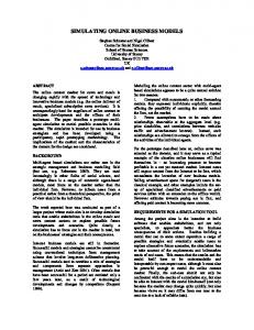
functional requirements that are deemed as very important for modern systems design. MDA defines three models: • A computation independent model (CIM) is a view of a system that does not show details of the structure of systems. It uses a vocabulary that is familiar to the practitioners of the domain in question as it is used for system specification. • A platform independent model (PIM) is a view of a system that on one hand provides a specific technical specification of the system, but on the other hand exhibits a specified degree of platform independence so as to be suitable for use with a number of different platforms. The system is described in platform independent format at the end of the design phase. • A platform specific model (PSM) is a view of a system combining the specifications in the PIM with the details that specify how that system uses a particular type of platform. Model driven engineering relies heavily in model transformation [20]. Model transformation is the process of transforming a model to another model. Thus, different models are created for each development phase and the transition of one phase to another is assisted by automatic model transformation including model to model (M2M), text to model (T2M) and model to text (M2T) transformations leading from requirements to computer programs. The ASEME Platform Independent Model (PIM), which is the output of the design phase, is a statechart that can be instantiated in a number of platforms using existing CASE tools and to an agent platform, the Java Agent Development Framework (JADE). ASEME defines three levels of abstraction for each phase. The first is the societal level. There, the whole multi-agent system functionality is modeled. Then, the agent level zooms in each part of the society, i.e. the agent. Finally, the details that compose each of the agent’s parts are defined in the capability level. In Figure 1, the ASEME phases, the different levels of abstraction and the models related to each one of them are presented. AMOLA provides the syntax and semantics for creating models of multi-agent systems covering the analysis and design phases of the ASEME software development process. It supports a modular agent design approach and introduces the concepts of intra- and inter-agent control. The first defines the agent’s lifecycle by coordinating the different modules that implement his capabilities, while the latter defines the protocols that govern the coordination of the society of the agents. The modeling of the intra and inter-agent control is based on statecharts. The analysis phase builds on the concepts of capability and functionality. AMOLA deals with both the individual and societal aspect of the agents. Then, in order to represent system designs, AMOLA is based on statecharts, a well-known and general language and does not make any assumptions on the ontology, communication model, reasoning process or the mental attitudes (e.g. belief-desire-intentions) of the agents giving this freedom to the designer. The AMOLA models are related to the requirements analysis, analysis and design phases of the software development process. AMOLA aims to model the agent community by defining the protocols that govern agent interactions and each part of the community, the agent, focusing in defining the agent capabilities and the
4
Pavlos Delias and Nikolaos Spanoudakis
functionalities for achieving them. The details that instantiate the agent’s functionalities are beyond the scope of AMOLA that has the assumption that they can be achieved using classical software engineering techniques. In the requirements analysis phase, AMOLA defines the System Actors and Goals (SAG) model, which is similar to the Tropos actor diagram [1], containing the actors and their goals.
Fig. 1. ASEME phases and their AMOLA products.
In the analysis phase AMOLA defines the System Use Cases model (SUC) for decomposing goals to generic activities, the Agent Interaction Protocol model (AIP) for defining the process followed by the participating roles in a protocol in the form of liveness formulas [28], the System Roles Model (SRM) for defining the process of a single role realizing zero or more interaction protocols. In the SRM, We use the Gaia operators ([24], [28]) for creating liveness formulas that define the dynamic aspect of the agent system, what happens and when it happens. Briefly: • • • • • • • •
A.B means that activity B is executed after activity A, ω A means that activity A is executed forever (when it finishes it restarts), A | B means that either activity A or activity B is executed and A || B means activity A is executed in parallel with activity B. A+ means that activity A is executed one or more times, A* means that activity A is executed zero or more times, [A] means that activity A is optionally executed ωn |A | means that activity A is executed forever n times parallel with itself.
In the design phase AMOLA defines the Inter-Agent Control (EAC) model and the Intra-Agent Control (IAC) model, which are based in the language of statecharts [7].
Simulating Multi-agent System Designs Using Business Process Modeling
5
They define the functional and behavioral aspects of the multi-agent system. The model associated to the first level of this phase is the inter-agent control, which defines interaction protocols by defining the necessary roles and the interaction among them. The implementation of the inter-agent control is done at the agent level via the capabilities and their appropriate interaction defined via the intra-agent control. Finally, in the third level each capability is defined with regard to its functionality, what technology is used, how it is parameterized, what data structures and algorithms should be implemented. The intra-agent control model (IAC) defined in this phase corresponds to the Platform Independent Model (PIM) level of MDA. 2.2
Business Process Modeling
Business Process Modeling (BPM) was introduced to allow documented abstractions of the business logic and to bolster model-driven development of operational procedures. Leveraging BPM to guide the software development process appears to provide promising advantages, since it is the business context which ultimately defines the requirements for an information system. In particular, a major advantage of using BPM to design software is that this way business people and software engineers are facilitated in their communication of system requirements, as both types of people can understand a process and model it. Stakeholders are more able to get involved in the system’s design, and hence to assure the alignment of the produced software with the business objectives. Simulation is employed to quantify the impact that a process design is likely to have on its performance, and to numerically indicate the best design alternatives. Regarding business process simulation, various tools exist (see [9], [19] for a discussion on the topic) which facilitate the adoption of BPM as a practical way for designing systems. However, a critical factor in selecting which tool is more appropriate is the modeling language used. Perhaps the most popular modeling languages in designing software systems are the object-oriented ones (e.g. UML), however their lack of process views is criticized [22]. On the other hand, process models do not usually map clearly to a programming environment. Both approaches have their relative advantages, so it is a hard decision to spare one. This is why there have been efforts to bridge object-oriented models and process models through model transformations ([18], [21], [22]). This work contributes to this direction by choosing to define a design model of the agent-based system in BPMN (Business Process Modeling Notation) format [14]. Four major arguments support the selection of BPMN: • • • •
It is expressively rich allowing for virtually any pattern to be modeled, It is quite popular (hundreds of citations appear in the literature), It is standardized and provides a meta-model, and, It smoothly integrates with all phases of software development.
Herein, we briefly present the core elements of BPMN, which are used in our work, in order to facilitate the non-familiar readers. For a more in-depth analysis the reader can refer to [14]. In this work, we used three basic categories of elements:
6
Pavlos Delias and Nikolaos Spanoudakis
Flow objects, connecting objects and swimlanes. Flow objects contain three core elements: 1. Events. Events are illustrated as circles. A thin outline indicates a start event, a double line indicates an intermediate event while a strong outline indicates an end event. When an envelope is enclosed by the circle, this means that the event is triggered by a message. 2. Activities. Activities are represented by rounded rectangles. An activity could be atomic or non-atomic. The non-atomic activities include other activities, which are called Sub-Processes. 3. Gateways. A gateway is represented by a diamond shape and controls divergence and convergence of flow paths. Depending on the symbol specified inside the diamond shape, the gateway defines a forking, merging or joining flow path. Exclusive gateways (XOR) are either blank or contain an ”X” symbol, Inclusive gateways (OR) contain a “O” symbol and parallel gateways (AND) contain a “+” symbol. Connecting objects are the arrows that connect two shapes. When a solid line is used, then that is called sequence flow and it shows a flow or an order in which activities will be performed. In case that the arrow’s line is dashed, the arrow shows the flow of messages between two Participants. The third category (swimlanes) consists of two elements: Pools and Lanes. A Pool represents a Participant in a Process. It is represented with a wide rectangle while a Lane represents sub-part of the Pool and divides it either vertically or horizontally.
3.
Transforming SRM to a BPMN model
For transforming the SRM model to a BPMN model (SRM2BPMN), we need to transform the liveness formula to a valid BPMN graph. We defined the transformation templates shown in Table 1 which are applied recursively to a Gaia formula from left to right. Using these templates an engineer can transform the SRM liveness property to a BPMN model. This transformation is a text to model (T2M) transformation that can be automated using existing techniques (see [23] for a discussion on M2T technologies for ASEME). After this process the software engineer has a ready BPMN model of his agent. The next step is to use this model to simulate the system. If it is a single-agent system it can immediately be used as is for simulation, verification and optimization. Considering a multi-agent system design, however, the individual process models must be combined into a functional eco-system. This fact raises some additional transformation requirements. To begin with, one fundamental necessity is to create the participants who collaborate to realize the process. To achieve this, we create a distinct participant (represented graphically with a Pool in BPMN) for every role instance described in the SRM model. The Pool actually derives from the outer level of the agents’ process
Simulating Multi-agent System Designs Using Business Process Modeling
7
models (the sub-process element is transformed into a swimlane). This transformation brings also an additional action: the elimination of the outermost start and end events. However, in generating the society level, the major actions concern the messages’ flows. First of all, to be more compliant with the business perspective of BPMN, the following rules are applied: Table 1. Templates of extended Gaia operators (Op.) for BPMN model generation Op.
Template
Op.
x|y
x.y
x*
x+
xω
[x]
x || y
|xω|n
Template
• All activities that stand for sending or receiving messages (they are those whose name starts with the “send” or “receive” keywords) are labeled as message type activities. • When a receive activity immediately follows a start event, then the start event and the activity are merged into a start event triggered by a message. • When a receive activity immediately precedes an end event, then the two are merged into an end event triggered by a message. • When a message can be sent to one or more out of many recipients, and this decision has to be evaluated during runtime, then before the “send message” activity a data-based exclusive gateway is added. The last rule was introduced because BPMN does not provide a standard solution for this requirement. This deficiency is discussed in more detail in [3]. A BPMN modeling alternative, which responds to this requirement, is to use signalbroadcasting events. However, the later solution was not adopted since broadcasting does not rigorously match the message exchange logic. Finally, in addition to the above, automated transformational actions, the engineer should manually insert the message flows between the participants, as well as the data variables that they carry. The ASEME extension using the SRM2BPMN transformation is presented in Figure 2. Originally ASEME proposed the transformation of the SRM model to the IAC model, which then allowed the instantiation of the system to an object oriented
8
Pavlos Delias and Nikolaos Spanoudakis
language (using a CASE tool such as Rhapsody3) or the popular JADE4 platform. The SRM2BPMN transformation gives the developers a number of new implementation paths supported with existing tools. The eClarus tool for example, not only allows for simulation but also can export the model to XPDL5 and BPEL6 format.
Fig. 2. ASEME process tree from the analysis phase to implementation.
4.
A Case Study
Throughout this chapter, some parts of the analysis and design models of a real-world agent-based system are presented as we used the transformation presented here-in to validate our system. The requirements were to develop a system that allows a mobile user to access a variety of location-based services supported by a brokering system. The broker has access to a variety of existing web services and an added value services provider agent. For more details about the real-world system, which will be referred to as ASK-IT for the remainder of this document, the reader can refer to [16]. Initially, there were two reasons for simulating the ASK-IT system. The first was that the ASK-IT service providers needed to know if the system can satisfy nonfunctional user requirements, one of which was the delivery of the service within ten 3
IBM Rational Rhapsody is a visual development environment for systems engineers and software developers creating real-time or embedded systems and software. URL: http://www-01.ibm.com/software/awdtools/rhapsody/ 4 The Java Agent Development Environment (JADE) is an open source framework that adheres to the FIPA standards, URL: http://jade.tilab.com 5 The XML Process Definition Language (XPDL) is a format standardized by the Workflow Management Coalition (WfMC) to interchange business process definitions between different workflow products 6 The Business Process Execution Language (BPEL) is an OASIS standard executable language for specifying actions within Business processes with Web Services
Simulating Multi-agent System Designs Using Business Process Modeling
9
seconds. The frequency of service requests was calculated to be one request per 30 seconds. The second was to find out how would the system scale when service demand increased for use in preparing the project’s exploitation plan. 4.1
Generating the Process Models for each Role
In ASK-IT project the Request for Services protocol was specified as shown in Table 2. This protocol is similar to the FIPA Request protocol standard [6]. There are two roles involved, the Service Requester (SR) and the Service Provider (SP). Someone would expect to see the personal assistant and the broker roles implicated, however, the protocol is defined abstractly defining two abstract roles, the SR and SP. The rules for engaging and outcomes are described in free text format. However, the last part is where the process that needs to be followed by the participants is described in a liveness formula. The SR, e.g., first sends the request message and then receives the response message. This protocol is shared by many concrete roles, for example the personal assistant (PA), the broker (BR) and the added-value service provider (AVSP) can use it as service requesters (SR). However, only the BR and the AVSP can use it as service providers (SP). The broker role is a classic broker [12], i.e. the service requester knows how to form a valid request for processing by the service provider but he only interacts with the broker. Thus, the same protocol can be used both for the broker and the service provider. Table 2. Agent Interaction Protocol for the ASK-IT system Request for Services Participants
Service Requester (SR)
Service Provider (SP)
Rules for engaging
He needs to get an e-service within a specific amount of time
He will profit by providing a service within a specific amount of time
Outcomes
He has obtained the e-service results or a denial of service message or a service failure message, or no response
He has provided the e-service results or a denial of service message or a service failure message, or timed out
Process
request for services = send request message. receive response message
request for services = receive request message. process request. send response message
A portion of the SRM for the personal assistant (PA), added-value service provider (AVSP) and broker (BR) roles in ASK-IT is presented in Figure 3. The PA role participates to the request for services protocol as the service requester. The reader should note the interconnection between the role model (SRM) and the agent interaction protocol (AIP) model. For example, the Personal Assistant (PA) role in Figure 3, in the second line, indicates that he participates in the “Request for Services” protocol as a service requester (SR). This implies that the process part (from the AIP model in Table 2) related to an abstract protocol role (e.g. SR) that a concrete role (e.g. PA) assumes must be imported in the liveness model as-is. The
10
Pavlos Delias and Nikolaos Spanoudakis
imported formulas in the liveness formulas of the three concrete roles shown in Figure 3 are written in italics. Applying the transformation templates presented in Table 1 to the formulas presented in Figure 1 we obtain the BPMN models presented in Figures 4, 5 and 6. In Figure 7 all the models have been integrated. Note that each role is on his own swimlane named after his outermost process. Also note, e.g. in the Personal Assistant swinlane, the fact that the “receive response message” atomic process has been combined with the following end event to an end event message. Such events are the points in which the different roles are glued together in the combined process model. Role: Personal Assistant (PA) Protocols: request for services: service requester Liveness: personal assistant = request for services SR request for services SR = send request message. receive response message Role: Broker (BR) Protocols: request for services: service requester, request for services: service provider Liveness: broker = |request for services SPω|10 request for services SP = receive request message. process request. send response message process request = service match. [(invoke data management | request for services SR)] request for services SR = send request message. receive response message Role: Complex Provider (CP) Protocols: request for services: service requester, request for services: service provider Liveness: complex provider = |request for services SPω|10 request for services SP = receive request message. process request. send response message process request = (decide route type. request for services SR. sort routes) | (decide POI types. request for services SR. decide POIs. request for services SR) request for services SR = send request message. receive response message
Fig. 3. A portion of the SRM model for three roles of the ASK-IT project
Fig. 4. The personal assistant agent process model
4.2
Simulating the multi-agent system’s design
The careful reader might have noticed that the final process model has two elements (repeated two times each), which are not justified by the transformation methodology introduced above. These elements are a) the data-based exclusive gateways at the outermost level of the Broker and the Added-Value Service Provider Pools (filled with grey color in the figure) and b) the terminate events that follow these gateways. These elements were added because of the particularities of the simulation tool (eClarus) that we used and which does not allow a straightforward implementation of
Simulating Multi-agent System Designs Using Business Process Modeling
11
the patent |xω|n as described in Table 1. These elements, however, do not alter the model’s logic since the paths which lead to the sub-processes looping were set to be always evaluated as true.
Fig. 5. The broker agent process model added value service provider request for services SP process request decide POI types. request for services SR. decide POIs. request for services SR
decide route type. request for services SR. sort routes request for services SR send receive request response message message
decide route
sort routes
request for services SR send receive request response message message
decide POI types
Decide POIs
request for services SR send receive request response message message
receive request message
Fig. 6. The added-values service provider agent process model
send response message
12
Pavlos Delias and Nikolaos Spanoudakis
Fig. 7. The simulated process model in eClarus tool
Simulating Multi-agent System Designs Using Business Process Modeling
13
In this work, the simulation focus was to test the multi-agent system’s response to the non-functional requirement of delivering the service within 10 seconds (the respective results are presented in Table 3), however the eClarus tool provides more detailed results that concern the resources utilization, waiting times in each activity, costs etc. The presentation of more extended simulation results is out of scope for this paper, however, what is hopefully clear is that an engineer can take advantage of business process simulation tools to evaluate his / her design, without the need to possess expert business process modeling skills or to have the final system implementation ready. Table 3. Simulation results (figures are in milliseconds if not specified otherwise). Process Message arrival every Instances Started Instance Completed Normal Completed Terminated With Unhandled Error Average Cycle Time Maximum Cycle Time
5.
RequestForServices_ServerSide 30 sec 15 sec 1000 1000 996 992 996 992 0 0 0 0 5,287.47 sec 5,169.83 sec 8,392.49 sec 12,576.34 sec
5 sec 1000 989 989 0 0 6,669.69 sec 14,713.14 sec
Related Work and Conclusion
In this paper the BPMN (Business Process Modeling Notation) was selected to provide multi-agent systems’ engineers with an extra functionality for producing a high quality design. BPMN was selected because it is an intuitive graphical process language, and because it is supported by a plethora of tools (http://www.bpmn.org/BPMN_Supporters.htm reports over 70 existing tools). BPMN appears to be a critical component in model-driven business transformation ([5], [8], [10], [13]), however existing works seem to focus on the transformation of BPMN diagrams to other models, while in this paper the focus was on the inverse direction. In [13], the authors propose a Visual Service Design Tool as a BPMN editor which includes a transformation to BPEL module. The same functionality is offered by [4] and eClarus. The later, promises indeed a round-trip transformation between BPMN and BPEL. In [10] BPMN diagrams are transformed into YAWL Nets [26], a process language which extends Petri-Nets. Petri-Nets are also the target language in which BPMN diagrams are transformed in [5]. In that work, authors propose an initial transformation from BPMN to a normalized form aiming at its use by software agents. In the same paper, the opposite transformation (agents to BPMN) is characterized as “an interesting research task” and as a factor that it would “increase the understanding of existing (multi-agent) systems significantly”, a discussion which outlines the contribution of our work. With respect to our knowledge, this is the first attempt of a model-driven transformation of this direction (agents model to BPMN).
14
Pavlos Delias and Nikolaos Spanoudakis
The final product of our SRM2BPMN transformation is a process model which is available for simulation (or even transformation to other formats). The simulation allows the modeler to enter the verification and optimization phases, and thus to: • Determine if the system meets its requirements • Determine how the system would scale • Identify errors in system conception and propose strategies for resolving them either through a next development iteration (including risks calculation and different technology use) or by directly returning to the phase that introduced the error and restarting from there (useful in agile development) • Optimize the system regarding resource allocation and utilization All these issues are rarely tackled by existing AOSE methodologies. Our future work is about developing the transformation tool and inserting it to the ASEME tool repository. Moreover, we plan to expand the transformation scope allowing the transformation of an IAC model to BPMN and vice-versa. This way the developer will be able to use a BPMN model for simulating his system and then implementing it using the JADE popular agent platform without having to insert information already existing in the source model (like e.g. inter-agent messages exchange between two agent roles).
References 1. Bresciani, P., Giorgini, P., Giunchiglia, F., Mylopoulos, J., and Perini, A.: TROPOS: An Agent-Oriented Software Development Methodology. Journal of Autonomous Agents and Multi-Agent Systems, 8, (3), 203-236 (2004) 2. Beydeda, S., Book, M., Gruhn, V.: Model-Driven Software Development. Springer (2005) 3. Decker, G., Puhlmann, F.: . Extending BPMN for modeling complex choreographies. In Proceedings of the COOPIS 2007, Vilamoura, Portugal, 24-40 (2007) 4. Doux, G., Jouault, F. and Bézivin, J.: Transforming BPMN process models to BPEL process definitions with ATL. In GraBaTs 2009: 5th International Workshop on Graph-Based Tools, Zurich,(2009) 5. Endert, H., Hirsch, B., Küster, T., Albayrak, S.: Towards a Mapping from BPMN to Agents. Service-Oriented Computing: Agents, Semantics, and Engineering, Springer Berlin, Heidelberg. Lecture Notes in Computer Science vol. 4504, pp. 92-106 (2007) 6. FIPA TC Communication, FIPA Request Interaction Protocol Specification, Document number SC00026H, Foundation for Intelligent Physical Agents, December 2002. URL: http://www.fipa.org/specs/fipa00026/ 7. Harel D., Kugler, H.: The RHAPSODY Semantics of Statecharts (Or on the Executable Core of the UML). In LNCS vol. 3147, Springer-Verlag, Berlin Heidelberg, 325-354. (2004) 8. Hauser, R.: Automatic transformation from graphical process models to executable code. Eidgenössische Technische Hochschule Zürich (2010) 9. Jansen-Vullers M., Netjes, M.: Business Process Simulation – A Tool Survey. In Workshop and Tutorial on Practical Use of Coloured Petri Nets and the CPN Tools, Aarhus, Denmark, October 2006 10.Jianhong Y., Song W.: Transformation of BPMN Diagrams to YAWL Nets, Journal of Software, Vol 5, No 4, pp. 396-404 (2010)
Simulating Multi-agent System Designs Using Business Process Modeling
15
11.Kleppe, A.G., Warmer, J., Bast, W.: MDA Explained: The Model Driven Architecture: Practice and Promise. Addison-Wesley, Boston, MA, USA (2003) 12.Klucsh M., Sycara K.: Brokering and Matchmaking for Coordination of Agent Societies: A Survey. In Omicini et al. (editor), Coordination of Internet Agents, Springer (2001) 13.Küster, T., Heßler A.: Towards Transformations from BPMN to Heterogeneous Systems. Business Process Management Workshops. D. Ardagna, M. Mecella and J. Yang (eds.), Springer Berlin Heidelberg. Lecture Notes in Business Information Processing vol. 17, pp. 200-211 (2009) 14.Object Management Group: Business Process Modeling Notation (BPMN) (2009) 15.Object Management Group: Unified Modeling Language, Superstructure, V2.1.2. (2007) 16.Moraitis, P., Spanoudakis, N.I.: Argumentation-based agent interaction in an ambientintelligence context. IEEE Intelligent Systems 22(6), 84–93 (2007) 17.Rana, O. F., Stout, K.: What is scalability in multi-agent systems?. In Proceedings of the Fourth international Conference on Autonomous Agents (Barcelona, Spain, June 03 - 07, 2000). AGENTS '00. ACM, New York, NY, 56-63 (2000) 18.Redding, G., Dumas, M., Hofstede, A., H.M. ter, Iordachescu, A.: Generating Business Process Models from Object Behavior Models, Information Systems Management, 25(4), 319-331 (2008) 19.Rozinat, M.T. Wynn, W.M.P. van der Aalst, A.H.M. ter Hofstede, C.J. Fidge, Workflow simulation for operational decision support, Data & Knowledge Engineering, Volume 68, Issue 9, pp. 834-850 (2009) 20.Sendall, S., Kozaczynski, W.: Model transformation: The heart and soul of model-driven software development. IEEE Software 20(5), 42–45 (2003) 21.Shan, Z., Long, Z., Luo, Y. ,Peng, Z.: "Object-Oriented Realization of Workflow Views for Web Services – An Object Deputy Model Based Approach," in Advances inWeb-Age Information Management, 468-477 (2004) 22.Snoeck, M., Poelmans, S., Dedene, G.: An Architecture for Bridging OO and Business Process Modeling, In: Proc. Technology of Object-Oriented Languages and Systems (TOOLS 33), pp.132 (2000) 23.Spanoudakis N., Moraitis P.: Model-Driven Agents Development with ASEME. In: 11th Int. Workshop on Agent Oriented Software Engineering (AOSE 2010), Toronto, Canada (2010) 24.Spanoudakis, N.: The Agent Systems Engineering Methodology (ASEME). Ph.D. thesis, Paris Descartes University (2009) 25.Spanoudakis, N.I., Moraitis, P.: The agent modeling language (AMOLA). In: Dochev, D., Pistore, M., Traverso, P. (eds.) AIMSA. Lecture Notes in Computer Science, vol. 5253, pp. 32–44. Springer (2008) 26.van der Aalst, W. M. P., ter Hofstede, A. H. M.: YAWL: yet another workflow language, Information Systems, Volume 30(4), 245-275 (2005) 27.Yamamoto, G. and Nakamura, Y.: Architecture and performance evaluation of a massive multi-agent system. In Proceedings of the Third Annual Conference on Autonomous Agents (Seattle, Washington, United States). O. Etzioni, J. P. Müller, and J. M. Bradshaw, Eds. AGENTS '99. ACM, New York, NY, 319-325 (1999) 28.Zambonelli, F., Jennings, N.R., Wooldridge, M.: Developing multiagent systems: The gaia methodology. ACM Trans. Softw. Eng. Methodol. 12(3), 317–370 (2003)