10, D-64289 Darmstadt, Germany .... of robots (wheeled, legged, tracked robots, submarines, helicopters) and sensors.
Preprint of a paper which appeared in the Proceedings of the 2008 International Conference on Simulation, Modelling and Programming for Autonomous Robots (SIMPAR) Venice, Italy, Nov. 03 - 07 2008
Simulation of Multi-Robot Teams with Flexible Level of Detail Martin Friedmann, Karen Petersen, and Oskar von Stryk Technische Universit¨ at Darmstadt, Department of Computer Science Hochschulstr. 10, D-64289 Darmstadt, Germany { friedmann, petersen, stryk }@sim.tu-darmstadt.de, WWW home page: http://www.sim.tu-darmstadt.de
Abstract. A key methodology for the development of autonomous robots is testing using simulated robot motion and sensing systems. An important issue when simulating teams of heterogeneous autonomous robots is performance versus accuracy. In this paper the multi-robot-simulation framework (MuRoSimF) is presented which allows the flexible and transparent exchange and combination of the algorithms used for the simulation of motion and sensing systems of each individual robot in a scenario with individual level of realism. It has already been used successfully for the simulation of several types of legged and wheeled robots equipped with cameras and laser scanners. In this paper the core functionalities of MuRoSimF are presented. Existing algorithms for simulation of the robots’ motions are revised. Newly added features including the execution of the simulation on multi core CPUs and two different algorithms for the simulation of laser scanners are presented. The performance of these features is tested in an urban scenario using wheeled robots.
1
Introduction
The development of control software for teams of autonomous robots is a highly challenging task. Reasons for lack of performance as well as for failure are extremely difficult to analyze by experimental evaluation only, because an autonomous robot usually consists of a highly interacting set of different software and hardware modules. Therefore one of the most valuable tools supporting the development of control software is software in the loop (SIL) testing using simulation of robot hardware under real-time conditions. The benefits of simulation are manifold, including testing of software under repeatable and controllable conditions and unlimited availability (compared to real hardware). The general requirements on the simulation may differ significantly depending on the scope of the simulation experiment. For example, a high level of detail in robot motion simulation using multi-body dynamics is important for investigation of motion control of robots with high motion dynamics and inertial stabilization like humanoid or flying robots. On the other hand for four-wheeled robots on even ground usually vehicle kinematics models are sufficient to test team cooperation and kinetical models which would need a larger computational
effort are not required. In some cases, even a too realistic robot motion simulation may not be desireable for some tests. E.g., the disturbing effects of a robot’s motion like sliding or shaking may overshadow other sources of observed errors. Similar considerations apply to the simulation of sensors: For testing sensor data processing, it is necessary to have a high fidelity simulation of the sensors, including simulation of possible sources of errors. If higher levels of abstraction within the control software (like behavior control) are under consideration, it may be useful to provide the software with ground truth data from the simulation skipping sensor simulation and processing completely. The latter kind of tests are very difficult to conduct on real robots, as ground truth data usually require additional sensors in the environment and may also suffer from measurement errors. An obvious tradeoff when creating a robot simulation is fidelity vs. realtime performance. 1.1
Requirements for Robot Simulation
As mentioned before, the requirements on the simulation of mobile autonomous robots may differ strongly for different purposes even for the same robot. One way to handle this problem is to use different simulators on different levels of detail and realism. Although often practiced, this approach has the major drawback of multiplying user efforts as well as sources of errors, as each robot has to be modeled for each simulator and each simulator has to be linked to the robot control software for specific tests. Therefore it is highly desirable to use one simulator enabling different levels of accuracy and realism in robot motion and sensing (sub-)systems. Depending on the requirements, different simulation algorithms for each robot of a team within one scenario should be selectable at the same time, e. g., by having a full multi-body system dynamics simulation for one robot and kinematic models for other robots. To achieve this flexibility for the simulation setup, the simulator must provide means to exchange a variety of algorithms with different level of physical detail for the same robot motion or sensor (sub-)system as well as the possibility to flexibly combine these algorithms for different robots in the scene. A second issue for simulation of large robot teams is real-time-performance: When executing simulations on normal laptop or desktop computers (as in many cases of research and education), CPU power often is a limiting factor for the overall performance of a simulation. As the majority of all new laptop and desktop computers features at least a dual-core CPU, optimal performance of a simulation requires support for multi-threaded execution. 1.2
Existing Robot Simulators
USARSim [1] is an open source simulation which supports several different types of robots (wheeled, legged, tracked robots, submarines, helicopters) and sensors (cameras, different distance sensors, RFID sensors, odometry, sound, motion sensors, etc.). Physics simulation and visualization are based on the game engine Unreal Engine by Epic Games [2].
Several simulators rely on the Open Dynamics Engine ODE [3] for physics simulation: Gazebo [4] is the 3D simulator of the player/stage project [5] providing different sensors (cameras, distance sensors, GPS) and several types of robots (wheeled, legged robots, helicopters). SimRobot [6] is a simulator which supports wheeled and legged robots which can be equipped with some sensors, e.g. cameras, distance sensors, and bumpers. Webots [7] is a commercially available simulator that is able to simulate many different types of robots, including wheeled, legged and flying robots. It comes up with many configurable sensors, e.g. cameras, distance sensors, range finders, touch sensors, light sensors, GPS. Microsoft Robotics Studio [8] is another commercially available simulator. It also supports many different robots and sensors. Physics simulation is done with PhysX by NVIDIA [9], which can be accelerated by using special hardware. Simbad [10] is an open source simulator written in Java. It supports some different robot models and sensors like cameras, range sensors and bumpers. Dynamics are calculated with a simplified physics engine. To the authors’ knowledge none of these 3D simulators fulfills all requirements stated before. Most of them depend on external physics engines, restricting them to a very specific level of accuracy of the algorithms used for simulation of robot motion dynamics and for the numerical integration of the underlying initial value problems for ordinary differential equations. If no algorithms on different levels of accuracy are available, these effects only can be reached by huge efforts like remodeling parts of the scene on different levels of detail. Also multi-threading is not available in most of the aforementioned simulations. The Unreal Engine 3 supports the usage of multiple CPUs, but USARSim is currently based on the Unreal Engine 2 without multi-threading. PhysX, which is used by the Unreal Engine 3 and by Microsoft Robotics Studio, supports multi-threading, but it is not stated if Microsoft Robotics Studio makes use of this functionality. ODE, which is used by Gazebo, Webots and SimRobot is not multi-threaded. In this paper the Multi-Robot-Simulation-Framework (MuRoSimF) is presented. It provides a wide variety of simulation algorithms which can be combined to create simulations for autonomous mobile robots on different levels of accuracy. As the data models describing the robot’s structure and state are separated from the algorithms used, algorithms can be exchanged transparently. MuRoSimF has already been used successfully for the simulation of several mobile autonomous robots (e. g. [11, 12]). Recent developments covered in this paper include algorithms for the simulation of laser scanners and the possibility to execute simulations multi-threaded thus improving scalability on multi-core CPUs.
2 2.1
Structure of Simulation in MuRoSimF Data Models
The basic building blocks for the data models of robots and environment are so called objects. An object is a container for a set of properties which can be constant or variable. Properties can be assigned at runtime to each object.
It is possible to declare a set of properties of different objects to be explicitly equal, so that all properties will share the same space in memory thus avoiding unnecessary copying of data. Due to this feature objects representing sensors can be attached easily to any other object by simply sharing the properties of interest, e. g. the object’s position and orientation. Complex models can be created by joining any number of objects into a so called compound. Compounds may have arbitrary internal structures and relations of the single objects. Robots are special compounds with a tree shaped structure. The basic building blocks for a robot’s kinematic structure are the robot’s base, forks, fixed translations and rotations (to represent rigid bodies) as well as variable rotations and translations (to represent joints). For the sake of simplicity only binary forks are used. During model setup the kinematic structure of a robot is created from these basic blocks. To create a robot model a set of helper functions is provided. These functions allow creation of the tree in a depth-first manner as well as adding constant properties to each part of the tree. Currently models are programmed directly in C++. Readers to load models created with external 3D modeling tools can be added to MuRoSimF. As the rendering of shapes is based on textured meshes, this will also improve the quality of the simulation’s visualization. 2.2
Algorithms
To make the simulation do something, simulation algorithms are needed. Algorithms are classes which can be connected during simulation setup to the data models of a simulation. When an algorithm is connected to an object, the algorithm can add additional variable properties dynamically to the object. Due to this feature, objects only store variable properties required or calculated by the algorithms in use. Externally implemented simulation algorithms can be used within MuRoSimF based simulations by creating a new algorithm class which will connect to the required properties of the model. This approach is less efficient than implementing algorithms using the tools provided by MuRoSimF as all required properties need to be copied between the external algorithm and the rest of the simulation. 2.3
Controllers
Controllers are special algorithms which may change and read variable properties of an object due to external requests. They are used to interface the simulation to external control software, thus enabling software in the loop testing. Controllers can interface to data stream oriented connections like serial ports or TCP-sockets. As controllers may connect to any property of a simulated robot, new controllers for arbitrary external control software can be added to MuRoSimF. Several generic controllers for setting joint values and reading sensors are provided. For more complex control tasks a controller is provided which can execute arbitrary control algorithms loadable from a dynamic link library.
2.4
Execution of Simulations
After setup of the models and algorithms of a simulation, the simulation can be executed. To do this, all algorithms are registered at a scheduler which will execute each algorithm at an arbitrary rate, thus allowing algorithms with different purposes to be run at different speeds (e. g. high rates for robot dynamics and lower rates for camera simulation). The execution rate can be chosen individually for each algorithm and each robot, enabling fine tuning of the performance and accuracy of the simulation. As the structures required for the exchange of data between the algorithms in use are created during simulation setup, it is not possible to exchange algorithms at runtime. The set of algorithms registered at the scheduler can be structured in two ways. Sequences of algorithms which have to be executed always in the same order and at the same rate can be added as one item to the scheduler. It is possible to execute a set of such sequences in parallel threats. Parallel execution can be controlled in several ways: It is possible to spawn an individual threat for each sequence, thus exploiting the maximum number of cores on a CPU present, but it is also possible to limit the number of parallel threads, e. g. if part of the CPU time has to be saved for other purposes.
3
Motion Simulation
MuRoSimF provides several modules for robot motion simulation, differing in levels of accuracy, complexity and generality. The modules can be divided into two major groups: robot-specific algorithms and general algorithms. 3.1
Robot Specific Algorithms
Two robot specific algorithms are currently provided for kinematic motion simulation for biped robots and for vehicles with differential drive. Both algorithms make strong assumptions limiting the motion possibilities as well as the accuracy of the simulation. Nevertheless these algorithms have been used successfully when investigating the high level behavior for homogeneous (e. g. [13]) and heterogeneous (e. g. [12]) teams of robots. Another merit of these algorithms is the low complexity. It is possible to simulate many robots in real time on a standard computer. Kinematic biped simulation. The kinematic simulation for biped robots is based on the assumption, that the robot places its feet on a plane and that always at least one foot touches this plane. Using this assumption the robot’s motion is simulated by calculating the direct kinematics of the robot while keeping one foot fixed to the ground. Whenever a contradiction occurs (e.g. one foot penetrating the ground plane), the standing foot is swapped. A feature of this algorithm is the fact, that the simulated humanoid robot does not suffer from effects like shaking, sliding or falling over which is helpful for certain SIL tests.
Differential Drive. Motion of vehicles with differential drive is simulated under similar assumptions: Both wheels always touch the ground plane. In this case the angular and linear velocity of the vehicle’s base can be calculated from the velocity of the wheels. 3.2
General Algorithms
The algorithms presented in this section do not make any assumptions on the robot’s structure. Point model. The point model is the most simple motion simulation algorithm available in MuRoSimF. Only motion of the robot’s base is considered (and controlled) externally. If necessary (e. g. when investigating control of articulated external sensors), direct kinematics relative to the robot’s base can be calculated to give the position and orientation of the robot’s parts. This algorithm can be used when investigating large scale scenarios considering problems like team communication or coordination. Simplified dynamics simulation. The simplified dynamics simulation makes no assumption on the robot’s kinematic structure. Unlike the algorithms presented before, the following algorithm considers the dynamics of a robot system. To allow for real-time simulation of teams of robots, this algorithm simplifies the simulated robot to a single body with center of gravity (CoG) and inertia tensor changing due to the motion of the robots joints. All internal motions of the robot are calculated by direct kinematics. Motions of the robot relative to the environment are calculated by summing up any external forces and torques (e. g. caused by friction, collision or gravity) at the current CoG and calculating the resulting linear and angular accelerations of the CoG. The algorithm does not consider the forces generated by the servo motors of the robot’s joints. Instead it assumes that the motors are moving at a given rate or acceleration. Further the algorithm neglects any effects caused by relative motions of the parts of the robot like Coriolis forces. Even though these simplifications limit the use of this algorithm when studying whole body motions of a robot, the algorithm has been used successfully for several types of wheeled, biped and quadruped robots. As the algorithm requires the external forces experienced by the robot, detecting and handling of collisions are essential. Detection of collisions is currently based on primitive shapes (box, sphere, cylinder, plane) assigned to the bodies of the robots. To avoid intersecting each body of each robot with each other body in the scene, a hierarchy of bounding volumes is used (see [11]). As collisiondetection and -handling are modules separated from the motion simulation, they can be substituted by other algorithms, e. g. by collision detection using meshes. 3.3
Discussion
The algorithms presented in this section differ in complexity, realism and generality. Depending on the requirements of a given simulation setting an appropriate algorithm can be chosen allowing to set up an adequate simulation.
Due to the modular design of MuRoSimF any other algorithm like full multibody system dynamics simulation can be added easily and be exchanged transparently for existing models.
4
Sensor Simulation
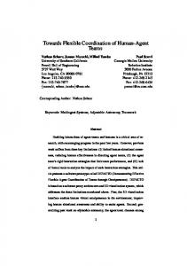
Simulation of sensors is performed by algorithms which are connected to the respective object representing the sensor under consideration. These algorithms may need further information to simulate the sensor (e. g. rendering information for the scene in case of camera simulation). In the following subsections the capabilities of MuRoSimF for simulation of internal sensors and cameras already presented in [11, 13] are revised. After this the newly developed algorithms for simulation of laser scanners are discussed in detail. Internal sensors. Simulation of internal sensors like joint encoders, gyroscopes or acceleration sensors is based on respective physical values calculated by the simulation. Sensor errors like noise, saturation or limited resolution of AD converters can be simulated in a post processing step. Camera. The camera simulation uses the OpenGL based visualization module of MuRoSimF which is also used for generating the main view. The scene is rendered from the camera’s point of view, later it is possible to apply blur using a Gaussian filter or distortion like it is caused by a lens. Laser scanner. MuRoSimF provides two different approaches for simulating distance sensors like laser scanners. One approach is using the z-Buffer information generated during OpenGL based 3D rendering. The other approach is calculating intersections of rays with the objects present in the simulation. The approaches vary in terms of performance and usability, depending on the configuration of the laser scanner (2D/3D, resolution) and the structure of the scene (number of static and dynamic objects and their distance to the sensor). Using the z-buffer to simulate a laser scanner is similar to the camera simulation up to the point, that the complete scene is rendered from the point of view of the laser scanner. As only the depth-information is processed, it suffices to render the geometry data of all objects omitting lighting, color or texture information thus improving performance. The depth-information is read back after rendering and can be used to calculate the orthogonal distance of the depicted objects from the viewing plane. Considering the direction of the rays, this information can be used to calculate the length of the rays (see Fig. 1). Within the standard pinhole model used by OpenGL rendering the view rays are distributed uniformly on the projection plane yielding a non-uniform angular distribution of the rays (cf. Fig. 1). For a scan of 2n + 1 rays of the range [−αmax . . . αmax ], the i-th ray from the center has the direction � � i · tan(αmax ) . α ˜ i = arctan n
Fig. 1. Left: Distribution of the rays and measured distance in z-buffer. Middle: Vehicle with 3D laser scanner, augmented with visualization of the scan. Right: Depth-image read from the z-Buffer.
As most real laser scanners have a uniform angular distribution, a mapping of the distances calculated from the z-buffer to the rays of the simulated scanner must be performed. This can be done by using interpolation, optionally preceded by supersampling (that is, rendering at a higher resolution than desired). As the pinhole projection is limited to aperture angles below 180 deg, the opening angle for the simulated laser scanner is limited. Due to the non-uniform distribution of the angles it should be well below this limit. Simulation of laser scanners with a wider angular range can be done using multiple rendering passes with different viewing directions. Simulating a laser scanner by calculating ray intersections may use an arbitrary number of rays with any distribution. To speed up the calculation, a hierarchy of bounding volumes is used. The same hierarchy already is used for collision detection (see [13]), so it imposes no extra overhead on the simulation. The calculation is further sped up exploiting local coherence: If a ray intersects an object, it is likely, that a neighboring ray will also intersect this object, so that the search space can be limited further. To integrate simulated laser scanners with a control application a controlleralgorithm (see Sect. 2.3) can be attached to the simulated laser scanner. This controller is used to handle communication with any external application. A special controller has been developed implementing the SCIP2.0 (see [14]) protocol of the widely used Hokuyo URG04LX laser scanner. Using this controller, applications can be connected transparently to the real or the simulated device.
5 5.1
Results Applications
MuRoSimF has been used to create several simulations for a wide range of robots differing in mode of locomotion as well as simulated sensors. Due to the easy recombination of the existing algorithms simulations adequate for a given purpose, e. g. by choosing appropriate algorithms for motion or sensor simulation can be created easily. Simulation of biped robots has been used successfully for testing several modules of the control software including image processing, world modeling, behavior
Fig. 2. Left: Simulation of a team of humanoid soccer playing robots. Middle: Simulation of a newly developed quadruped robot. Right: Simulation of a heterogeneous team of autonomous robots.
control and motion generation. Beyond biped robots MuRoSimF-based simulations have been used for several purposes including development of a quadruped robot and research in the field of cooperation for heterogeneous teams of autonomous robots (see, e.g., Fig. 2 and [12, 15]). Most recently a simulation for a newly developed small four-wheeled autonomous offroad vehicle equipped with a laser scanner has been created. This simulation is used to evaluate high level behavior and sensor processing for control applications for single vehicles as well as teams of vehicles (cf. Figs. 3, 4). The simulation consists of model data for the environment and for each simulated vehicle. Each vehicle is modeled as a compound object, including a laser scanner object. Motion simulation is based on the simplified dynamics algorithm presented in Sect. 3.2. The laser scanner can be simulated with either algorithm described in Sect. 4.
Fig. 3. Structure of the simulation: Vehicle data, motion and laser scanner (LS) simulation and the controllers can be duplicated to simulate more than one vehicle. Arrows indicate direction of data flow.
5.2
Performance of Simulation
The performance of the simulation has been measured for the simulation of fourwheeled vehicles in a simplified urban scenario described above. Measurements
Fig. 4. Simulation of the vehicle (left) connected to a RoboFrame-based control application (right). The visualization of the simulation is augmented with the readings from the vehicle’s laser scanner.
were taken on two laptop computers (cf. Table 1) equipped with a single resp. dual core CPU. The performance of the motion simulation was measured with disabled laser scanners. Only the collision detection and the dynamics modules (both running at 1000 fps) and the controllers were active in this test. Using one core of the CPU of computer A up to 20 vehicles could be simulated in real time. Using both cores (parallelizing only dynamics simulation, but not collision detection), up to 30 vehicles could be measured. On computer B (single core CPU) up to 19 vehicles could be simulated in real time. The performance of the laser scanner simulation has been measured for several setups of laser scanners in 2D and 3D configurations (see Table 2). During these measurements the motion simulation was running single threaded at 1000 fps. An interesting result of the measurements is the fact, that simulation of scanners with many rays is more efficient using the z-buffer method while calculation of ray intersections is more efficient for scanners with very view rays. Another result from these measurements is, that the performance of the single simulation algorithms strongly differs by the hardware used. On computer A the break even in performance of the two laser-scanner-simulation algorithms was at Table 1. Computers used for performance measurements
Computer A Computer B Intel Centrino Duo Intel Pentium M (dual core) (single core) Speed 1.67 GHz 1.86 GHz RAM 1 GByte 1 GByte Graphics-chipset Intel 945GM express ATI Mobility Radeon X700 CPU
Table 2. Measurement of real-time performance of laser scanner simulation
Method z-buffer
Resolution 10 × 1 100 × 1 100 × 10 100 × 100 ray-intersection 10 × 1 100 × 1 100 × 10
Scanner Vehicles on FPS Computer A Computer B 10 7 12 10 7 10 10 5 6 10 2 5 10 9 16 10 5 10 10 2 2
much less rays then on computer B. Using the modular approach of MuRoSimF it is possible to choose an algorithm appropriate for the respective computer.
6
Conclusions and Outlook
In this paper MuRoSimF, a framework capable of creating 3D simulations for teams of autonomous mobile robots with different modes of locomotion (wheeled, biped, quadruped) and different sensors has been presented. To the authors’ best knowledge it has the unique feature of enabling a very flexible selection of simulation methods and algorithms for motion and sensing (sub-)systems with different levels of realism for different robots in the same scene. Specifically, a newly developed simulation for teams of wheeled vehicles has been presented and evaluated in this paper. Several improvements of the earlier developments described in [11, 13] have been achieved: The high performance of MuRoSimF when simulating legged robots could be transfered to wheeled robots. Two new algorithms for the simulation of laser scanners were added to the framework. They can be exchanged transparently allowing to choose the algorithm appropriate for a given simulation task. It is planned to enhance these algorithms by considering distortions of the scan caused by the robot’s motion. First steps were taken to enable the distribution of the simulation to multiple CPUs. Even though currently only the algorithms used for motion simulation can be parallelized, by using a dual core CPU the number of vehicles simulated in real-time could be increased by 50%. The next step in improving the simulation’s performance will be the development and integration of collision-detection algorithms which can be executed in parallel threads. To provide more realistic simulations, it is planned to validate motion- and sensor-simulation algorithms by comparing performace of simulated and real devices and improving model data. One possible way to do this is the iterative approach presented in [16] to determine the motor data of a robot motion dynamics model. Even though MuRoSimF is not open source, the source code is available upon request for research and educational purposes (see www.dribblers.de/murosimf).
Acknowledgment. Parts of this research have been supported by the German Research Foundation (DFG) within the Research Training Group 1362 “Cooperative, adaptive and responsive monitoring in mixed mode environments”.
References 1. S. Carpin, M. Lewis, J. Wang, S. Balakirsky, and C. Scrapper. USARSim: a robot simulator for research and education. In Proc. of the 2007 IEEE Intl. Conf. on Robotics and Automation (ICRA), 2007. 2. Epic Games, Unreal engine, www.epicgames.com. 2007. 3. R. Smith. ODE - Open Dynamics Engine, www.ode.org. 2007. 4. N. Koenig and A. Howard. Gazebo - 3D multiple robot simulator with dynamics, website http://playerstage.sourceforge.net/gazebo/gazebo.html. 2003. 5. B. P. Gerkey, R. T. Vaughan, and A. Howard. The Player/Stage project: Tools for multi-robot and distributed sensor systems. In Intl. Conf. on Advanced Robotics (ICAR), pages 317 – 323, Coimbra, Portugal, 30 June - 3 July 2003. 6. T. Laue, K. Spiess, and T. R¨ ofer. SimRobot - a general physical robot simulator and its application in RoboCup. In A. Bredenfeld et al., editor, RoboCup 2005: Robot Soccer World Cup IX, number 4020 in Lecture Notes in AI, pages 173–183. Springer, 2005. 7. O. Michel. Cyberbotics ltd. - webots(tm): Professional mobile robot simulation. Intl. Journal of Advanced Robotic Systems, 1(1):39–42, 2004. 8. Microsoft Robotics Studio, msdn.microsoft.com/robotics/, 2007. 9. AGEIA PhysX website, http://www.ageia.com/physx/. 2007. 10. L. Hugues and N. Bredeche. Simbad: an autonomous robot simulation package for education and research. In Proceedings of The Ninth International Conference on the Simulation of Adaptive Behavior (SAB’06), Rome, Italy, 2006. 11. M. Friedmann, K. Petersen, and O. von Stryk. Tailored real-time simulation for teams of humanoid robots. In U. Visser, F. Ribeiro, T. Ohashi, and F. Dellaert, editors, RoboCup 2007: Robot Soccer World Cup XI, volume 5001 of Lecture Notes in CS/AI, pages 425–432, Berlin/Heidelberg, 2008. Springer-Verlag. 12. J. Kiener and O. von Stryk. Cooperation of heterogeneous, autonomous robots: A case study of humanoid and wheeled robots. In Proc. IEEE/RSJ International Conference on Intelligent Robots and Systems (IROS), pages 959–964, San Diego, CA, USA, Oct. 29 - Nov. 2 2007. 13. M. Friedmann, K. Petersen, and O. von Stryk. Adequate motion simulation and collision detection for soccer playing humanoid robots. In Proc. 2nd Workshop on Humanoid Soccer Robots at the 2007 IEEE-RAS Int. Conf. on Humanoid Robots, Pittsburgh, PA, USA, Nov. 29 - Dec. 1 2007. 14. H. Kawata, A. Ohya, and S. Yuta. Development of ultra-small lightweight optical range sensor system. In Proc. IEEE/RSJ International Conference on Intelligent Robots and Systems (IROS), 2005. 15. M. Friedmann, S. Petters, M. Risler, H. Sakamoto, D. Thomas, and O. von Stryk. A new, open and modular platform for research in autonomous four-legged robots. In K. Berns and T. Luksch, editors, Autonome Mobile Systeme 2007, Informatik aktuell, pages 254 – 260, Kaiserslautern, 18 - 19 Oct. 2007. Springer Verlag. 16. M. Stelzer, M. Hardt, and O. von Stryk. Efficient dynamic modeling, numerical optimal control and experimental results for various gaits of a quadruped robot. In CLAWAR 2003: 6th International Conference on Climbing and Walking Robots, Catania, Italy, pages 601–608, Sept. 17-19 2003.