580
IEEE TRANSACTIONS ON EDUCATION, VOL. 53, NO. 4, NOVEMBER 2010
Simulation Tools for Power Electronics Courses Based on Java Technologies Carlos A. Canesin, Senior Member, IEEE, Flávio A. S. Gonçalves, and Leonardo P. Sampaio
Abstract—This paper presents interactive power electronics educational tools. These interactive tools make use of the benefits of Java language to provide a dynamic and interactive approach to simulating steady-state ideal rectifiers (uncontrolled and controlled; single-phase and three-phase). Additionally, this paper discusses the development and use of Java applet programs to assist the teaching of conventional power electronics rectifier circuits and to serve as a first design tool for basic laboratory experiments in power electronics courses. Comparison was made among results obtained using a well-known simulator package, experimental results, and the developed interactive simulation applets in order to validate the latter. Index Terms—Circuit simulation, education, power electronics, student experiments, thyristors.
I. INTRODUCTION DUCATION is one of the most important foundations for supporting social development in a country. In the last decades, researchers have been refining concepts/techniques and developing new tools to support the improvement of educational processes [1]. The traditional form of teaching in the classroom can be complemented by the use of interactive systems based on computers. These systems can provide a high-quality learning environment that improves student learning and, consequently, the educator’s productivity [2]. The evolution of computers associated with the rapid emergence of the World Wide Web (WWW) and its associated tools has provided educators with a powerful and effective mechanism for information delivery. This environment can easily incorporate the latest hypermedia technologies (hypertexts, interactive simulations, videos/sounds, databases, remote-controlled instruments) to create and to manage educational courses, virtual laboratories, and virtual classrooms [3], [4]. The main advantages of educational systems based on the WWW are that they are independent of time and location, have a simple and familiar Web browser-based interface, and offer the possibility of simultaneous attendance [3]–[5]. Until few years ago, the teaching of power electronics circuits was based on methodologies in which concepts were presented in a static fashion. To illustrate these concepts dynami-
E
Manuscript received September 23, 2008; revised October 21, 2009. First published November 24, 2009; current version published November 03, 2010. This work was supported by CNPq (National Council of Technological and Scientific Development). The authors are with UNESP-FEIS, Department of Electrical Engineering, São Paulo State University, 15385-000 Ilha Solteira, SP, Brazil (e-mail:
[email protected];
[email protected];
[email protected]). Digital Object Identifier 10.1109/TE.2009.2036157
cally and interactively is usually difficult in a traditional classroom using conventional explanations and static tools. Therefore, these methodologies have been supplemented with computer simulations and object-oriented graphic tools. The learning or teaching of a technical engineering subject, such as power electronics, is often complicated because the system can react in many different ways to parameter changes. This type of system dynamic behavior can, in many cases, be easily explained if these dynamic changes can be presented interactively through an interactive training environment. Additionally, instead of taking a passive watching role in learning, it obliges the student to participate actively in the learning process [6]. Circuit simulation packages have become essential tools in many engineering courses and are strongly recommended for complementary and advanced circuit analysis now that they provide complex models with almost realistic behavior. Some of these approaches based on specific simulation packages require software installation, and the student first needs to learn how to use the simulation tool before starting to study the desired topic. This risks becoming inefficient and confusing for a student who is facing his/her first course using simulation packages [7], [8]. In recent years, several researchers have been developing distributed environment tools to assist in teaching basic circuit systems that are highly interactive and easy to use. Java is one of the most commonly used platforms for the development of these tools due to its intrinsic advantages [9]–[13]. In this context, most of the interactive tools are focused on “what-if” simulations, based on moving bars to increase or decrease the various circuit parameters. In other words, the circuit simulations are performed without using real values for the circuit’s parameters. Students therefore do not develop a sense for actual circuit values, which is well known to be an important skill at this stage of learning. Furthermore, it is also important to give the students the practical experience provided by laboratory experiments. They can enjoy both the real experiment and the virtual simulation if the laboratory experiments are supplemented with interactive simulations. The real experiment gives the students a sense of practical testing, where they can see some of the effects (diode reverse recovery, switching losses, and other nonidealities) that are not considered in the idealized models presented in the virtual simulation. Therefore, students can perform a relative comparison between their laboratory experiences and the theoretical concepts introduced in the classes provided online by the interactive simulation tools [14]–[17]. In this context, this paper proposes several improved interactive Java applets, which increase the resources available for the
0018-9359/$26.00 © 2009 IEEE
CANESIN et al.: SIMULATION TOOLS FOR POWER ELECTRONICS COURSES BASED ON JAVA TECHNOLOGIES
581
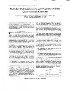
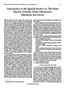
Fig. 1. The array-based method for mounting the schematic circuit, showing a half-wave diode rectifier example.
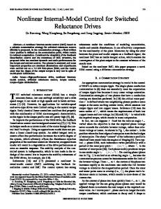
WWW-HTML-based course in basic power electronics circuits, and which are designed to be used both in the normal classes and the laboratory classes. The applets deal with the main aspects of basic uncontrolled and controlled rectifiers; they can be used to calculate important parameters such as power factor, input current total harmonic distortion, root mean square (rms) values, average and peak values, load voltage waveform with/without commutation angle, and to provide a script file to be used in the simulator package Pspice. II. DEVELOPMENT AND ORGANIZATION OF JAVA APPLETS The proposed Java applets were developed to assist power electronics education at the undergraduate level in engineering courses. The main goal of the proposed Java applets is to produce an interactive visualization of simulations of an idealized power electronics circuit in the steady state, which is used as an instructional tool embedded in a WWW-HTML-based course both in the classroom and in the laboratory. Therefore, the results of a simulation processed in steady state may be visually presented to learners in real time, illustrating important concepts that are difficult to be show in traditional classes and laboratories. These Java applets, which were previously developed and published in [16]–[18], had the creation of an easy and flexible environment to study and learn power electronics as an initial goal. In this new development stage, the objectives were to improve the programming methods (classes, interfaces, and heritage) to facilitate the tool’s maintenance and updating and the development of novel Java applets providing a more complete environment to serve the needs of power electronics courses. For instance, Fig. 1 shows, in a simplified way, how the schematic circuits have been mounted over the new applets, and Fig. 2 shows a comparison between previous and new Java applet applications. The graphical user interfaces (GUIs) for the simulation applets were designed with four distinct sectors, shown in Fig. 3, to give the student an easy and straightforward way to go through menu options to change circuit parameters and to run and view simulation results.
Fig. 2. A comparison between the previous version and the new version of Java applet applications. (a) Old version. (b) New version.
Fig. 3. Graphical user interface designed for the simulation applets.
Some sectors that can initiate new simulations are described as active, and the rest are passive. The passive sectors provide the feedback information to the student through waveforms and calculated values. Sectors 1 and 2 are active. In these sectors, the student can specify all the circuit parameters and select any desired component of the circuit upon which to perform the required simulation analysis. Essentially, the student can set the load type (R or
582
IEEE TRANSACTIONS ON EDUCATION, VOL. 53, NO. 4, NOVEMBER 2010
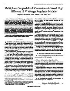
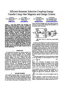
Fig. 4. Single-phase full-bridge controlled rectifier: “Graphic” guide, “Puschlowski” abacus.
Fig. 5. Single-phase half-wave uncontrolled rectifier: waveforms for the resistive-inductive load.
R-L) and the magnitudes, amplitude, and frequency of the input voltage, and the fire angle in the case of controlled rectifiers. Sector 2 is a circuit schematic drawing module (CSDM). Its structure is based on a 5 7 array. The circuit is created by considering values/attributes in the array (rows and columns). A database was developed containing information on layout, orientation, position, and numeric codes for the components. In addition, the CSDM module is interconnected with waveforms and the main modules, and it receives parameters from the operational stages and shows the current flowing through the circuit’s paths. Sectors 3 and 4 are passive sectors. The voltage and current waveforms for the circuit component selected in the sector 2 are shown in sector 3. This sector is connected with sector 4 and the abacus module. The user can modify parameters either directly in sector 1 or indirectly using the abacus waveform located in “Graphic” guide. The abacus module draws the “Puschlowski” abacus for the selected topologic structure and provides a drag-able cursor on the abacus graphic. The parameters of sector 1 can therefore be modified dynamically and easily using the mouse, as shown in Fig. 4. It should be noted that in the old Java applet applications, the main values shown in sector 4 were computed using the basic equations of each rectifier structure. In the new Java applets, sector 4 receives voltage and current waveforms from sector 3 and computes their peak, rms, and average values through the Fourier series algorithm. Furthermore, sector 3 allows the visualization of the input current harmonic content using the “Analysis” guide option. Additionally, if inconsistent values were specified by the students in the simulation options, warnings will appear in the passive sectors, giving the cause of the error.
A. Uncontrolled Rectifiers (Idealized Circuits)
III. DEVELOPED JAVA APPLETS Currently, the available interactive circuit simulations include the following.
• Single-phase: half-wave diode rectifier, half-wave diode rectifier with freewheeling diode, full-wave center-tapped diode rectifier, and full-wave full-bridge diode rectifier. • Three-phase: three-pulse diode rectifier and six-pulse fullbridge diode rectifier. B. Controlled Rectifiers (Idealized Circuits) • Single-Phase: half-wave thyristor rectifier, half-wave thyristor rectifier with freewheeling diode, full-wave center-tapped thyristor rectifier, full-wave full-bridge thyristor rectifier, and semi-controlled thyristor/diodebridge rectifier. • Three-Phase: three-pulse thyristor rectifier, six-pulse full-bridge thyristor rectifier, and semi-controlled thyristor/diode-bridge rectifier. As examples, Figs. 4–9 show two rectifier simulations performed using the proposed interactive simulation tools. Using the proposed educational tools, students can vary the circuit parameters and immediately see the effect of these changes on the main circuit variables. Therefore, the output current and voltage waveforms, as well as some rms, average, and peak circuit values, can be investigated in the simulation applets for different input parameters, as shown in Figs. 4 and 5. Fig. 4 shows an example of abacus module interaction, in this case the “Puschlowski” abacus, for the single-phase full-bridge controlled rectifier. The tool draws some waveforms for dif, allowing visualization of the cirferent load angle values cuit’s operational limits. It also draws, in boldface, the abacus for the load angle specified for the simulation. Additionally, two drag-able cursors are available in the boldface abacus. The left one allows the load angle to be varied, and the right cursor alto be varied, according to load angle and lows the fire angle . extinction current angle Moreover, additional features for the proposed improved simulation applets include a Fourier analysis option for some specified circuit variables, an animation mode showing the operational stages along with the current flow paths, a waveform
CANESIN et al.: SIMULATION TOOLS FOR POWER ELECTRONICS COURSES BASED ON JAVA TECHNOLOGIES
Fig. 6. Three-phase semi-controlled thyristor/diode-bridge rectifier, example of operational stages using “Move cursor” option.
zoom tool with cursor option, an abacus mode where the students can select the rectifier operation point through normalized graphics, and a Pspice option where the simulation net-list script for the interactive simulation is provided using the Pspice standard. Fig. 6 shows an example illustrating the option “move cursor”; when this option is selected and the point indicating the current waveform position is dragged by the mouse, the actual amplitudes of current and voltage are shown at the bottom of Section 3, and the current flow path is shown in the power circuit picture (sector 2). The current flow can be visualized by moving arrows. In this way, the students can pass through and analyze all the topological stages of the rectifier topology. Another available option is the “anime mode” that provides the same information on the topological stages, but automatically as an animation. In addition, for all the interactive simulation tools, a Fourier analysis can be performed using the input current through one of the input voltage sources or the current and voltage across the load. As shown in Fig. 7, the Fourier analysis results are presented in a table format, where the harmonic content is depicted in component order with their associated magnitudes of peak values, frequency, and the phases in degrees. Furthermore, the power factor (P.F.) and total harmonic distortion (T.H.D.) for the input current can be also computed. In order to validate the developed simulation models, the results were compared with the results obtained from a well-known simulator package, Pspice, where the rectifier circuits were created by employing idealized models for the semiconductors and simulated using the script file provided by the Java application, as shown in the example of Fig. 8. Semiconductor devices cannot turn on and turn off instantaneously if there are series inductances with the input voltage sources. Therefore, the “Commutation” guide allows the visualization of the series inductance effects. Through sector 3, this module receives the waveform and estimates the average voltage drop in the load, showing the load voltage waveform considering the nonnull commutation angle. Additionally, in this module, one can insert parameters such as commutation
583
Fig. 7. Single-phase half-wave controlled rectifier with freewheeling diode, example of input current harmonic analysis.
Fig. 8. Single-phase semi-controlled thyristor/diode-bridge rectifier, Pspice script example.
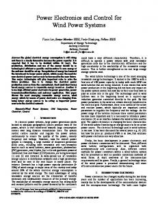
angle or series inductance in order to estimate the voltage drop in the load, as shown in Fig. 9. Fig. 10 shows the comparison of the results for the singlephase semi-controlled thyristor/diode-bridge rectifier. The relatively small differences between the results obtained, shown in Tables I and II, indicate that the simulation applet error was relatively small and that it is reasonably accurate, taking into account the simplicity of the algorithms used and the errors in converting pixels to voltage or current for magnitude values. IV. WWW COURSE The complete platform for use in power electronics classes includes new online content over the Web, through an open and distributed environment. This WWW course platform allows free access to all available Java applets and provides all the class material, including exercises and set problems. Therefore, any user can study the content through the Internet and can transfer online contents to their personal computer using freely available tools anywhere at any time.
584
IEEE TRANSACTIONS ON EDUCATION, VOL. 53, NO. 4, NOVEMBER 2010
TABLE I OUTPUT VOLTAGE AND TOTAL HARMONIC DISTORTION ANALYSIS
TABLE II MAIN VOLTAGE AND CURRENT VALUES ANALYSIS Fig. 9. Three-phase six-pulse full-bridge controlled rectifier, commutation analysis example (series inductances).
Each course chapter and its topics can be instantaneously accessed by the user, including the connected tools and Java applets for simulations. The courseware platform for all chapters has downloadable tools including available exercise lists, classes notes, and other related topics. V. SIMULATION AND LABORATORY
Fig. 10. Single-phase semi-controlled thyristor/diode-bridge rectifier: Pspice results versus Java applet results. (a) Pspice waveforms. (b) Simulation applet.
Currently, on the actual platform, only the content to “Power Electronics I” course is available, in Portuguese. It should be noticed that all content was developed using open tools such as the PHP language and MySQL database. All content is therefore interconnected in the database, allowing shortcuts to access several topics. In the future, this will allow some statistics related to user access to be gathered.
Since these classes were introduced, students have been able to interact with the tools described here to explore the main aspects of a converter’s operation in a user-friendly way without experiencing the problems typically encountered by novices to simulation packages (convergence problems, tolerances, etc.). In the next stage, students are requested to use net-lists provided by the proposed tools in well-known simulation packages (Pspice for example) in order to accomplish a complete analysis to improve the models and to draw a distinction between both computational approaches. The net-lists provided are based on a component models library created with the following assumptions: the voltage drop across the diode when forward biased is zero, and there are no commutation losses in the switches or in the diodes. However, these assumptions can be fairly far from reality, and the nonidealities of the real components can produce several effects on the operation of the converter, which are neglected in simplified approaches and can be complicated to incorporate even with more realistic models (Pspice) [19], [20]. In this way, some practical rectifier converter evaluations, commonly included in regular laboratory classes, could be complemented with interactive simulation tools. Consequently, students could improve their knowledge of power electronics concepts, drawing an analogy between the idealized theory pre-
CANESIN et al.: SIMULATION TOOLS FOR POWER ELECTRONICS COURSES BASED ON JAVA TECHNOLOGIES
585
TABLE III LOAD VOLTAGE ANALYSIS
Fig. 11. Experimental setup example. (a) Experimental setup. (b) DEGEM experiment board. (c) Circuitry of the experiment.
Fig. 12. Comparison between experimental and simulation results. (a) Experimental results from oscilloscope. (b) Simulation results from microcomputer using the proposed tool.
sented by proposed educational tools and practical results obtained in the laboratory. VI. LABORATORY SETUP EXAMPLE The experiments are developed using a laboratory setup including digital multimeters, a digital oscilloscope, didactic rectifier modules from DEGEM Systems, and a microcomputer with Internet connection, as shown in Fig. 11. In this context, through experimental analysis of a specific rectifier structure, students can compare and analyze the experimental results in relation to simulated results obtained from the proposed Java applets, as shown in Fig. 12. Consequently, students can develop an accurate conclusion to their experiments through a complete analysis of the idealized simulated circuits and the real experiments, confirming and proving the concepts developed in the classes. In the example shown in Fig. 12 and Table III, students can observe some nonidealities of the circuitry, such as the thyristor forward voltage drop during the interval when the thyristor operates in the on-state and the thyristor commutation-angle reduces the average value of the load voltage.
VII. CONCLUSION This paper presented novel Java applets for a WWW-HTMLbased course in power electronics, which can also be applied in power electronics experiments. Information technology offers new perspectives for education, not only with respect to the technologies themselves, but also on the philosophy of education and strategies for instruction and learning, allowing significant changes to many aspects of undergraduate education. Java applets provide a powerful and flexible way to deliver interactive content to students. In particular, the interactive simulations allow anyone to gain new insight into learning the behavior of basic rectifiers without their having any previous circuitry knowledge and without the need for either sophisticated simulation tools, such as Pspice, that are expensive and have a significant learning curve or for expensive instruments, such as an oscilloscope. A significant increase was observed in the students’ desire to learn the power electronics course content when the proposed Java tools were included in the traditional classes. This resulted in a significant improvement of their apprenticeship due to their increased motivation and their increased ability to comprehend the behavior of several rectifier circuits. In addition, the use of these proposed tools during the traditional laboratory allows students to make an online comparison analysis between their lab experiences and the theoretical concepts explored in the classes. The resultant approach is very efficient for education because the students are actively involved via an interactive and attractive learning system. Finally, the novel suite of simulation tools are available to students and teachers, free of charge, in the Power Electronics Laboratory Web page of the São Paulo State University, UNESP, and Department of Electrical Engineering-Campus of Ilha Solteira (SP)–Brazil [21].
REFERENCES [1] G. Hwang, “A tutoring strategy supporting system for distance learning on computer networks,” IEEE Trans. Educ., vol. 41, no. 4, pp. 343–343, Nov. 1998. [2] G. Bengu and W. Swart, “A computer-aided, total quality approach to manufacturing education in engineering,” IEEE Trans. Educ., vol. 39, no. 3, pp. 415–422, Aug. 1996. [3] H. A. Latchman, C. Salzmann, D. Gillet, and H. Bouzekri, “Information technology enhanced learning in distance and conventional education,” IEEE Trans. Educ., vol. 42, no. 4, pp. 247–254, Nov. 1999. [4] A. A. Renshaw, J. H. Reinbel, C. A. Zukowski, K. Penn, R. O. McClintock, and M. B. Friedman, “An assessment of online engineering design problem presentation strategies,” IEEE Trans. Educ., vol. 43, no. 2, pp. 83–91, May 2000. [5] M. J. Wirthlin and B. McMurtrey, “Web-based IP evaluation and distribution using applets,” IEEE Trans. Comput.-Aided Design Integr. Circuits Syst., vol. 22, no. 8, pp. 985–994, Aug. 2003.
586
IEEE TRANSACTIONS ON EDUCATION, VOL. 53, NO. 4, NOVEMBER 2010
[6] V. G. Agelidis, “The future of power electronics/power engineering education: Challenges and opportunities,” in Proc. IEEE Power Electron. Educ. Workshop, Recife, Brazil, 2005, vol. 1, pp. 1–8. [7] D. W. Hart, “Circuit simulation as an aid in teaching the principles of power electronics,” IEEE Trans. Educ., vol. 36, no. 1, pp. 10–16, Feb. 1993. [8] I. Chamas and M. A. El Nokali, “Automated Pspice simulation as an effective design tool in teaching power electronics,” IEEE Trans. Educ., vol. 47, no. 3, pp. 415–421, Aug. 2004. [9] V. Ramaswamy, “Power electronics online text,” Oct. 23, 2009 [Online]. Available: http://services.eng.uts.edu.au/~venkat/pe_html/ peintro.htm [10] U. Drofenik and J. W. Kolar, “Interactive power electronics seminar (iPES)-a Web-based introductory power electronics course employing Java applets,” in Proc. IEEE Annu. Power Electron. Specialists Conf., Cairns, Australia, 2002, vol. 2, pp. 443–448. [11] M. H. Todorovic, L. Palma, and P. Enjeti, “Development of new Webbased materials to teach power electronics courses,” in Proc. IEEE Power Electron. Educ. Workshop, Recife, Brazil, 2005, vol. 1, pp. 9–14. [12] P. Bauer, B. Davat, V. Fedak, and V. Hajek, “Educational visualization for teaching power electronics,” in Proc. IEEE Power Electron. Educ. Workshop, Recife, Brazil, 2005, vol. 1, pp. 45–51. [13] S. Harb, K. Kalaldeh, A. Harb, and I. Batarseh, “Interactive Java applets for power electronics e-learning,” in Proc. IEEE Power Electron. Educ. Workshop, Recife, Brazil, 2005, vol. 1, pp. 26–33. [14] C. Fernández, O. Garcia, J. A. Cobos, and J. Uceda, “Self-learning laboratory set-up for teaching power electronics combining simulations and measurements,” in Proc. IEEE Annu. Power Electron. Specialists Conf., Cairns, Australia, 2002, vol. 2, pp. 449–454. [15] R. S. Balog, Z. Sorchini, J. W. Kimball, P. L. Chapman, and P. T. Krein, “Modern laboratory-based education for power electronics and electric machines,” IEEE Trans. Power Syst., vol. 20, no. 2, pp. 538–547, May 2005. [16] F. A. S. Gonçalves and C. A. Canesin, “Java applets for a WWWHTML-based course in power electronics,” in Proc. IEEE Annu. Power Electron. Specialists Conf., Vancouver, BC, Canada, 2001, vol. 1, pp. 85–90. [17] C. A. Canesin and F. A. S. Gonçalves, “Educational Java applets get in power electronics labs,” in Proc. IEEE Power Electron. Educ. Workshop, Recife, Brazil, 2005, vol. 1, pp. 34–39. [18] C. A. Canesin, F. A. S. Gonçalves, and L. P. Sampaio, “Interactive Java applets for power electronics education,” in Proc. 9th Brazilian Power Electron. Conf., Blumenau, Brazil, 2007, vol. 1, pp. 989–994. [19] N. Mohan, T. M. Undeland, and W. P. Robbins, Power Electronics: Converters, Applications, and Design, 2nd ed. New York: Wiley, 1995.
[20] M. H. Rashid and H. M. Rashid, SPICE for Power Electronics and Electric Power, 2nd ed. Boca Raton, FL: CRC Press, 2006. [21] F. A. S. Gonçalves, C. A. Canesin, and L. P. Sampaio, “Interactive simulation tools for power electronics,” Oct. 23, 2009 [Online]. Available: http://www.dee.feis.unesp.br/docentes/flavio/lepjava
Carlos A. Canesin received the B.S. degree from São Paulo State University, Ilha Solteira (SP), Brazil, in 1984, and the M.S. and Ph.D. degrees from the Federal University of Santa Catarina—Power Electronics Institute, Florianópolis (SC), Brazil, in 1990 and 1996, respectively, all in electrical engineering. He started the Power Electronics Laboratory (LEP) at the São Paulo State University, UNESP-FEIS, where he is currently a Full Professor. His interests include soft-switching techniques, dc-to-dc converters, switching-mode power supplies, solar/photovoltaic energy applications, electronic fluorescent ballasts, active power-factor correction techniques, and modern educational tools for power electronics. Prof. Canesin was Editor-in-Chief of the Brazilian Journal of Power Electronics and Vice President and President of the Brazilian Power Electronics Society (SOBRAEP). Currently, he is an Associate Editor for the IEEE TRANSACTIONS ON POWER ELECTRONICS, a Member of the Editorial Council of the Brazilian Journal of Power Electronics, and permanent Member of the Deliberative Council of SOBRAEP.
Flávio Alessandro Serrão Gonçalves received the B.S., M.S., and Ph.D. degrees in electrical engineering from São Paulo State University, Ilha Solteira (SP), Brazil, in 1998, 2001, and 2005, respectively. He is currently an Assistant Professor at São Paulo State University. His interests include soft-switching techniques, dc-to-dc converters, switching-mode power supplies, digital control techniques using FPGAs and DSPs, active power-factor correction techniques, and educational tools for power electronics.
Leonardo Poltronieri Sampaio was born in São José do Rio Preto, SP, Brazil, in 1983. He received the B.S. degree in electrical engineering from São Paulo State University, Ilha Solteira (SP), Brazil, in 2008. He is currently pursuing the M.S. degree in electrical engineering at the Power Electronics Laboratory of São Paulo State University. His interests include computer programming, education in power electronics, e-learning, dc-to-dc converters, solar/photovoltaic energy applications, education tools, Java, and Linux.