Small-scale Monitoring System on LabVIEW Platform Rahmat Sanudin, Member, IEEE, Wong Kang Huei, Ida Laila Ahmad, Marlia Morsin and Muhammad Suhaimi Sulong, Member, IEEE
Abstract—A simple, effective peer-to-peer networking has been developed in this paper. It serves the purpose of a twoway communication between a host and remote terminals including as an image feeder. The communication establishment is realized by means of the Laboratory Virtual Instrumentation Engineering Workbench (LabVIEW) software and internet protocol (IP) as well as the physical connection between two terminals. The system enables the user to have monitoring and control capability through the image capture and text communication. It is concluded that the system has provide an effective, low-cost way to have a monitoring and control capability in a small scale application.
I. INTRODUCTION
T
HE concept of control and monitoring has been ongoing for the last decade. It is used to control the operation on another side and to monitor the progress of the process itself. The interest in developing such system is to take the advantages of the system, such as remote control and monitoring in highly hazardous environment. In fact, the system can be integrated with a robot manipulator to enhance the capability. It is expected that the remote control and monitoring system will become important in the future. The capability that being offered by this system is very important to improve the existing control system in the industry. In this paper, a simple, small-scale two-way communication is proposed to serve a purpose of remote monitoring. It is built on LabVIEW platform, developed by National Instrument (NI), and applies host-client interrelation concept. Section II presents the related work that has been developed on remote monitoring followed the methodology used in developing the system in Section III. Section IV presents the result, which is the capture of image and text exchange between host and client terminals. Finally, the conclusion is presented in the final section of this paper. II. RELATED WORK Monitoring system is closely related to the information and communication technology (ICT). Such system is implemented to power metering technology [1], [2]. This system is merged between automated meter reading (AMR) Manuscript received April 15, 2009. This work was supported in part by the Universiti Tun Hussein Onn Malaysia. Rahmat Sanudin, Ida Laila Ahmad, Marlia Morsin and Muhammad Suhaimi Sulong are with Faculty of Electrical and Electronic Engineering, Universiti Tun Hussein Onn Malaysia (corresponding e-mail:
[email protected]). Wong Kang Huei is an undergraduate student at Faculty of Electrical and Electronic Engineering, Universiti Tun Hussein Onn Malaysia.
or Power Quality and power usage (PQ) monitoring systems. These systems are accomplished either with automatic dialup, networked systems with automatic power flow, power usage, or long term data management with trending and automatic report generation. The concept is also widely applied in health industry, for example it is used for emergency monitoring as part of human support network system [3]. The challenge is to provide an emergency detector without compromising the privacy of the patient and it fulfills the objective by detecting the breathing condition of the patient continuously. Another application is using a Zigbee network in health monitoring system [4], [5]. It is developed to cater health care by allowing prompt, secure, low power, and low-cost health monitoring with realtime medical data transmission and update via the session initiation protocol (SIP). The system includes a wireless ECG sensor, ECG console, a Zigbee module, a SIP registrar and proxy server, a database server, and wireless devices for users. Monitoring system is also developed to detect diseases in gastro-intestinal tract by detecting variation of a pressure signal of the gastro-intestinal tract [9]. It is found that each of the each organ has its own characterized pressure fluctuation. In power system, monitoring system also has been applied such as in large induction machine [6]. It is used to predict possible fault condition in order to increase reliability and reduce catastrophic failures. In another application, an online monitoring for transformer has been developed [10], [13]. It consists of wide-band signal detector, A/D converter and cascaded lattice notch filter. It is found the system is working perfectly fine even in noisy condition due to its capability to reject noise. In fact, the interrelation with the economy is inseparable with introduction of electricity market monitoring system [8], [15]. It provides the references for market participants making strategic decisions and to foresee the market evolution. Besides, this system will help provide a reliable and fair competing playground for market players and lower electricity prices for consumers. Urban sewage treatment system, one of most important service, also applied remote monitoring system. Internetbased of such system is proposed [7] and it is found to run steadily and reliably with cost is kept at minimum level. The system helps to decrease abruptly happening system fault, shorten preparing time and repairing time, depress labor intensity and increase productivity. In manufacturing, monitoring system also has came into picture, for example remote monitoring system for factory
automation[11], which consists of a manufacturing line monitoring system and a remote programmable logic controller (PLC) monitoring using Web browser. Another application of monitoring systems includes providing information about various aspects of hazardous workplaces such as a coal mine [12]. Environmental monitoring and machine monitoring are two important applications of monitoring systems to coal mines. Finally, the monitoring concept is being implemented in digital system design and manufacturing [14], [16] – [18]. It is worked effectively to cater the needs of remote sensing, monitoring and on-line fault diagnosis for equipment or system design. It also reduces the contamination caused by room environment, gases, and process liquids; which leads to high yield and reliability in integrated circuit (IC) manufacturing [18].
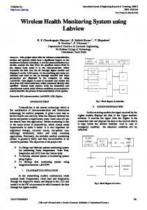
Figure 2 shows the block diagram of camera setup in LabVIEW. The block diagram will detect a web camera connected to PC through “IMAQ USB Grab Setup” followed by displaying image captured by the web camera on the monitor through “IMAQ Create VI”.
III. METHODOLOGY The system development can be divided into three different parts; camera design, web interface and physical setup. The development process is shown in Figure 1.
Fig. 2. Block diagram of camera setup
The second part is to develop a web interface between two terminals. This paper used a tool in LabVIEW called Web Publishing Tool to perform the intended interface. The web configuration needed in this process include the setting of port number, root directory for server of Hyper Text Markup Language (HTML) files, reading timeout and log file activation. Figure 3 shows the IP assignment on both host and client terminal.
Fig. 1. Flow chart of system development
The camera design needs two sub-components of LabVIEW to be installed; which are the NI Vision Development Module and NI IMAQ that are dedicated for web camera. The NI Vision Development Module enables the user to enhance images, check for presence, locate features, identify object and measure parts. NI IMAQ is used to acquire and set properties of a Universal Serial Bus (USB) camera. Its function is also used to integrate the DirectShow function provided by the camera. Both NI Vision Development Module and NI IMAQ are built-in subfunctions of LabVIEW and accessed through its library.
Fig. 3. IP assignment on host terminal
This process also needs the user to specify a unique Uniform Resource Locator (URL), which is used to log into the communication line. The URL, in turn, could be used by any computer to access the control network. The user must set the remote control is granted when a proper connection has been established. The process in URL configuration using Web Publishing Tools is depicted in Figure 4.
Fig. 6. TCP/IP sends and request VI Fig. 4. URL configuration using Web Publishing Tools
Final part is to establish physical setup of the network via Transmission Control Protocol and Internet Protocol (TCP/IP). LabVIEW has built-in VI module of TCP/IP to perform such function. In the TCP/IP module of LabVIEW, a user could have sub-functions such as TCP Create Listener, TCP Listen, TCP Open Connection and TCP Wait Listener. Figure 5 depicts the block diagram of “TCP/IP Open and Request” VI which is used to set the correct IP in order to start a two-way communication between host and client terminal. Figure 6 shows the block diagram of “TCP/IP sends and request VI” which is to perform a twoway communication between two terminals in form of text. There is a camera installed in each terminal to capture images and can be fed in two-way communication. It means both terminals are able to see the image on the other side from their own terminal.
IV. RESULT AND DISCUSSION Figure 7 and Figure 8show the image captured from client terminal and host terminal respectively. The difference in image quality between those figures is due to different quality of web camera being used. The two-way image feeder in this system enables users at both ends to have video interaction between them. Thus, the users could communicate interactively using this system.
Fig. 7. Image captured at host terminal and fed to client terminal
Fig. 5. TCP/IP Open and Request VI
Fig. 8. Image captured at client terminal and fed to host terminal
Figure 9 and Figure 10 shows the front panel on both host and client terminal respectively as displayed on the web. Note that the URL address on the web is the same being set in Web Publishing Tools.
Fig. 9. Text communication displayed on host terminal
Fig. 9. Image on host terminal
Fig. 10. Text communication displayed on client terminal
Fig. 10. Image on client terminal
Figure 11 and Figure 12 show the capture of front panel on host terminal and client terminal respectively during text communication. In this figure, the text is being sent from host computer to client computer. The ‘Buffer Out’ text box is used to compose text to be sent whereas the “Console’ text box is used to display the text received from other terminals. There is also an IP address shown on both terminals that define the communication line.
The result presented shows that the communication network developed enable users to see image and text being sent to their own terminals. On the other hand, they are also able to send image and text to the other terminals as well. It means that this monitoring system allow both parties to exchange information over the communication line remotely. The only concern of this system is that the physical connection should be reliable enough to avoid communication disruption. V. CONCLUSION This paper managed to show the development of a smallscale, low-cost monitoring system between two terminals. The system is able to feed image in two-way communication, on top of sending message between them. The features may look simple, but the applications vary. For example, it can be used for long-distance learning in which the student and lecturer can have an interactive discussion over the Internet. It also can be used in monitoring a certain process in highly hazardous area in which the user can supervise the process remotely without expose himself in a dangerous environment. Thus, this remote system is useful to be applied in the industry as well for the education purposes.
ACKNOWLEDGMENT The authors would like to thank UTHM for the facilities and technical support during the system development. REFERENCES [1] [2] [3] [4]
[5] [6]
[7] [8]
[9]
[10]
[11]
[12] [13]
[14] [15] [16]
[17] [18]
T. Chandler, The Technology Development of Automatic Metering and Monitoring Systems, The 7th International Power Engineering Conference, 2005. S.-H. Haung, W.-J. Lee, S.-P. Wang, J.-H. Chen, C.-H. Hsu, Webbased real time power system dynamic performance monitoring system, Industry Applications Conference, 2005. S. Hata, A. Nagatomo, K. Tsukamoto, Y. Mihara, Wide range 3-D vision sensor for bed monitoring system. Proceedings of the 2002 IEEE International Symposium on Industrial Electronics, 2002. Bonam Kim; Youngjoon Kim; InSung Lee; Ilsun You;Design and Implementation of a Ubiquitous ECG Monitoring System Using SIP and the Zigbee Network. Future Generation Communication and Networking (FGCN 2007). Yongming Yang; Xiaobo Huang; Xinghuo Yu; Real-Time ECG Monitoring System Based on FPGA. 33rd Annual Conference of the IEEE Industrial Electronics Society 2007. D.J.T. Siyambalapitiya, P.G. McLaren, Reliability improvement and economic benefits of online monitoring systems for large induction machines. IEEE Transactions on Industry Applications, 26(6), pp. 1018 – 1025. Zhen Zhu; Jiacun Liu; Remote monitoring system of urban sewage treatment based on Internet. IEEE International Conference on. Automation and Logistics, 2008. Gao, C.; Bompard, E.; Napoli, R.; Zhou, J.; Design of the electricity market monitoring system. Third International Conference on Electric Utility Deregulation and Restructuring and Power Technologies, 2008. Youngin Kim; Geunho Lee; Sukho Park; Byungkyu Kim; Jong-Oh Park; Jin-ho Cho; Pressure Monitoring System in Gastro-Intestinal Tract Proceedings of the 2005 IEEE International Conference on. Robotics and Automation, 2005. Li Jian; Du Lin; Sun Caixin; Liao Ruijin; Chen Weigen; A practical PD online monitoring system used for transformers. Proceedings of 2001 International Symposium on Electrical Insulating Materials, 2001. K. Kusunoki, I. Imai, H. Ohtani, T. Nakakawaji, M. Ohshima, K. Ushijima, A CORBA-based remote monitoring system for factory automation. Proceedings. 1998 First International Symposium on. Object-Oriented Real-Time Distributed Computing, 1998. R.S. Raman, R.S., Jr. Nutter, Y.V., Jr. Reddy, A production system for intelligent monitoring systems IEEE Transactions on Industry Applications, 24(5), pp. 862 – 865. Rosner, M.; Weenen, J.; Xu Hao; Benefits of comprehensive and interactive on-line monitoring and expert systems for power transformers. International Conference on Condition Monitoring and Diagnosis, 2008. Zhen Zhu; Ruchun Cui; Remote Intelligent Monitoring System Based on Embedded Internet Technology. IEEE International Conference on. Automation and Logistics, 2007. Jian Yang, A market monitoring system for the open electricity markets. IEEE Power Engineering Society Summer Meeting, 2001. Ke Cui; Zhenwei Wu; Research and implementation of remote monitoring system based on real-time uClinux. Proceedings of 2005 International Conference on. Services Systems and Services Management, 2005. Yimei Jia; Fuheng Su; Jun Liu; An on-line insulation monitoring system based on fieldbus. Electrical Insulating Materials, 2001. (ISEIM 2001). Proceedings of 2001 International Symposium on. A.W. Quick, J. Lucas, VLSI process monitoring system IEEE/SEMI International Semiconductor Manufacturing Science Symposium, 1991.