Abstractâ Snow avalanche is one of the most life-claiming calamities in the ..... http://www.avalanche.org/moonstone/forecasting/snow%20avalanches.htm).
Snow Avalanche: Study and Detection using Remote Sensing Techniques Ankit Chadha1, Aman Chadha2 and Neha Satam3 Department of Electronics and Telecommunication Engineering, Vidyalankar Institute of Technology, Mumbai, India 2 Department of Electronics and Telecommunication Engineering, University of Mumbai, Mumbai, India 1,3
Abstract— Snow avalanche is one of the most life-claiming calamities in the world. In avalancheprone regions, it is necessary to alert the population about such events beforehand to abate the effects. Hence it is important to build a snow avalanche detection system which will also detect landslides. To understand how an avalanche is started, snow physics needs to be understood which describes us about types of snow avalanche. If the snow is loose then possibility of snow-slide is more which depends on some of the parameters such as depth and character of old and new snow, moisture content, precipitation intensity and some environmental factors such as wind action and temperature, as described in this paper. It also lists some of the state-of-the-art instruments used in avalanche detection and some employing acoustic nature of avalanche. Wireless sensor nodes can be used as they are low power devices and can be adapted to suit the intended application. Finally, we brief about implementation using ZigBee and tabulate some of the popular wireless sensor nodes and their features which can be used for the same. Keywords— snow avalanche, infrasound monitor, snow crystals, remote sensing, wireless sensor nodes, ZigBee I. INTRODUCTION Avalanches rank among the most significant natural hazards in the snow-covered mountains of the world – including the populated Alpine region. The formation of avalanches depends largely on the characteristics of the snowpack. The complex microstructure of snow and the spatial variation in layer properties, however, impose limits on the forecasting of avalanche activity. Today the avalanche problem is greater than ever, because we are providing the tidal waves of snow with ever more numerous and valuable targets: railroads and all-year highways, pipe lines and power lines, reclamation projects, logging operations and mines. Within the last decade skiing has lured into the mountains a greater horde of people than Gold Rush days ever saw. Avalanche research is therefore a matter of more than purely academic interest. Perhaps the most striking recent illustration of its practical importance is the fact that transcontinental television did not become a reality until a way was found to solve an avalanche problem at the site of a microwave relay station in Nevada. The safety of increasing numbers of people and enterprises depends upon avalanche studies. The avalanche areas of India lay along the northern part of Himalayan states, viz., Jammu and Kashmir, Himachal Pradesh, Uttarakhand and Sikkim [1]. The largest number of accidents occurs on the Greater-Himalaya range. In only three states, Jammu and Kashmir, Himachal Pradesh and Uttarakhand there are 216 settlements and 11 major roads under avalanche prone slopes. Avalanche protection measures seek as far as possible to shield people, settlements and infrastructure against avalanches. A distinction is made between structural, planning and temporary
DOI : 10.23883/IJRTER.2017.3097.YNYR8
11
International Journal of Recent Trends in Engineering & Research (IJRTER) Volume 03, Issue 04; April - 2017 [ISSN: 2455-1457]
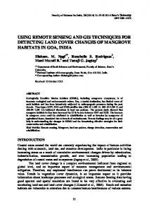
measures to protect against avalanches. Life in the avalanche-prone regions like Alps would be inconceivable without avalanche protection. II. AVALANCHE SNOW PHYSICS Formation of an avalanche largely depends on the type of snow. Avalanches are mainly of two types: Loose snow avalanche and Slab avalanche [2]. Loose snow avalanches start at or near the surface and they usually involve only surface or near-surface snow. These start at a single point and spread out as they move down along the slope of a mountain in a triangular pattern as more snow is pushed down the slope. The two most important pre-requisites for the formation of loose snow avalanches are (a) the snow is in weak cohesion, and (b) it is lying on a steep slope. When the above two conditions are prevailing, a small crystal/grain of snow loses contact with its neighboring counterpart due to lack of cohesion and gathers mass and momentum. As the particle descends with increased mass, it disturbs other crystals/grains which also start moving down with the already moving snow mass. The motion continues as long as the movement is on steep slopes. The avalanche comes to a halt once it reaches flat ground where its kinetic energy is absorbed into frictional energy. Loose snow avalanches trigger when a force, sufficient to overcome the internal cohesion and frictional resistance, is applied. This may be due to falling of stones in the formation zone, falling of lumps of snow from the tress in the formation zone, shock waves due to explosives or otherwise, movement of skiers, etc. Snow of loose cohesion may be either dry or wet, but the important point with respect to water content is that wet loose snow avalanches can be much more massive than the dry ones. For either dry or wet loose avalanches the basic mechanism is the same. The failure or separation of a snow slab lying on a slope and its downward descent with high momentum is known as slab avalanche. Snow slab is a cohesive layer of snow with a thinner, weaker failure layer beneath it. A snow slab becomes a slab avalanche once it is cut out around all boundaries by fracture. It is initiated by a failure at depth in snow cover, ultimately resulting in the movement of a block of snow. The zone demarcating the ruptured snow and the unruptured snow on the slope takes the form of a zig-zag line. The three pre-requisites for the formation of slab avalanches are: (a) the snow has had time to gain cohesion, (b) it has gained some strength, and (c) it is lying on a steep slope. Slab avalanches occur when either there is increase in stress and there is decrease in strength or there is simultaneous increase in stress and decrease in strength. Figure 1 and Table 1 summarize the classification of avalanches and their features. Slab avalanches could be dry or wet slab avalanches. Dry slab avalanches occur in the early part of winter and during peak winter when fallen snow crystal undergoes equi-temperature (ET) metamorphism or temperature gradient (TG) metamorphism under sustained sub-zero temperature. Wet snow avalanches generally occur in the later part of the winter when slab is subject to above zero degree Celsius temperature which causes formation of thin water film around the crystal, thereby making the snow slab wet. Snow Avalanches
Slab Avalanches
Dry Slabs
Loose Snow Avalanches
Wet Slabs Fig.1: Classification of snow avalanches
@IJRTER-2017, All Rights Reserved
12
International Journal of Recent Trends in Engineering & Research (IJRTER) Volume 03, Issue 04; April - 2017 [ISSN: 2455-1457] Table 1: Features of Snow avalanche
Parameters Slab Avalanche Pre-requisite for The snow has had time to gain cohesion formation It has gained some strength It is lying on a steep slope Starting point Starts when snow slab is cut out around all boundaries by fracture and initiated by failure at depth in snow cover Triggered when Force, large enough to overcome internal cohesion and frictional resistance, is applied
Loose Snow Avalanche Snow is in weak cohesion Snow is lying on a steep slope Start at or near surface and spread out in triangular pattern Stress is increased and strength is decreased
As per Trautman, processes leading to wet-snow avalanches are complex and the conditions of the snowpack may change from stable to unstable in the range of hours. The presence of liquid water within the snowpack in the starting zone is a prerequisite and several field campaigns and experiments under laboratory conditions found decreasing shear strength with increasing liquid water content. However, quantifying the amount of liquid water within the snowpack is a difficult task. III. AVALANCHE All avalanches can be divided into two general classifications: loose snow and packed snow. The two classes are basically different in the way they start and develop and in the kind of hazard they pose. An avalanche of loose snow always starts on the surface from a point or a narrow sector. From the starting point it grows fanwise, expanding both in width and depth. The speed and nature of its development depends on whether the snow is dry, damp or wet. If the snow is dry, its particles are quickly pulverized and form a cloud of frigid snow dust, so that the avalanche travels as much in the air as on the ground. It moves at high speed. Unless it is very large, this kind of avalanche is not particularly destructive, but a person caught in one can die of suffocation. An avalanche of loose snow which is damp or wet stays on the ground and moves more slowly. Its mass is many times greater than that of a dry avalanche and it is much more destructive [3]. The slow-moving but enormously heavy wet avalanches of spring are noted destroyers of property. On the other hand, a loose-snow avalanche, wet or dry, spends itself quickly and the hazard is soon over. When the slide has run its course, the snow stabilizes in place. Avalanches of packed snow behave in an altogether different manner. This kind of slide is released suddenly as a great, cohesive slab of snow. It may originate either at the surface or through the collapse of a stratum deep within the snow pack. It starts on a wide front with penetration in depth. The place where the slab has broken away from the snowpack is always marked by an angular fracture line roughly following the mountainside contour. I have seen one such fracture edge that was more than a mile long and up to eight feet deep. In a packed-snow avalanche the main body of the slide reaches its maximum speed within seconds. Thus it exerts its full destructive power from the place where it starts, whereas a loose-snow avalanche does not attain its greatest momentum until near the end of its run. Moreover, slab snow does not necessarily slide immediately after weather conditions have made it unstable. The slab may lie in an unstable condition for days, weeks or even months, during which it may be triggered at any time into an avalanche. For these reasons the slab avalanche is the most dangerous of all types. A series of slab avalanches may stabilize conditions only locally, leaving the slab on an adjacent slope as lethal as an unexploded shell. IV. FACTORS CONTRIBUTING TO AVALANCHE HAZARD The following factors have been identified universally which contribute to the avalanche hazard as given in Table 2.
@IJRTER-2017, All Rights Reserved
13
International Journal of Recent Trends in Engineering & Research (IJRTER) Volume 03, Issue 04; April - 2017 [ISSN: 2455-1457]
Table 2: Factors having a significant role in triggering snow avalanche [4]
Factor Contribution Depth of old snow on (i) If there are two feet or more, that is generally sufficient to cover the slope ground obstructions so that it becomes easier for new snow to slide over them. (ii) Also, the deeper the snow, the more ammunition it supplies to the avalanche. Character of the old (i) A loose snow surface promotes good cohesion with a fresh fall but snow surface allows deeper penetration of any avalanche that starts. (ii) A crusted or wind-packed surface means poor cohesion with the new snow but restricts the avalanche to the new layer. Depth of the new fall (i) 12 inches is regarded as the minimum generally necessary to produce by itself an avalanche of dangerous proportions. Free moisture content (ii) It acts as cement and improves cohesion, within limits. But good cohesion may be dangerous as well as helpful, for it may enable the wind to pile up greater masses of snow for release in an avalanche. (iii) The amount of free moisture in snow can be gauged by a simple test: squeezing a handful in the gloved hand. Dry snow will not pack; damp snow packs readily; wet snow becomes waterlogged and slippery. Total water content of (i) Here the most significant circumstance is a departure from the norm. the snow (ratio of water (ii) For example, dry snow types normally average 5 to 8% water, but to snow) when the proportion of water in such snow exceeds 10%, we have a clear warning that its weight may be increasing faster than its cohesion. (iii) Other factors being favorable, the outcome was an avalanche cycle of extraordinary violence. Intensity of the (i) When the snow piles up at the rate of an inch or more per hour, the snowfall (in inches of pack is growing faster than the stabilizing forces, such as settlement, can snow per hour) take care of it. (ii) Moreover, this sudden increase in load may fracture a slab beneath, just as a quick blow will snap a brittle stick which could resist the same amount of pressure if it were applied gradually. Precipitation intensity (i) It is the actual amount of water, measured in inches per hour, being deposited as snow. (ii) This measurement gives a combined image of the type, water ratio, quantity and intensity of the snowfall, plus some indication of the temperature and wind action. (iii) It is the most promising single guide to avalanche hazard yet discovered. The techniques for observing it are new. (iv) With a continuous precipitation intensity of one tenth of an inch of water or more per hour and wind action at effective levels the avalanche hazard becomes critical when the total water precipitation reaches one inch. Wind action (i) It is the most important and versatile of all. It overloads certain slopes at the expense of others; it grinds snow crystals to simpler and less cohesive forms; it con constructs stable crust and fragile slab, often side by side. (ii) Warm wind is as effective a thawing agent as rain, more effective than sunlight. By sudden changes in direction and velocity wind can act as a shearing trigger on a layer of snow it has just deposited.
@IJRTER-2017, All Rights Reserved
14
International Journal of Recent Trends in Engineering & Research (IJRTER) Volume 03, Issue 04; April - 2017 [ISSN: 2455-1457]
Temperature
Settlement of the snow
(iii) Finally, it is essential to the formation of slab in ways which we do not yet completely understand. (iv) An average velocity of about 15 miles per hour (in the mountains air currents are so erratic that they can only be sampled) is the minimum effective level for wind's action in building avalanche hazards. (i) It directly influences the snow type. Dry snows normally fall at 25 degrees Fahrenheit and below. (ii) Temperatures above 28 degrees promote rapid settlement and metamorphosis of the snow-sometimes too rapid. A sudden rise of temperature causes a loss of cohesion fast enough to trigger an avalanche. A sudden drop increases the tension, particularly in slab. (iii) The gradual warming of the temperature in the spring leads to cumulative deterioration of the snow and to heavy, wet avalanches. (i) With one exception it is always a stabilizing factor, the exception being the shrinkage of a loose snow layer away from a slab above, thus robbing the slab of support. (ii) In new snow a settlement ratio less than 15 percent indicates that little consolidation is taking place; above 80 percent, stabilization is proceeding rapidly. Over a long period ordinary snow layers shrink up to 90 percent, but slab layers may shrink no more than 60 per percent. (iii) Thus abnormally low shrinkage in a layer in indicates that a slab is forming.
Precipitation, wind direction and wind speed affect accumulation of snow and avalanches, whilst precipitation, along with thawing and ablation in the spring, affects rockfalls as well as debris flows [5]. When there is an avalanche threat in some region or on some hillside, avalanches often flow along many paths in a very short time. Monitoring the paths with the highest avalanche frequency provides information and an alert on when an avalanche has started moving down a hillside in a snowstorm. This allows avalanche hazard warnings to be issued for that hillside and at other sites with similar topography and weather conditions. V. METHODS TO PREDICT AVALANCHE Avalanche detection systems are not unique. The first such domestic avalanche detection system was designed in the mid-1950. The detection system consisted of trip wires (provides an on/off signal with the requirement that it be manual reset after an avalanche) placed in the avalanche path. The data was communicated via Radio Frequency (RF) telemetry to a stripped wall paper recorder, where personnel could monitor avalanche activity remotely. This concept was further developed to prevent train derailments [6]. These detection systems, implemented in Europe and Canada, consisted of wires along the tracks, which are broken, when snow or rocks hit the rails. Sensors have included cables with trip switches, radar, vibration, sound sensors, and photoelectric barriers. Many of these systems lack an automatic reset feature, thus requiring personnel to enter the hazardous area when the avalanche hazard is high or greater. Railroad employees were required to reset or even rewire the system after every alarm. 5.1. Using various instruments Recently, researchers and technicians in Switzerland have designed a remote avalanche warning system. This warning system consists of Doppler Radar, force measurements of cables, and geophones. Data is recorded in real time and is communicated automatically to warning lights and public phone systems [7]. At Rogers Pass, British Columbia, Canada, transportation officials are implementing an Avalanche Track Monitoring System (ATMS). This system provides real time monitoring of avalanche activity. The monitoring system is suspended from a cable tensioned between two fixed points on either side of the avalanche track. During the passage of an avalanche
@IJRTER-2017, All Rights Reserved
15
International Journal of Recent Trends in Engineering & Research (IJRTER) Volume 03, Issue 04; April - 2017 [ISSN: 2455-1457]
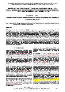
the ATMS is tilted and sends a signal, which is received by a radio or datalogger. Figure 2 shows one such instrument, special infrasound microphone ECHO which captures the infrasonic waves released during snow movement.
Fig. 2: Special infrasound microphones ECHO, installed under the snow cover [7]
The main instruments being used in measurements for detection of snow avalanche are tabulated in Table 3. Table 3: Instruments deployed in snow avalanche detection [8]
Instrument SettlementTemperature Gauge
Description and Usage (i) This instrument provides a simple and reliable means of measuring snow cover settlement throughout the winter without disturbing the snow cover. (ii) The settlement gauge is nothing more than a Wheatstone bridge, the vertical resistance wire forming one side of the bridge and the helix potentiometer the other. (iii) The resistance wire, #20 to #24-gauge nichrome, is suspended vertically in the center of a smooth, level area in the study plot, and is long enough to clear the maximum winter snow depth. (iv) Following each snowfall, a wooden lattice supporting a crocodile clip connector is placed on the snow surface and the clip attached to the resistance wire. Snow Collector (i) The measurement of snowfall or precipitation with an exposed for Recording precipitation gauge is difficult under the most favorable circumstances, and Rain Gauge especially so in mountainous terrain where wind action is strong, for the amount of snow which actually falls into the orifice of the gauge seldom bears much relation to the average amount deposited on the ground. (ii) It is under just these most difficult conditions of windy storms in the mountains that the precipitation record is of most interest to avalanche forecasting. Several methods have been tested of controlling snowfall into a recording precipitation gauge in order to obtain a chart record of precipitation intensity during snowstorms. (iii) These include such standard methods as the use of wind shields around the gauge orifice. Temperature (i) This instrument permits direct reading of air or snow temperature at long Telemeter distances from the observation point. (ii) It was developed for observing air temperature in Squaw Peak Bowl, high above the regular snow observation station on the Squaw Valley floor, but may be extended to any application where a single temperature must be measured at a distance.
@IJRTER-2017, All Rights Reserved
16
International Journal of Recent Trends in Engineering & Research (IJRTER) Volume 03, Issue 04; April - 2017 [ISSN: 2455-1457]
5.2. Using acoustic sources in avalanche Acoustic emissions in snow are displacement waves which can originate from fractures in the snow or from the frictional sliding of gliding snow or snow creeping around obstacles. The breaking of bonds between ice grains seems to be the main source of acoustic emissions in seasonal snow (St Lawrence and Brad1ey 1973). The bonds between the chain grains that connect the more rigid clusters are more highly stressed [8]. These break, and part of the released energy propagates from the broken bonds as displacement wave packets. The frequency spectra of such events are in the ultrasonic range and are determined mainly by the speed of fracture propagation in the bond ice, the bond diameter, and the resonance frequencies and dissipation of the intergranu1ar network. At low strain-rates and small strains, ductile creep can occur in the ice network and redistribute the stress at a rate which is high enough to avoid macroscopic stress concentrations. Under these conditions, the bond breaks do not aggregate, but occur independently and generate no significant low-frequency acoustic components. This behavior is typical of ductile rupture and deformation. Figure 3 is a conceptual diagram that realizes the problem and an approach to the solution. Spatially distributed monitoring nodes are utilized for recording of infrasound data which is transferred via radio telemetry to a central processing unit that performs data management, data analysis, and appropriate response actions to identified avalanche events.
Fig. 3: Conceptual diagram of avalanche infrasound monitoring [9]
Emissions from snow were made using velocity gages resonant at 28 Hz. These sensors were either mounted on concrete pads in the ground or were floated in the snowpack near avalanche starting zones. The velocity gages used for observations reported in the present paper were made with critically damped geophones resonant at 5 Hz and, more recently, with critically damped geophones resonant at 8 Hz. During their movement, most avalanches produce infrasounds, i. e. acoustic signals within approx. 1- 20 Hz. These inaudible and long-range low- frequency sounds as shown in Figure 4 [7]
@IJRTER-2017, All Rights Reserved
17
International Journal of Recent Trends in Engineering & Research (IJRTER) Volume 03, Issue 04; April - 2017 [ISSN: 2455-1457]
are suitable for automatic and real-time detection and localization of the avalanche activity over an extended area of several square km.
Fig.4: Sound waveform recorded during an experimental artificial release of avalanche [7]
Although the sensitivity of the original snow-mounted geophones was found to be better, severe problems of resonance forced their abandonment. For good acoustic coupling the density of the sensor was matched approximately to the snow. These sensors were used for the present study in Switzerland. 5.3. Using detecting systems Detecting systems have to measure movements and flows close to their origin to guaranty enough pre-warning time. Basically long range and short range detectors could fulfill this requirement. In practice long range systems, e.g. gated Doppler radars, optical, seismic or acoustical systems are less redundant (only one type of sensor), depend on weather conditions (optical systems), do not discriminate environmental noise from the true event (long range seismic) or may detect a flow too late (infrasonic and seismic systems) or are very expensive (gated long range radar). Therefore most alarm systems built worldwide are of the short range type, where the endangering event is detected with multiple sensors close or at its origin [10]. Detectors have to function in a harsh alpine environment at remote locations inaccessible for long periods of time and have to be powered by batteries and solar cells. The types of sensors depend on the processes to be measured: flows or fast movements (avalanches, mud-flows), slow dislocations (initiation process for rockfall), forces (interaction with flows), noise (sediment enriched torrent flows), and seismic signals. If a predefined level of danger is reached, an alarm is sent to the signaling system. The system often continues to measure, at increased time resolution, during the ongoing event and analyses data online. A short period (1 to 2min) after the alarm transmission, a digital status report is sent to the control- and maintenance centre. In some cases additional detecting systems are installed at the traffic line to detect a flow or debris. In such cases, if no interaction is detected within a given time interval after the alarm, the alarm may be reset automatically. Data and signal status are also sent to the control centre, where the alarm can be reset manually if necessary. In most cases the detecting system will provide information on the magnitude of the event, proposing a false alarm if it turned out that the event was not likely to reach the traffic line. If high speed snow avalanches have to be detected, the available pre-warning time is small (typically 30 to 45sec.), therefore the alarm has to be transmitted quickly within the first one to five sec. after the first detection of the flow.
@IJRTER-2017, All Rights Reserved
18
International Journal of Recent Trends in Engineering & Research (IJRTER) Volume 03, Issue 04; April - 2017 [ISSN: 2455-1457]
5.4. Using a signaling system The signaling system consists of several modules: the power module with backup batteries, the transmission- and relay module, the signal control and test module for traffic lights and sirens etc. and optional sensor interfaces for local flow- and debris detection. In its simplest configuration the RF-modem of the transmission module provides the alarm signal directly to a commercial traffic light system alternating (AC) signal. In a standard system, the control of the lights and sirens uses a CR10X with some additional hardware. This system uses much less power than a standard commercial system, allows for automatic lamp tests, and for setting and resetting signals from the control centre. VI. IMPLEMENTATION Technological advancements in recent years have enabled the development of tiny, cheap, disposable and self contained battery powered computers, known as sensor nodes or “motes”, which can accept input from an attached sensor, process this input and transmit the results wirelessly to some interested device(s). When a number of these nodes work together, conceivably up to hundreds of thousands, a Wireless Sensor Network (WSN) is formed [11]. The storage unit of the node usually consists of both flash memories, containing the program code for the node, and RAM, which stores sensed information and any data needed for computations. Some motes also have non-volatile storage for off-line data capture for later retrieval. Radio frequency (RF) communication is ideal for sensor nodes because it is not limited by line of sight and current technology allows implementation of low-power radio transceivers with data-rates and ranges scalable according to application. For environment observation and forecasting, three components are necessary: sensor stations, a distribution network, centralized processing farm [12]. Some of its characteristics are:
Centralized processing: the environment model is very computational intensive; it usually runs on a central server and process data gathered from the sensor network. High data volume: for example, nautical X-band radar can generate megabytes of data per second. QoS sensitivity: it defines the utility of the data, there is an engineering trade-off between QoS and energy constraint. Extensibility Autonomous operation
Conceptually, the communication within a sensor network can be classified into two categories: application and infrastructure. Application communication relates to the transfer of sensed data (or information obtained from it) with the goal of informing the observer about the phenomena. Within application communication, there are two models: cooperative and noncooperative. Non-cooperative sensors do not cooperate at the application level for information dissemination [13]. An example of co-operative sensing is in a clustering protocol when a clusterhead and the non-cluster-head members communicate with each other for information dissemination related to the actual phenomenon. Infrastructure communication refers to the communication needed to configure, maintain and optimize operation. More specifically, because of the ad hoc nature of sensor networks, sensors must be able to discover paths to other sensors of interest to them and to the observer regardless of sensor mobility or failure. Thus, infrastructure communication is needed to keep the network functional, ensure robust operation in dynamic environments, as well as optimize overall performance. Sensor networks require both application and infrastructure communication. The amount of required communication is highly influenced by the networking protocol used. Application communication is optimized by reporting measurements at the minimal rate that will satisfy the accuracy and delay requirements given sensor abilities and the quality of the paths between the sensors and the observer. The infrastructure communication is generated by the networking protocol in response to application requests or events in the network. Investing in infrastructure
@IJRTER-2017, All Rights Reserved
19
International Journal of Recent Trends in Engineering & Research (IJRTER) Volume 03, Issue 04; April - 2017 [ISSN: 2455-1457]
communication can reduce application traffic and optimize overall network operation. One of such wireless communication protocol is ZigBee. ZigBee is a self-organized WPAN protocol based on IEEE 802.15.4-2003 MAC and physical layer. Up to now, ZigBee Alliance has released ZigBee 1.0 and ZigBee-2006 specifications, and ZigBee-Pro version has also been completed [14]. ZigBee protocol supports star, tree, and mesh topologies. There are three types of devices in ZigBee protocol: coordinator, router, and end device [15]. A PAN only has one coordinator which is responsible for starting the network and choosing network parameters. Two end devices cannot communicate with each other.
Fig. 5: Outline of ZigBee stack architecture [16]
ZigBee protocol supports direct addressing with IEEE 64 bit address, indirect addressing, group addressing and broadcast addressing. ZigBee stack is made up of the framework for application layer and network layer as shown in Fig. 5. Network layer responds to build a network, route frames and store neighbor information etc. This layer conceptually includes two service entities: data service and the management service. The application layer framework comprises the application support sub-layer, the ZigBee device objects, and the manufacturer-defined application objects to finish point-to-point addressing, endpoint binding, and service discovering. For various commercial purposes, different types of motes are available which can be used. Table 4 compares some of these devices [17]-[20]. Similar to the need of protocol for sensor network, an operating system is needed to support different applications and run the required protocols in the background. Following factors are important while designing an operating system for sensor network [21]: • Architecture: The architecture of an OS has an influence on the size of the OS kernel as well as on the way it provides services to the application programs. Some of the well known OS architectures are the monolithic architecture, the micro-kernel architecture, the virtual machine architecture and the layered architecture.
@IJRTER-2017, All Rights Reserved
20
International Journal of Recent Trends in Engineering & Research (IJRTER) Volume 03, Issue 04; April - 2017 [ISSN: 2455-1457]
• Programming Model: There are two popular programming models provided by typical WSN OSes, namely: event driven programming and multithreaded programming. Multithreading is the application development model most familiar to programmer, but in its true sense rather resource intensive, therefore not considered well suited for resource constraint devices such as sensor nodes. Event driven programming is considered more useful for computing devices equipped with scarce resource but not considered convenient for traditional application developers. • Scheduling the Central Processing Unit (CPU): scheduling determines the order in which tasks are executed on a CPU. In traditional computer systems, the goal of a scheduler is to minimize latency, to maximize throughput and resource utilization, and to ensure fairness. The selection of an appropriate scheduling algorithm for WSNs typically depends on the nature of the application. For applications having real-time requirements, real-time scheduling algorithm must be used. For other applications, non-real-time scheduling algorithms are sufficient. Table 5 summarizes some popular operating systems for the purpose. REFERENCES [1] [2] [3] [4] [5] [6]
[7] [8] [9] [10] [11] [12] [13] [14] [15] [16] [17] [18] [19] [20] [21]
“Avalanche issue in Western Himalaya, India”, Evgeny A Podolskiy, Atsushi Sato and Jiro Komori, Seppyo, Journal of the Japanese Society of Snow and Ice, 2009, 71(6), 498–502. “Usefulness of mesoscale weather forecast for avalanche forecasting”, K. Srinivasan, A. Ganju and S. S. Sharma, Current Science, Vol. 88, No. 6, 25 March 2005, Special Section: Mountain Weather Forecasting. Swiss Federal Institute for Forest, Snow and Landscape Research (link: http://www.slf.ch/ueber/organisation/warnung_praevention/projekte/index_EN?status=abgeschlossene) American Avalanche Association, Avalanche library (link: http://www.avalanche.org/moonstone/forecasting/snow%20avalanches.htm) “Automatic detection of avalanches and debris flows by seismic methods”, Bjarni Bessason, Gı´Sli Eiri´Ksson, O´ Ðinn Tho´ Rarinsson, Andre´S Tho´ Rarinsson, Sigurður Einarsson, Journal of Glaciology, Vol. 53, No. 182, 2007, pp. 461-472. “Avalanche Hazard Reduction for Transportation Corridors Using Real-time Detection and Alarms”, Robert Rice Jr., Rand Decker, Newel Jensen, Ralph Patterson, Stanford Singer, and Clayton Sullivan , LeRoy Wells, Cold Regions Science and Technology Volume 34, Issue 1,Elsevier, February 2002, Pages 31–42. “Acoustic Detection System for Operational Avalanche Forecasting", Chritin (V.), Adam (V.), Rossi (M.) and Bolognesi (R.), Proceedings International Snow Science Workshop, Banff, Alberta, pp. 149-153, 1997. “Snow Avalanches and Acoustic Emissions”, R. A. Sommerfeld and H. Gubler, International Glaciological Society ©, Annals af Glacialagy 4, 1983 “Infrasonic monitoring of avalanche activity on Teton Pass”, Technical report by State of Wyoming Department of Transportation and US Department of Transportation Federal Highway Administration, July 2005. “Alarm Systems to Detect Avalanches, Mudflows and Rockfalls”, Hansueli Gubler, Alpine Natural Hazards Avalanche and Permafrost Development and Research Measuring and Warning System. “Wireless Sensor Node Hardware: A Review”, Michael Healy, Thomas Newe and Elfed Lewis, IEEE SENSORS 2008 Conference, pp. 621-624. “A Survey of Sensor Network Applications”, Ning Xu, “A Taxonomy of Wireless Micro-Sensor Network Models”, Sameer Tilak, Nael B. Abu-Ghazaleh and Wendi Heinzelman, ZigBee Alliance,http://www.ZigBee.org/. ZigBee Alliance, “ZigBee-Specification-2006-Download.pdf”, http://www.ZigBee.org/. “Application-Oriented Wireless Sensor Network Communication Protocols and Hardware Platforms: a Survey”, Zhongmin Pei, Zhidong Deng, Bo Yang, Xiaoliang Cheng, “A Summary Review of Wireless Sensors and Sensor Networks for Structural Health Monitoring “, Jerome P. Lynch and Kenneth J. Loh, The Shock and Vibration Digest, Vol. 38, No. 2, March 2006 91–128. “MICA: A Wireless Platform for Deeply Embedded Networks”, Jason L. Hill, David E. Culler, IEEE Micro, November December 2002. “Telos: Enabling Ultra-Low Power Wireless Research”, Joseph Polastre, Robert Szewczyk, and David Culler, Fourth International Symposium on Information Processing in Sensor Networks, 2005. “The Platforms Enabling Wireless Sensor Networks”, Jason Hill, Mike Horton, Ralph Kling, and Lakshman Krishnamurthy, Communications of the ACM - Wireless sensor networks, Volume 47 Issue 6, June 2004, Pages 41-46. “Operating Systems for Wireless Sensor Networks: A Survey”, Muhammad Omer Farooq and Thomas Kunz, Sensors 2011.
@IJRTER-2017, All Rights Reserved
21
International Journal of Recent Trends in Engineering & Research (IJRTER) Volume 03, Issue 04; April - 2017 [ISSN: 2455-1457]
Table 4: Comparison of commercial motes #
Parameters
1
Image
2 3
AT90LS8535
5 6
Year Manufacturer Processor/ Controller Bus Clock Speed
7
Prog. Memory
8 kB
8
512 B
10 11 12 13 14 15 16 17
Data Memory Current-Active Current -Sleep ADC Ext. Memory OS Transceiver Frequency Modulation Data Rate ID chip
18
Range
20
Battery
4
9
weC
Rene
1999 2000 UC Berkeley – Crossbow
Dot
2001
Atmega163L
Mica
Telos
Sunspot
Tmote Sky
Waspmote
2004
2006 Sun Microsystems
2007 Moteiv
2009 Libelium
MSP 430
AT91RM920T
MSP430F1611
ATmega1281
16 bit 8 MHz
32 bit
16 bit
8 Bit
128 KB
48 KB
4 MB
48 KB
128 KB
4 KB
10 KB
512 KB 25 mA 0.5 mA
10K 1.8-2.4mA 5.1uA
8 KB 4 mA 7.5 uA 10 bit 2 GB
2002 UC Berkeley ATmega103L
8 bit 4 MHz 16 KB
16 KB
1024 B 5 mA 4 uA 10 bit
5 uA
Tiny OS TR1000 868 / 916 MHz ASK on-off Key 10 Kbps
25uA
8 MHz
12 bit 4 M bit nesC,Tiny
ASK 40 kbps DS2401
Tiny OS CC 2420 2.4GHz O-QPSK 250 Kbps 48-bit chip
Java 2.4 GHz
60 m Coin Cell, 575 mAh
Battery (3V), 2850 mAh
@IJRTER-2017, All Rights Reserved
Battery (3V), 2850 mAh
1024 KB TinyOS 1.x, 2.0 CC 2420 2.4 GHz DSSS-QPSK 250 Kbps Outdoor:125 m Indoor: 50 m
3.7V, 720mAh Lithium-ion rechargable battery
2 X AA, 2900 mAh
Zigbee/WiFi/BT 868/ 900/ 2.4
Present 500 m / 700m / 10 km 3.3 V - 4.2V
22
International Journal of Recent Trends in Engineering & Research (IJRTER) Volume 03, Issue 04; April - 2017 [ISSN: 2455-1457]
Table 5: Operating Systems for Sensor Networks OS/ Feature
Architecture
Programming model
Scheduling
TinyOS
Monolithic
FIFO
Contiki
Modular
Primarily event Driven, support for TOS threads has been added Protothreads and events
MANTIS
Layered
Threads
NanoRK
Monolithic
Threads
LiteOS
Modular
Threads and Events
@IJRTER-2017, All Rights Reserved
Events are fired as they occur. Interrupts execute w.r.t. priority Five priority classes and further priorities in each priority class. Rate Monotonic and rate harmonized scheduling Priority based Round Robin Scheduling
Memory Management and Protection Static Memory Management with memory protection
Communication Protocol Support
Resource Sharing
Support for Realtime Applications
Active Message
Virtualization and Completion Events
No
Dynamic memory management and linking. No process address space protection.
uIP and Rime
Serialized Access
No
Dynamic memory management supported but use is discouraged, no memory protection. Static Memory Management and No memory protection
At Kernel Level COMM layer. Networking Layer is at user level. Application is free to use custom routing protocols. Socket like abstraction for networking
Through Semaphores.
To some extent at process scheduling level (Implementation of priority scheduling within different processes types) Yes
Dynamic memory management &it provides memory protection to processes.
File based communication
Serialized access through mutexes and semaphores. Priority Ceiling Algorithm is implemented Through synchronization primitives
No
23