Soft Errors in Advanced Semiconductor Devices Part I – The Three Radiation Sources Robert Baumann
Abstract— In this review article, we summarize the key distinguishing characteristics and sources of the three primary radiation mechanisms responsible for inducing soft errors in semiconductor devices and discuss methods useful for reducing the impact of the effects in final packaged parts. Index Terms—single event upset, alpha particle, cosmic ray neutron.
I.
INTRODUCTION
A
s the dimensions and operating voltages of electronic devices are reduced to satisfy the ever-increasing demand for higher density and lower power, their sensitivity to radiation increases dramatically. Radiation can, directly or indirectly, induce localized ionization events capable of upsetting internal data states. While the upset causes a data error, the circuit itself is undamaged; thus this type of event is called a “soft” error and the rate at which these events occur is called the soft error rate (SER). It has been established that SER in semiconductor devices is induced by three different types of radiation; alpha particles [1,2], high-energy neutrons from cosmic radiation [3-6], and/or the interaction of cosmic ray thermal neutrons and 10B in devices containing borophosphosilicate glass [711]. In this paper, the first of a three-part work considering the impact of soft errors in advanced semiconductor devices, we review the three distinct radiation sources and their unique charge generation characteristics. We also consider methods for reducing or eliminating the various radiation components. In the next paper in the series, we will be expanding our focus to consider how the charge generated by the three types of radiation events are collected by SRAM, DRAM, and logic devices. We will also consider technology, process, and design methods that can be used to mitigate the effects of these events. In part III, we will expand the scope further to look at characterization methodologies for determining radiation levels and accelerated testing and extrapolation, as well as consider the impact of soft errors on actual products as a function of current scaling trends and device applications.
Author is with Texas Instruments, Silicon Technology Development Group, 13560 N. Central Expressway, MS 3737, Dallas, TX 75243. Copyright (c) 2001 IEEE. Personal use of this material is permitted. However, permission to use this material for any other purposes must be obtained from the IEEE by sending a request to
[email protected].
II. ALPHA PARTICLES It is well known that a significant source of ionizing radiation in packaged devices is from alpha particles from the naturally occurring radioactive impurities in device materials. Alpha particles are one of the many radiations that can be emitted when the nucleus of an unstable isotope decays to a lower energy state. The alpha particle is composed of two neutrons and two protons - a doubly ionized helium atom (4He2+) emitted with specific kinetic energy in the range of ~ 4 - 9 MeV. The activity of a particular isotope is directly proportional to its natural abundance and inversely related to its half-life (the time required for a population of atoms to decay to one-half their original number). While there are many different radioactive isotopes, uranium and thorium (and their associated daughter products) have the highest activities of the naturally occurring radioactive species; thus, they are the dominant source of alpha particles in materials. The decay of uranium and thorium are shown with all the intermediate daughter products in table 1 and 2. It should be noted that not all daughters produce alpha particles. Some decay by emitting beta particles (electrons emitted from a nucleus as it transitions to a lower energy state). In general these beta emissions are not important for SER since at the energies they are emitted they seldom create sufficient ionization to cause a soft error. If the half-life of Table 1. The Uranium Series. Species Half-life Mode U-238 4.47x10⁹ yrs α Th-234 24.1 days β Pa-234 6.69 hrs β U-234 2.45x10⁵ yrs α Th-230 7.54x10⁴ yrs α Ra-226 1.60x10³ yrs α Rn-222 3.82 days α Po-218 3.05 min α Pb-214 26.8 min β Bi-214 19.7 min β Po-214 164 usec α Pb-210 22.3 yrs β Bi-210 5.01 days β Po-210 138.4 days α Pb-206 Stable
Energy (MeV) 4.196(77), 4.149(23)
4.774(72),4.723(28) 4.688(74),4.621(26) 4.785(95), 4.602(5) 5.490 6.002
7.687
5.305
Table 2. The Thorium Series Species Half-life Mode Th-232 1.41x10¹⁰yrs α Ra-228 5.76 yrs β Ac-228 6.13 hrs β Th-228 1.91 yrs α Ra-224 3.66 days α Rn-220 55.6 sec α Po-216 0.15 sec α Pb-212 10.64 hrs β Bi-212 60.60 min β (64) Bi-212 2.251 α(36) | | V | Po-212 0.30 usec α Pb-208 stable V Tl-208 3.05 min β Pb-208 stable
Energy (MeV) 4.016(77), 3.957(23)
5.426(71), 5.343(29) 5.686(94), 5.449(6) 6.288 6.779
6.336(57), 6.297(43)
8.785
the daughters is less than the half-life of the parent (which is usually the case for natural isotopes), then these must also be considered since, in equilibrium, the emission of alphas from a daughter product will be equal to the emission from the parent (secular equilibrium). A population of uranium-238 atoms in equilibrium emits eight different alpha particles at energies ranging from 4.1497.687 MeV and an equilibrium population of thorium-232 will emit 6 alpha particles from 4.149-7.687 MeV. It should be noted that the daughter product of thorium decay (table 2), Bi-212, has two possible decay paths – one is to decay to Po-212 with a beta emission and one is to decay into Tl208 with the emission of an alpha. Secular equilibrium is only valid if the material has not undergone any chemical separation, since under these conditions the various isotope concentrations can become depleted or enriched. Since 4500 4000 3500 Intensity (a.u.)
3000 2500 2000 1500 1000 500 0 2
4
6
8
10
Alpha Energy (MeV)
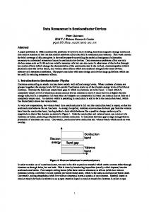
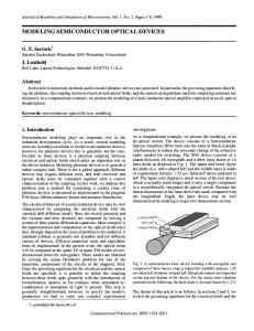
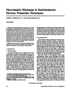
Figure 1. Alpha energy spectrum obtained from a thick foil of Th-232. Note the characteristic decay energies and the broadening due to energy loss in the film.
virtually all semiconductor materials are highly purified, in general, the alpha emitting impurities will not be in secular equilibrium. For this reason, alpha counting and spectroscopy investigations are necessary to determine the exact nature of parent/daughter distributions. An alpha energy spectrum from a thick (with respect the range of alphas in that material) metal foil of Th-232 is shown in figure 1. Distinct energy “lines” are not clearly observed since the emission can occur anywhere within the metal film – the energies listed in table 2 are broadened to lower energies since energy is lost as the alpha travels from where it was emitted to the surface. In most cases, this type of broadened distribution is what the semiconductor device will “see” in terms of incident alpha flux. The alpha spectrum from a thick source of uranium will look very similar. Thus from sources such as package mold compound or underfill which are essentially “thick” sources, a broadened alpha spectrum similar to that in figure 1 is expected. A notable exception of this broadening occurs if the alpha source is confined to a thin layer so that all the alpha particle emission essentially occurs at or very near the surface. One example of a thin source would be the residue of alpha emitting impurities left after a wet-etch with certain batches of phosphoric acid [12,13]. Alpha particles emitted from the thin residue layer would not lose energy since the layer was much thinner than their range and thus the energy spectrum would be a sharp set of spectral lines. Another example of surface emission from thin layers is flip-chip solder bumps. It has been reported that the primary alpha emitting impurity (Po210) in standard lead-based solders segregates to the surface of solder bumps [14]. This effect would also lead to a sharp spectrum. Comprehending the shape of the energy spectrum of the alpha particles incident on a silicon device is key in accurately determining the SER. Indeed, the probability that an alpha causes a soft error is based largely on its energy and on its trajectory. The wrong assumption about the alpha energy spectrum can lead to significant errors in estimating the SER from accelerated experiments (this point will be dealt with in more detail in part III). Alpha particles, whose interaction with matter is almost purely electronic, induce significant quantities of electronhole pairs in their wake. For an alpha particle traveling in silicon, an average of 3.6 eV of energy is lost for every electron-hole pair created. The denser the material, the more quickly the alpha particle loses its energy since there is a higher density of charge with which to interact. As an alpha particle loses its kinetic energy while traveling through a material, its velocity is reduced, allowing more time for its positive charge to induce electron-hole pairs through coulombic interaction. The farther an alpha particle travels, the more rapidly its velocity is reduced (over most of its energy range). The charge generation rate (energy loss) increases with the distance the alpha particle travels and reaches a maximum near the end of the alpha particle's path. This non-linear response is due to the increased ionization efficiency as the velocity of the alpha
80
350
70
300
60
250
50
200
40
150
30
100
20
50
10
0
Range (um)
Stopping Power (KeV/um)
400
0 0
2
4
6
8
10
Alpha Energy (MeV)
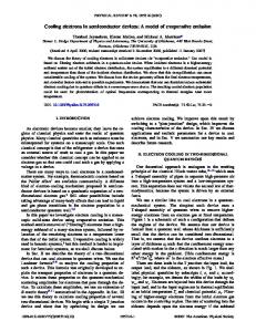
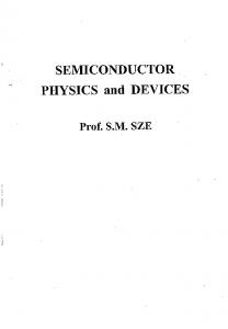
Figure 2. Stopping power (solid triangles) and range (open triangles) of an alpha particle in silicon as a function of its energy. Generated by the software program SRIM [15].
18 16 dQ/dx (fC/um)
14 12 10 8 6 4 2 0 0
5 Alpha Energy (MeV)
10
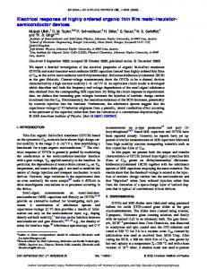
Figure 3. Differential Charge (dQ/dx) curve for an alpha particle in silicon as a function of its energy.
particle is reduced. This non-linear characteristic is one of the reasons knowing the energy spectrum of incident alpha particles is so important to correctly assess device SER. A curve of the stopping power and range of an alpha particle in silicon as a function of its energy is shown in figure 2. Since it is the charge generated by the alpha event that upsets the device, it is convenient for SER calculations to convert the stopping power in terms of differential charge (dQ/dx) as in figure 3. It is important to note that the alpha particle generates anywhere from 4 – 16 fC/µm over its entire energy range. This will be compared with cosmic radiation events which are quite different both in the functionality of the dQ/dx curve and in the magnitude of the charge generated. In the packaged semiconductor product the sources of alpha emitting impurities can be found in the materials used for packaging, the materials used to fabricate the chip, and
in the materials used during the fabrication process. Alpha particle emissions from some key production materials were determined by high sensitivity (large area) alpha counting and are summarized in table 3. The alpha emissivities are reported at the 90% confidence level. Depending on the grade and type of material, a large range of alpha emissivities was observed. Table 3. Alpha emissivities of various materials Material Emissivity (α/cm2-hr) Fully Processed Wafers 30um thick Cu Metal 20um thick AlCu Metal Mold compound Flip Chip Underfill Eutectic Pb-based Solders
< 0.001 < 0.002 < 0.001 < 0.024 – < 0.002 < 0.002 – < 0.001 < 7.200 – < 0.002
In general the primary source of alpha particles is the package materials (mold compound, underfill, solder, etc.) and not the materials used to fabricate the semiconductor device. Assuming one is attempting to minimize a product’s SER by utilizing low alpha emission materials, an emissivity of ~ 0.001 α/hr-cm2 for the packaged part seems to be a limit that can be obtained today. Although some materials/processes may provide lower emission, the alpha counting detection is also limited to ~ 0.001 α/hr-cm2 There are three methods commonly employed to reduce the alpha particle component of SER. The first is to use extremely high purity materials and screen for low alpha emission. Again, the limits of these techniques today is in the 0.001 α/cm2-hr range. Another method commonly employed is to build-in design rules so that packaging components which have the highest alpha emission are kept physically separated from sensitive circuit components. This is frequently used in flip-chip packaging where solder bump placement can be limited by keep-out zones over sensitive circuit components. This technique only works if the package has defined “hot” zones such as solder bumps, and if the chip has circuit elements which are significantly more sensitive that the rest of the chip. The last solution is to shield the high alpha emission materials. This is impossible on flip-chip designs but in lead-frame and ceramic packages shielding is often done with polyimide thin films coated over the finished chip prior to bonding and encapsulation. In the case of “alpha shielding” it is important to know the source and energy of the alpha emissions as using a shield which is not thick enough can actually raise the SER above unshielded units [16] due to the large non-linearity in the alpha particle’s charge generation rate. III.
HIGH ENERGY COSMIC RAYS
The second significant source of SER is related to cosmic ray events. Primary cosmic rays are thought to be of galactic origin and are isotropic. They react with the Earth’s atmosphere via the Strong interaction and produce complex cascades of secondary particles. These in turn
1000
1000
100
Burst Generation Rate
100 10 1
10 1
E=0.1 M eV E=1.0 M eV
0.1
E=5.0 M eV E=10 M eV
0.1 10 100 Neutron Energy(MeV)
0.01
1000
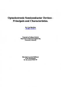
Figure 4. Cosmic ray neutron flux as a function of neutron energy at sea-level. Adapted from Ziegler [17].
continue on deeper into the atmosphere, creating tertiary particle cascades, and so on. At terrestrial altitudes (as opposed to flight or satellite altitudes) less than 1% of the primary flux reaches sea level and the predominant particles include muons, protons, neutrons, and pions. Due to their relatively high flux and stability (pions and muons are short-lived and protons and electrons are attenuated by coulombic interactions with the atmosphere) neutrons are the most likely cosmic radiation to cause an upset in devices at terrestrial altitudes. The cosmic neutron flux at sea level is shown in figure 4. It should be noted that this is an approximate curve built up of many measurements from many different sources. This curve defines how many neutrons over the given energy range are incident on a device at sea level. The neutron flux is strongly dependent on altitude with the intensity of the cosmic ray neutron flux increasing with increasing altitude. For example, in going from sea level to 10,000 feet, the cosmic ray flux increases 10x (this trend starts to saturate at about 50,000 ft.). Hence altitude can have a significant impact on a customer’s perceived SER. Due to proton shielding effects induced by interactions with the Earth’s magnetic field, the neutron flux is also dependent on magnetic rigidity – on geographical location (this effect is less pronounced than the variation due to altitude). A clear and comprehensive assessment of terrestrial cosmic radiation as a function of altitude and location is found in [18]. Since neutrons themselves do not directly generate ionization in silicon, the neutron flux alone does not define the cosmic component of SER. High-energy neutron interactions with silicon and other chip materials are extremely complicated and dependent on the energy of the incident neutron. The primary reaction by which cosmic ray events induce SER is the neutron-induced silicon recoil (both elastic and non-elastic). In this case a neutron collides with a silicon nucleus and transfers enough of its kinetic energy to knock the silicon from the lattice. Typically the silicon nucleus breaks into smaller fragments each of which generate charge. The detailed nature of
E=15 M eV
0
200
400
600
800
1000
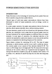
Neutron Energy (MeV) Figure 5. Burst generation rate vs. neutron energy for various silicon recoil energies. Adapted from Letaw [21].
recoil fragments is only now being elucidated by advanced quantum mechanical simulations of the nucleon interactions [19,20]. However, treating the silicon recoil as a single entity yields answers that match with the empirical data, so for the purpose of this discussion we will use this simplifying assumption. Nuclear physics simulations have been used to calculate the distributions in energy of recoils generated as a function of incident neutron energy. Some of the results of these calculations are shown in figure 5 illustrating the charge burst generation rate (in units of cm2/µm3 ) in silicon as a function of different energy recoils. The probability of higher energy recoils increases with increasing neutron energy. More importantly however, the burst generation rate drops rapidly as recoil energy is increases. In fact a 1 MeV recoil is 100-3000 times more likely than a 15 MeV recoil. The true impact to semiconductor devices is the amount of charge an event deposits in the active device volume. The same methodology that was used to generate the 150
8
125 6 dQ/dx (fC/um)
1
100 75
4
50
Range (um)
Neutron Flux (10^6 x n/cm2-s-MeV)
10000
2 25 0
0 0
5 10 Recoil Energy (MeV)
15
Figure 6. Differential charge (solid squares) and range (open squares) of a silicon recoil in silicon vs. energy.
IV. NEUTRON-INDUCED 10B FISSION The third significant source of ionizing particles in electronic devices is the secondary radiation induced from the interaction of cosmic ray neutrons and boron. Boron is used extensively as a p-type dopant and implant species in silicon and is also used in the formation of BPSG (2-8% by weight) dielectric layers. The boron is added to PSG to reduce its reflow temperature from ~ 1100°C to 700-900°C, allowing for improved step coverage and contact reflow at lower processing temperatures. The inclusion of boron in PSG also reduces stress and improves alkali ion gettering. Although chemical mechanical polishing (CMP) has greatly improved planarity, the superior reflow properties of BPSG are still used in many processes. Boron is composed of two isotopes, 11B (80.1% abundance) and 10B (19.9%
Neutron
abundance). The 10B is unstable when exposed to neutrons (the 11B also reacts with neutrons; however, its reaction cross-section is nearly a million times smaller, and its reaction products, gamma rays, are much less damaging). At 3838 barns (1 barn = 1E-24 cm2 per nucleus), the thermal neutron capture cross-section of 10B is extremely high in comparison to most other isotopes - by 3 to 7 orders of magnitude. Unlike most isotopes which emit gamma photons after absorbing a neutron, the 10B nucleus breaks apart, or "fissions", with an accompanying release of energy in the form of an excited 7Li recoil nucleus and an alpha particle (a prompt gamma photon is emitted from the lithium recoil soon after fission occurs). In the 10B(n,α)7Li reaction, illustrated in figure 7, the alpha particle and the lithium nucleus are emitted in opposite directions to conserve momentum. The lithium nucleus is emitted with a kinetic energy of 0.840 MeV 94% of the time and 1.014 MeV 6% of the time. The alpha particle is emitted with an energy of 1.47 MeV. The alpha and the lithium recoil are
100000 Cross-section (barns)
stopping power and range curves for the alpha particles has been applied to silicon recoils and is shown in figure 5. Clearly, the charge density per distance traveled for silicon recoils is significantly higher than that of alpha particles, so cosmic events have a significantly higher potential to upset a semiconductor device as compared to alpha particle events. The charge density for silicon recoils is 25-150 fC/µm while the maximum for alpha particles is 16 fC/ µm. Because they lose their energy more rapidly to the silicon lattice, silicon recoils are rapidly stopped within a few microns for most silicon recoils (< 15 MeV). Unlike alpha particles, the cosmic neutron flux cannot be reduced significantly at the chip level with shields, keepout zones, or high purity materials. Concrete has been shown to shield the cosmic radiation at a rate of approximately 1.4x per foot [16] of concrete thickness. Thus the SER due to cosmic neutrons of a system operating in a basement surrounded by many feet of concrete could be significantly reduced. While this may be a viable option for mainframes, for personal desktop applications or portable electronics little can be done to reduce the cosmic ray portion of the SER. Cosmic ray SER must therefore be dealt with by reducing device sensitivity, either by design or process modifications – these improvements will be discussed in part II of the series.
10000 1000 100 10 0.001 0.01 0.1 1 10 Neutron Energy (eV)
100
Figure 8. Neutron capture cross-sections for 10B as a function of neutron energy. Note the rapid (~1/E) drop in cross-section as neutron energy increases. 7Li
Recoil
γ - photon
10B
a.)
Nucleus
α - particle
b.)
Figure 7. Schematic of the process of 10B fission. Neutron capture occurs a.) at a relatively high rate due to 10B’s high neutron capture cross section. The unstable nucleus fissions b.) producing ionizing recoil fragments.
Cumulative Probability
1.0 0.8 0.6 0.4 0.2 0.0 0
0
0.01 0.1 1 10 Neutron Energy (eV)
100
Figure 9. Cumulative probability function based on 10B crosssection and cosmic neutron background flux vs. neutron energy.
both capable of inducing soft errors in electronic devices. The 10B is easily "activated" by the ever-present cosmic ray neutron flux. Referring to figure 8, it is clear that neutrons of any energy can induce the reaction, but since the 10B capture cross-section decreases rapidly as neutron energy is increased, only neutrons in the epi-thermal energy range need be considered. A calculation based on convolving the cross-section curve with the cosmic background neutron flux shows that 90% of the reactions are caused by neutrons with energies below 15 eV (figure 9). It is important to note that the low energy neutron cosmic background flux is not well defined – since lower energies are more easily scattered, the local environment can induce large flux differences from location to location. Assuming maximum doping and implant levels
V. CONCLUSION
25 20 dQ/dx (fC/um)
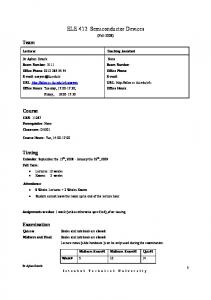
encountered in standard processes and a BPSG layer containing 5% boron, the 10B concentration in diffusions and implants (which are predominantly 11B) is thousands of times lower than that of the BPSG layer. The range of the alpha particle and lithium recoil is < 3 µm, and calculations have shown that in most cases beyond ~ 0.5µm they have insufficient energy to induce soft errors. Thus only BPSG in close proximity to the silicon substrate should be considered a threat. For conventional BPSG-based semiconductor processes, the BPSG is the dominant source of boron fission and in some cases can be the primary cause of soft errors [9,10]. Besides alpha particles, whose interaction with matter was covered in the first section, the 10B(n,α)7Li reaction results in the emission of an energetic lithium recoil. Figure 10 illustrates the differential charge generation as a function of energy for the Lithium recoil and an alpha particle. The lithium recoil with a kinetic energy of 0.840 MeV generates charge at 25 fC/µm while the 1.47 MeV alpha particle generates a maximum of 16 fC/ µm. The alpha and the lithium recoil are both capable of inducing soft errors in electronic devices. Clearly the lithium generates more charge along its path length and thus has a higher probability of generating a soft error. The SER due to the activation of 10B in BPSG can be mitigated in several ways. The first and most direct is simply to eliminate BPSG from the process flow. Due to the limited range of the alpha and lithium recoil emitted during the 10B(n,α)7Li reaction, only the first level of BPSG need be replaced with a dielectric free of 10B. In cases where the unique reflow and gettering properties of boron are needed the regular BPSG process can be replaced by an enriched 11BPSG process without changing the physical or chemical properties of the film and without the requirement for new equipment or processing steps.
15 10 5 0 0
5 Particle Energy (MeV)
10
Figure 10. Differential Charge (dQ/dx) curve for the lithium recoil (solid triangles) in silicon as a function of its energy. The same curve for an alpha particle is also shown for reference (open squares).
Package-level radiation in semiconductor devices is the sum of three independent mechanisms; alpha particles emitted from the radioactive impurities in the device materials, terrestrial cosmic radiation in the form of highenergy neutrons, and 10B fission events induced by the low energy neutrons from the cosmic background. To accurately determine the SER of any product, the SER for each of the three components must be accounted for. In this paper we have had an in-depth look at the way in which each of these ionizing radiations induces charge in silicon and we have discussed methods to reduce the impact or contribution of the sources of each radiation. In the next installment we shall consider the dynamics of charge collection for the three radiation components, and how each type of event causes soft errors in SRAM, DRAM, and logic circuits. Design and process technology methodologies to reduce SER will also be considered.
REFERENCES [1] [2] [3] [4]
[5] [6] [7] [8] [9] [10] [11]
[12] [13] [14] [15] [16] [17] [18] [19]
[20]
[21]
T. C. May and M. H. Woods, "Alpha-Particle-Induced Soft Errors in Dynamic Memories," IEEE Trans. on Elec. Devs., vol. 26, no. 1, p. 2-8, 1979. C. M. Hsieh, P. C. Murley, and R. R. O'Brien, "Dynamics of Charge Collection from Alpha-Particle Tracks in Integrated Circuits," Proc. IRPS, p. 38-42, 1981. J. F. Ziegler and W. A. Lanford, "The Effect of Sea Level Cosmic Rays on Electronic Devices," J. Appl. Phys., vol. 52, p. 4305-4318, 1981. C.A. Gossett, B.W. Hughlock, M. Katoozi, G.S. LaRue, and S.A. Wender, "Single Event Phenomena in Atmospheric Neutron Environments," IEEE Trans. Nuc. Sci., vol. 40, no. 6, p. 1845-1856, 1993. G.R. Srinivason, P.C. Murley, and H.K. Tang, "Accurate, Predictive Modeling of Soft Error Rate Due to Cosmic Rays and Chip Alpha Radiation," IEEE Proc. IRPS, p. 12-16, 1994. E. Normand. “Single Event Upset at Ground Level,” IEEE Trans. Nucl. Sci., vol. 43, no. 6, p. 2742-2750, 1996. T. R. Oldham, S. Murrill, and C.T. Self, “Single Event Upset of VLSI Memory Circuits Induced by Thermal Neutrons,” Radiation Effects, Research, and Engineering, vol. 5, no. 1, p. 4-12, 1986. R. C. Baumann, T. Z. Hossain, S. Murata, H. Kitagawa, "Boron Compounds as a Dominant Source of Alpha Particles in Semiconductor Devices," IEEE Proc. IRPS, p. 297-302, 1995. R. C. Baumann, T. Z. Hossain, E. B. Smith, S. Murata, H. Kitagawa, "Boron as a Primary Source of Radiation in High Density DRAMs," IEEE Proc. VLSI Symp., p. 81-82, 1995. R. C. Baumann and E. B. Smith, "Neutron-Induced Boron Fission as a Major Source of Soft Errors in Deep Submicron SRAM Devices," IEEE Proc. IRPS, p. 152-157, 2000. R. C. Baumann and E. B. Smith, "Neutron-induced 10B fission as a major source of soft errors in high density SRAMs,” to be published in Elsevier Microelectronics Reliability, vol. 41, no. 2, p.211-218, 2001. R. C. Baumann and J. W. McPherson, “Impact of Alpha-Particle Emitting Impurities in Phosphoric Acid on the Soft Error Rate of DRAMs.” Texas Instruments Tech. Report, Nov. 1991. Z. Hasnain and A. Ditali, "Building-in Reliability: Soft errors – A Case Study," IEEE Proc. IRPS Symp., pp. 276-280, 1992. Low-Alpha Lead Symp., Lawrence Livermore National Laboratories, Feb. 1997. SRIM ”Stopping and Range of Ions in Matter” software (version 2000.05) by J. F. Ziegler and J.P. Biersack. R. C. Baumann, “Investigation of the Effectiveness of Polyimide Films for the Stopping of Alpha Particles in Megabit Memory Devices” Texas Instruments Tech. Report, April 1991. J. F. Ziegler, "Terrestrial cosmic rays," IBM J. Res. Develop., Vol. 40, No. 1, p. 19-39, 1996. J. F. Ziegler, "Terrestrial cosmic ray intensities," IBM J. Res. Develop., Vol. 42, No. 1, pp. 117-139, 1998. A. Ono, H. Horiuchi, T. Maruyama, and A. Ohnishi, "Fragment Formation Studied with Antisymmetrized Version of Molecular Dynamics with Two-Nucleon Collisions”, Phys. Rev. Lett., vol. 68, p. 2989-2994, 1992. Y. Tosaka, H. Kanata, T. Itakura, and S. Satoh, "Simulation Technologies for Cosmic Ray Neutron-Induced Soft Errors: Models and Simulation Systems”, IEEE Trans. Nucl. Sci., vol. 46, No. 3, p. 774-779, 1999. J.R Letaw and E. Normand, "Guidelines for predicting singleevent upsets in neutron environments (RAM devices)”, IEEE Trans. Nucl. Sci., vol. 38, p. 1500-1506, 1991.