Space Compaction and Use of Minimal Logic Gate in VLSI Test Circuit Design by Uniquely Developed Algorithm Based on Graph Theoretical Approach Md. Fairuz Siddiquee; Md. Mahmudul Hasan Department of Electrical & Electronic Engineering, Ahsanullah University of Science & Technology, Dhaka-1208, Bangladesh
[email protected];
[email protected] Abstract— The design and implementation of space-efficient hardware for built-in self-testing circuit is very important step for synthesizing very large scale integration circuits. This research presents a new technique for merging output test vectors. The proposed technique takes advantage of some wellknown concepts of conventional switching theory, together with the selection of specific gates for merger of an arbitrary but optimal number of output bit streams from the circuit under test. This is a new technique as it is implemented without any modification of the original circuit. But the maximum compaction is achieved in almost all cases within a reasonable time span. The proposed technique is illustrated with design details of space compactors for ISCAS (International Symposium on Circuits and Systems) 85 combinational benchmark circuits using simulation programs ATALANTA. The simulation result confirms the usefulness of the approach for its simplicity, resulting low area overhead, and full fault coverage for single stuck-line faults, thereby making it suitable in a VLSI design environment. Keywords—BIST; Space Compaction; ATE; Bron-Kerbosch Algorithm; Graph Theory; Clique; DUT; Fault Simulation and coverage
I. INTRODUCTION Design for Test (also known as "Design for Testability" or "DFT") is a name for design techniques that add certain testability features to a microelectronic hardware product design. The purpose of manufacturing tests is to validate that the product hardware contains no defects that could, otherwise, adversely affect the product’s correct functioning. Tests are applied at several steps in the hardware manufacturing flow and, for certain products, may also be used for hardware maintenance in the customer’s environment. The tests generally are driven by test programs that execute in Automatic Test Equipment (ATE) or, in the case of system maintenance, inside the assembled system itself. In addition to finding and indicating the presence of defects (i.e., the test fails), tests may be able to log diagnostic information about the nature of the encountered test fails[1-5]. The diagnostic information can be used to locate the source of the failure.
In other words, the response of vectors (patterns) from a good circuit is compared with the response of vectors (using same patterns) from a DUT (device under test). If the response is the same or matches, the circuit is good. Otherwise, the circuit is faulty. DFT plays an important role in the development of test programs and as an interface for test application and diagnostics. Automatic test pattern generation, or ATPG, is much easier if appropriate DFT rules and suggestions have been implemented. Automatic or Automated Test Equipment (ATE) is any apparatus that performs tests on a device, known as the Device Under Test (DUT) or Unit Under Test (UUT), using automation to quickly perform measurements and evaluate the test results. An ATE can be a simple computer controlled digital multi-meter, or a complicated system containing dozens of complex test instruments (real or simulated electronic test equipment) capable of automatically testing and diagnosing faults in sophisticated electronic packaged parts or on Wafer testing, including System-On-Chips and Integrated circuits. Space compaction of test response provides parallel access to functional output and reduces testing time and test data volume. The realization of space-efficient support hardware for built-in self-testing (BIST) is of great significance in VLSI circuits design. Testing in its broadest sense means to examine a production and to ensure that it functions and exhibits the properties and capabilities that it was designed to possess[4-7]. Main purpose of testing is to detect malfunctions in the product hardware and to locate their causes so that they may be eliminated. A built-in self-test (BIST) or built-in test (BIT) is a mechanism that permits a machine to test itself. Engineers design BISTs to meet requirements such as: 1. High reliability 2. Lower repair cycle times Constraints are: 1. Limited technician accessibility 2. Cost of testing during manufacture The main purpose of BIST is to reduce the complexity, and thereby decrease the cost and reduce reliance
upon external (pattern-programmed) test equipment. BIST reduces cost in two ways: 1. Reduces test-cycle duration 2. Reduces the complexity of the test/probe setup, by reducing the number of I/O signals that must be driven /examined under tester control. Both lead to a reduction in hourly charges for automated test equipment (ATE) service[7-10]. Space compaction of test response provides parallel access to functional output and reduces testing time and test data volume. The realization of space-efficient support hardware for built-in self-testing (BIST) is of great significance in VLSI circuits design. II. IMPORTANCE OF TESTING Let, ‘N’ is the number of transistors in a chip and ‘p’ is the probability of that a transistor is faulty & ‘Pf’ is the probability that the chip is faulty. Then, Pf = 1- (1- p) N p = 10-6
If
N = 106
Maximal Clique: A Clique that cannot be extended by including one more adjacent vertex. In the 1990s, a breakthrough series of papers beginning with Feige (1991) and reported at the time in major newspapers, showed that it is not even possible to approximate the problem accurately and efficiently.
III. BRON-KERBOSCH ALGORITHM The Algorithm was designed and Published in 1973 by the Dutch scientists Joep Kerbosch and Coenradd Bron. Bron-Kerbosch Algorithm is for finding the Maximal Cliques in undirected graph. It is known to be one of the most efficient algorithms which uses recursive backtracking to find Cliques is practically proven. The Bron-Kerbosch Algorithm uses the vertex in graph and its neighbors with few functions to generate some effective results.
Then, Pf = 63.2% A.
Fault Coverage
FC = No faults detected /No faults in fault list Let a AND gate has two inputs: a, b and one output: c So, possible 6 stuck-at faults: (a0, a1, b0, b1, c0, c1) Test
faults detected
FC
R=X=Φ, P = (1, 2, 3, 4, 5, 6)
{(0,0)}
c1
16.67%
Choosing the pivot element as 4.
{(0,1)}
a1,c1
33.33%
{(1,1)}
a0,b0,c0
50.00%
4 in P \ N (v) = (1, 2, 3, 4, 5, 6) \ (1, 2, 3, 5, 6) = 4 in 4 Find’s the values of Pnew, Rnew ,Snew
{(0,0),(1,1)}
a0,b0,c0,c1
66.67%
Pnew = P ∩ N (v), Rnew = R ∪ (v), Xnew = X ∩ N (v)
{(1,0),(0,1),(1,1)
all
100.00%
Rnew = 4, Pnew = (1, 2, 3, 5, 6), Xnew = Φ Bronkerbosch(4),(1,2,3,5,6),Φ)
B.
Clique Bronkerbosch((4,1),(2,3),Φ)
The ‘Clique’ terminology comes from Luce and Perry (1949). First Algorithm for solving the Clique problem is that of Harary and Ross (1957). Tarjan and Trojanowski (1977), an early work on the worst-case complexity of the Maximum Clique problem. Maximum Clique: A Clique of the largest possible size in a given graph.
Bronkerbosch((4,1,2),Φ,Φ) Report (4, 1, 2) as one of the Maximal Clique Bronkerbosch((4),(1,2,3,5,6),Φ) Bronkerbosch((4,3),(1), Φ) Bronkerbosch((4,3,1),Φ,Φ) Report (4, 3, 1) as one of the other Maximal Clique
Bronkerbosch((4),(1,2,3,5,6),Φ) Bronkerbosch((4,2),(1,5),Φ) Bronkerbosch((4,2,5),Φ,Φ)
Step 16) Inject stuck-at logic faults into the newly generated circuit under test (original circuit under test + compactor hardware).
Report (4, 2, 5) as another Maximal Clique Bronkerbosch((4),(1,2,3,5,6), Φ) Bronkerbosch((4,6), Φ, Φ) Report (4, 6) as the Maximal Clique IV.
ALGORITHM 1
Step 1) Define the possible maximum number of stages in the space compaction trees at the circuit under test output. Step 2) Compute the total number of output lines in the circuit under test. Continue the following steps unless there is only a single output line (possibly).
Step 17) Compute fault coverage by applying input test patterns. Step 18) If the fault coverage is 100%, then replace the old circuit under test with the new circuit under test, and repeat step 2 for computing the second stage of the compactor. Step 19) If the fault coverage is less than 100%, then merge all the remaining lines with two-input XOR two output lines at a time. Step 20) Add a new output line corresponding to the selected merged outputs.
Step 3) Find the sets of all maximal compatible classes from the circuit under test for logic AND, OR, and XOR by employing Algorithm B (mentioned later).
Step 21) Inject stuck-at logic faults into the newly generated circuit under test (original circuit under test + compactor hardware).
Step 4) Select a maximal compatible class MCi based on largest number of output lines, from the sets of all maximal classes. Select the second largest class during subsequent iteration, if 100% fault coverage is not realized in the preceding iteration from the same circuit under test. Step 5) Merge the selected output lines of the MCi using appropriate logic gates AND, OR, or XOR.
Step 22) Compute fault coverage by applying input test patterns.
Step 6) Add a new output line corresponding to the selected merged outputs in MCi. Step 7) Discard all the output lines already used in MCi.
Step 23) If the fault coverage is less than 100%, then continue to work on the same circuit under test and repeat step 4 for selecting a new maximal compatible class MCk. Step 24) If the fault coverage is 100%, then replace the old circuit under test with the new circuit under test, and repeat step 2 for computing the second stage and subsequent stages of the compactor. V. ALGORITHM 2
Step 8) Search for another MC class MCj from the remaining output lines. Step 9) Merge the selected output lines in MCj using appropriate logic gates. Step 10) Add a new output line corresponding to the selected merged outputs in MCj. Step 11) Discard all the output lines already used in MCj. Step 12) Repeat step 8 as long as there are maximal classes in the sets, and enough output lines. Step 13) Calculate all the remaining output lines that do not belong to any of the selected maximal classes. Step 14) Merge all the remaining lines with XOR gate. Step 15) Add a new output line corresponding to the selected merged outputs.
This algorithm implements the well-known Bron-Kerbosch algorithm for maximal clique finding. Steps are mentioned below: Step 1) Calculate the total number of vertices in the undirected graph. Step 2) Find the connected diagonal elements of the graph. Step 3) Select a candidate point. Step 4) Merge the selected candidate to a set called compsub, which is to be extended by a new point, or shrunk by a point on traveling along a branch of the backtracking tree. Step 5) Generate a new set called candidates, which is the set of all points that will in due time serve as an extension to the present configuration of compsub. Step 6) Create another set called not, which is the set of all points that, at an earlier stage, already served as an extension
of the present configuration of compsub, and are now explicitly excluded.
VII. A.
FAULT SIMULATION AND RESULTS
ISCAS Combinational Benchmark Circuit C432
Step 7) Remove all points not connected to the selected candidate, keeping the old sets intact. Step 8) Call the extension operator to perform on the newly generated sets. Step 9) Remove the selected candidate from the compsub, and add it to the old set not after returning. VI.
ALGORITHM 3
Algorithm 3 is the algorithm to compute and generate all the compatible pairs of the circuit under test for logic gates AND, OR, XOR. Step 1) Calculate the total number of output lines of the circuit under test. Step 2) Generate all possible combinations (Ai, Aj) of output lines, taken two at a time, and store all pairs of the output lines (Ai, Aj).
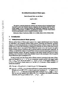
Fig 1: Circuit of C432
Step 3) Select the first pair from the list of combined output lines (Ai, Aj). Step 4) Merge the selected pair of output lines (Ai, Aj) using logic gates AND, OR, and XOR respectively, using only one logic gate at a time. Step 5) Add a new output line to the original circuit under test corresponding to the outputs (Ai, Aj), one at a time. Step 6) Discard the output lines (Ai, Aj) from the original circuit under test, and generate a new modified circuit. Step 7) Inject stuck-at logic faults into the newly generated circuit and apply test patterns.
Fig 2: Compactor Circuit 1 for C432
Step 8) If the fault coverage is equal to 100%, then store the output pair (Ai, Aj) in the compatible pairs database of logic AND, OR, and XOR respectively. Step 9) Delete the pair just selected, from the list of combined output lines (Ai, Aj) and select the next pair. Step 10) Repeat step 4 and continue until all pairs are selected.
Fig 3: Compactor circuit 2 for c432
Fault simulation result in ATALANTA without compaction:
B.
ISCAS Combinational Benchmark Circuit C3540
Fig 4: Circuit of C3540
Fault simulation result in ATALANTA with compaction:
Fig 5: Compactor Circuit 1 for C3540
Fig 6: Compactor Circuit 2 for C3540
Fault simulation result in ATALANTA without compaction:
Fault simulation result in ATALANTA with compactor-circuit 1:
Fault simulation result in ATALANTA with compactorcircuit 2:
VIII. CONCLUSION This paper presents a new technique for solving space compaction problem of circuit under test (CUT). The technique utilizes conventional switching theory concepts. In the selection of specific gates for merger of an arbitrary but optimal number of output bit streams from the CUT. This is an efficient technique and it is achieved without any prior modification of the original circuit (MUT), as all the modification for testing is done in software mode, whereas maximal compaction is realized in most cases in reasonable time utilizing some simple heuristics. The technique, illustrated with details of design of space compactors for ISCAS 85 combinational with ATALANTA simulation programs, confirms the usefulness of the suggested approach, its simplicity, resulting low area overhead, and full fault coverage (FC) for single stuck-line faults, making it suitable in a VLSI design environment as BIST support hardware. It might be fair to mention here that the test vectors used for detecting single stuck-line faults in digital BIST these days, irrespective of whether the circuits are combinational or fullscan sequential, are either deterministic, minimal or nonminimal, complete, or simply reduced but not necessarily complete, or pseudorandom. If minimal complete test sets are available for ISCAS 85 circuits, this is obviously would be the best choice in testing any circuit for complete FC using minimal time and resources. On the other hand, programs such as ATALANTA as used in the paper generate reduced test sets that detect most single
stuck-line faults for ISCAS 85 circuits, which give very good fault coverage, not necessarily 100%, for most of the ISCAS benchmark circuits. All these types of test vectors are absolutely compatible with the approach developed in this research. Notwithstanding this, the proposed theoretical framework, although was simulated on the assumption of single stuck-line faults, is amenable to modification to take care of multiple fault situations as well, if programs are available to simulate multiple stuck line faults. But, multiple faults are extremely difficult to analyze in view of their sheer number. Besides, modern day circuits are extremely reliable not to exhibit simultaneous multiple stuck-line faults, although there are occasions where these faults need to be considered. However, in this work, we did not, as in the case of most other studies. Besides, we do not consider faults such as stuck-open faults, short faults, bridging faults, intermittent faults or transient faults in our analysis, the last two types being very difficult to investigate theoretically, requiring discrete or continuous Markov modeling. With advances in computational resources, evidently this heuristic space compaction algorithm might be improved upon for better efficiency in respect of time and storage. IX.
ACKNOWLEDGEMENT
We would like to express our sincere gratitude to Dr. Satyen Biswas (Ph.D., P.E), Professor, Department of Electrical and Electronic Engineering, Ahsanullah University of Science and Technology, Dhaka, Bangladesh for the continuous support of our study and research, for his patient guidance, enthusiastic encouragement and useful critiques of this research work. His friendly supervising supported us a lot. X. REFERENCES 1. 2.
3. 4.
5.
E. J. McCluskey, “Built-in self-test techniques”, IEEE Design & Test of Computers, 2, 1985, pp. 21-28. R. G. Daniels and W. B. Bruce, “Built-in self-test trends in Motorola microprocessors”, IEEE Design & Test of Computers, 2, 1985, pp. 6471. S. R. Das, “Built-in self-testing of VLSI circuits”, IEEE Potentials, 10, 1991, pp. 23-26. Satyendra Biswas, Sunil R. Das, Emil M. Petriu; Space Compactor Design in VLSI Circuits Based on Graph Theoretic Concepts; IEEE TRANSACTIONS ON INSTRUMENTATION AND MEASUREMENT, VOL. 55, NO. 4, AUGUST 2006. Das, S.R. , Hossain, A. , Biswas, S. , Petriu, E.M.; Aliasing-free compaction revisited; Circuits, Devices & Systems, IET (Volume:2 , Issue: 1 )Page(s):166 – 178;February 2008.
6.
Das, S.R. , Hossain, A. , Biswas, S. , Petriu, E.M.; Aliasing-free compaction revisited; Circuits, Devices & Systems, IET (Volume:2 , Issue: 1 )Page(s):166 – 178;February 2008.
7.
Biswas, S.N.; Das, S.R. ; Petriu, E.M. ; Hossain, A.; Hybrid test vector compression in system-on-chip test — An overview and methodology; Computers and Devices for Communication, 2009. CODEC 2009. 4th International Conference on; Page(s):1 – 6; 14-16 Dec. 2009.
8.
Biswas, S.; Das, S.R.; Hossain, A.; VLSI Circuit Test Vector Compression Technique; Instrumentation and Measurement Technology Conference Proceedings, 2007. IMTC 2007. IEEE; Page(s):1 – 6; 1-3 May 2007.
9.
Neil H. E. Weste; David Harris; Ayan Banrejee; CMOS VLSI Design: A Circuit and System Perspective; Third Edition; Page(s):531-570.
10. Hossain, A.; Groza, V.; Das, S.R.; Aliasing-Free Space Compaction in VLSI with Cascade of Two-Input OR/NOR Logic; Electronic Design, Test and Application (DELTA), 2011 Sixth IEEE International Symposium.