The SPARC project [1] consists in a 150MeV Linac aimed at driving an ondulator for the production of 530nm. SASE FEL radiation. A bunch transverse ...
Proceedings of 2005 Particle Accelerator Conference, Knoxville, Tennessee
THE SPARC RF SYNCHRONIZATION SYSTEM Alessandro Gallo, David Alesini, Marco Bellaveglia, Roberto Boni, Giampiero Di Pirro, Franco Tazzioli (INFN/LNF, Frascati (Roma)) Abstract
K2
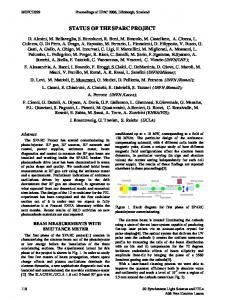
RF SYSTEM BASIC ARCHITECTURE Precise synchronization among the RF accelerating voltages (SW in the RF Gun and TW in the 3 S-band SLACtype sections), and between these voltages and the laser pulse on the gun photocathode is very important to reach the SPARC design emittance goal in a stable, routine operation. In SPARC phase II, where the RF compression of the bunch will be tested, the laser pulse needs to be locked to the RF voltages within σt = 0.5psrms . The accelerating voltages need to be kept synchronized each other within an even lower figure. The basic RF layout including the amplitude and phase control architecture is shown in Fig. 1. The RF power will be generated by two 45M W , 4.5µs pulsed klystrons. One klystron powers the RF gun, the 3rd accelerating section and the RF deflector, while the other is connected through a SLED pulse compression system to the 1st and 2nd accelerating sections. By playing with the klystron low-level RF and with some waveguide attenuators/phase shifters placed in the various branches, it is possible to individually control the level and the phase of all the RF accelerating voltages. In order to do that, the amplitudes and phases of RF voltage samples have to be measured and recorded at each pulse, and feedback algorithms have to be implemented to correct pulse-to-pulse drifts. About 20 pulsed RF signals, with various pulse envelope profiles, have to be demodulated to monitor their phase and amplitude. In fact, the pulses produced by the klystrons as those entering and leaving the section S3 are almost flat in the 4.5ps duration, while those related to the SW cavities (the RF gun and the RF deflector) and those produced by the SLED system present a relevant internal structure. The way we are proposing to handle these different kinds
c 0-7803-8859-3/05/$20.00 2005 IEEE
BPSK
KLYSTRON Tunnel LINAC Hall
to Laser synchr.
REFCirc
T
Computer Data Processing and Slow Control
T
REFGun FWDGun PbGun
Gun
RFBM
REFS1 FWDS1
S1
FWDL1
REFL1
REFS2 FWDS2
S2
FWDL2 REF L2
Demodulation Board
Digitizer
FWDCirc
The SPARC project [1] consists in a 150M eV Linac aimed at driving an ondulator for the production of 530nm SASE FEL radiation. A bunch transverse emittance as low as 1mm mrad and a bunch peak current of about 100A are required for this task. The RF voltages in the RF gun and in the 3 S-band accelerating sections have to be kept phase locked within 3ps to the arrival time of the laser pulse on the photocathode to guarantee the required performances. This specification will be reduced to 0.5ps in the phase II of the project when the rectilinear RF compression of the bunch will be tested. The general architecture of the SPARC RF control system together with some bench qualification measurements of the basic components is presented in this paper.
D1
K1
D2
2856 MHz 20 W Master oscillator
REFS3 FWDS3
FWDL2
REFL2
S3
REFDefl PbDefl
FWDDefl
Defl
Figure 1: SPARC RF system layout of RF pulses is to use linear I&Q demodulators followed by digitizer boards integrated in an industrial PC, as shown in Fig. 2. The LO reference signals provided to the demodulators are just amplified copies of the master oscillator. To avoid individual jitter of the various LO signals, the master oscillator is amplified just once to a medium-power level (� 20W CW ) and then passively split into many copies each taken as reference for one demodulation channel. By doing that the low-level RF control is virtually completely passive, and the only expected phase jitter related to RF amplification is that coming from the klystrons and their driving stages. The phase lock between the laser pulse and the RF reference is one the most delicate synchronization item. The laser shot synchronization to the master RF reference will be monitored and pulse to pulse drifts will be automatically corrected.
1024
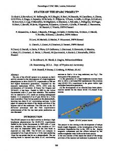
Figure 2: Demodulation channel
Proceedings of 2005 Particle Accelerator Conference, Knoxville, Tennessee
PULSED RF SIGNAL DEMODULATION The amplitude and phase of each pulsed RF signal in SPARC are detected by a demodulation channel sketched in Fig. 2. The I&Q demodulator is a custom device provided by Pulsar µ-wave inc. (I4 0428TM model) under our specifications. The internal mixers are rated for a LO level as large as +27dBm CW , so that RF signals up to +19 dBm level can be linearly demodulated. The SPARC RF signals will be directly mixed down to baseband generating I&Q signals up to the level of 1V (� +10dBm). The I&Q signals are then sampled at a 20M s/s rate and 12-bit digitalized by means of a the ADLINK PCI 9812TM board. Each pulse, which is about 4.5µs long, is converted into 90 I&Q samples. These data are numerically converted in amplitude and phase of the RF in the pulse by applying some simple algebra. A typical measured phase detection characteristics from I&Q signals obtained with a Pulsar I4 0428TM powered at LO = +27dBm and RF = +16dBm is shown in Fig. 3.
obtained with a 10-bits digitizer board (instead of the 12bits one foreseen for this task) and at a +10dBm RF pulse level, a value that does not fully benefits the I&Q mixer dynamic range.
LASER-RF SYSTEM SYNCHRONIZATION The stability of the synchronization between the laser pulse and the RF reference is crucial task. The laser system will be synchro-locked to a RF/36 signal (79.33M Hz) generated in the SPARC timing system. The time jitter of the final UV laser shot respect to the RF synchro-lock has been specified by the laser system manufacturer to be σtlaser ≤ 500f srms .
Figure 5: Laser pulse synchronization monitoring
Figure 3: I&Q voltages and phase detection curve The phase resolution of the demodulation channel has been measured on the bench. The phase of an RF pulse having the SPARC time structure (4.5µs duration, 10Hz rep. rate) has been acquired and recorded for a large number ( 104 ) pulses. The phase value associated to each pulse has been obtained by averaging over the 90 I&Q samples contained in the pulse. A typical statistical distribution of the record is reported in the histogram of Fig. 4.
Figure 4: Pulse-to-pulse phase measurement distribution The standard deviation of the displayed record is σphase = 0.046◦ @ f = 2856M Hz, which corresponds to a measured temporal resolution of � 45f s. This value already meets the SPARC synchronization system requirements, and it may be further improved since it has been
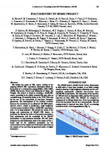
Pulse-to-pulse phase drifts of the laser-to-RF lock have to measured and corrected by a dedicated feedback algorithm. In order to measure the stability of the synchronism between the laser shot and the RF reference line, we are proposing the scheme reported in Fig. 5. The laser shot is converted in a long lasting RF exponential pulse generated by a RF cavity tuned at 2856M Hz excited with a short pulse from a fast photodiode illuminated with a sample of the laser pulse. The RF phase of the exponentially decaying pulse with respect to the RF reference signal is measured again by means of an I&Q mixer. The same phase measurement will be performed on the bunch released by the RF gun. In this case the exponential pulse will be produced by a 2856M Hz ”bunch monitor” cavity placed between the RF gun and the accelerating section S1 excited directly by the bunch. This approach to the phase measurement of pulses whose duration is much shorter than the RF period has been tested on the bench. The measurement layout is sketched in Fig. 6. Short pulses are obtained by exciting a step recovery diode at the 28th sub-harmonics (102M Hz) of the linac RF frequency. The repetition rate of the pulses is reduced from 102M Hz to 100kHz by gating the pulse train through a fast RF switch. The pulse train emerging from the RF switch is filtered by a 2856M Hz cavity that convert it in a series of a RF pulses with exponential profiles and decay time of about 500ns each. The exponential pulses are amplified and demodulated with an I&Q mixer driven with a LO reference signal obtained extracting the 28th harmonics from the original 102M Hz pulse train by means of a PLL circuit.
1025
c 0-7803-8859-3/05/$20.00 2005 IEEE
Proceedings of 2005 Particle Accelerator Conference, Knoxville, Tennessee 2856 MHz pill-box cavity 102 MHz Oscillator
Tektronix stimoulus system
Stanford pulse controller
BHP-200 MCL high-pass
Herotek step recovery diode
RF Amp
RF Amp
INDUSTRIAL PC Fast RF switch Trigger
ADLINK PCI 9810 20 Ms/s, 10 bit Sampling Board I Q
RF Amp
3 dB splitter
0
90
I
SOFTWARE Q f
Amp
0
0 3 dB splitter
PULSAR ID I4 0428 I&Q demodulator
RF Amp
RF Amp
LO +27 dBm RF Amp
VCO
PLL @ 2856 MHz
Figure 6: Short pulse synchronization bench measurement The spectral content at 2856M Hz of the 100kHz short pulses train is quite low, so it is necessary to put many RF amplification stages along the path to the demodulator input to restore a suitable level of the signal. This should not be necessary in the final layout of Fig. 5 since higher levels of the signals to be monitored are expected. Typical I&Q signals acquired for a single short pulse with this setup and the extrapolated amplitude and phase are reported in Fig. 7. A statistical distribution of the pulse phase values over a record of 105 pulses is reported in Fig. 8. The measured standard deviation of the distribution is 0.63◦ . The resolution obtained with this set-up is reasonably good and we believe that it may be improved in the final setup where less RF amplification will be needed and 14-bit, 65M s/s sampling boards (ADLINK PCI 9820TM ) will be used. Other methods for measuring the synchronization stability of short pulses based on triggered oscillators phase measurement are presently under study by the Sincrotrone Trieste group [2].
means of dedicated feedback loops. However, as a consequence of the Nyquist theorem and being the pulse repetition rate of the linac 10Hz, the phase noise in the system can only be corrected in a frequency band below 5Hz. Only thermal drifts are within this band, while noise generated by mechanical vibrations (microphonic noise), power supply ripple and electronic interferences can not be corrected in this way and have to be limited as much as possible at the system design stage. Concerning the phase noise introduced by the RF power stations we are studying the possibility of implementing an intra-pulse phase lock feedback around them. Being the station group delay of the order of 150ns (mainly due to the klystron frequency response) a feedback loop with 1M Hz bandwidth, capable to get to regime in 1µs, is in principle doable. In this way the noise introduced by the RF power stations could be corrected inside each pulse and in a wide bandwidth. A model of this system has been tested on the bench, easily reaching the expected performances. The system will be tested on the SPARC RF power stations after their installation before the end of this year.
Figure 8: Distribution of short-pulse phase measurements
CONCLUSIONS
Figure 7: Typical I&Q signals acquired for a single short pulse (a, b) and extrapolated amplitude (c) and phase (d)
REFERENCES [1] M. Ferrario et al., “Status of the SPARC project”, EPAC 2004 Proceedings, Lucern (Switzerland), pag. 399, ISBN: 92-9083-231-2
FEEDBACK SYSTEMS The information on the RF phase of each monitored signal will be used to correct the measured deviations by
c 0-7803-8859-3/05/$20.00 2005 IEEE
The quality of the SPARC RF control is crucial to reach the goal of the project in terms of low emittance and high brillance of the bunch. The system has been completely designed and is going to be assembled since all the needed components have been acquired. The resolution of the demodulation channel has been measured on the bench and it is � 50f s. A possible layout for measuring the stability of the synchronization of short pulses respect to the reference RF has been bench tested with a measured resolution of � 600f s. The system hardware will be improved to reach a finer resolution. The whole SPARC RF low level control system will be completed and installed by the end of this year.
[2] M. Ferianis, private communication
1026