Sparse Representation Based Range-Doppler Processing for ...
Recommend Documents
above methods, widening the dataset that these methods can successfully ..... Sign Recognition Benchmark (GTSRB)4 Challenge is held at IJCNN 2011 [20].Missing:
{'ZNF217'}, {'RB1'}, {'TP53'}, {'BCAS1'}. To locate those genes, more genes should be selected or other gene shaving criteria should be applied. In addition to that ...
The sparse representation based classifier (SRC) and its kernel version (KSRC) have been employed for .... is the training dictionary in kernel-induced feature.
for robust automatic speech recognition (ASR), most of them relying on the ..... Figure 4: Forming an atom template for a single phonetic state. Training data ...
GMM-based conversion with global variance (GV) enhancement, our method achieved ... Voice conversion (VC) is a technique to transform the speech of one speaker (source) ... nonlinear transformation through neural network [6, 7, 8] and kernel partial
each image patch is sparsely represented by a linear combination of elements ..... 509, 2013. [31] J. Chua, I. Givoni, R. Adams, and B. Frey, âLearning structural.
able to sparsely represent natural images in the domain of group, which enforces .... entire image can be sparsely represented by the set of sparse codes k. { }.
to discover visual elements from these independent ... increasing the harmony between different dressing items, especially ..... 1592â1597 (2008) ... 1483â1492.
Jan 20, 2016 - BRDM2, D7, ZIL131 and ZSU234. The images of these targets are collected at two different depression angles (15Ë and 17Ë) over a full 0Ëâ360Ë ...
Jul 30, 2017 - Abstract: The accurate monitoring of blade vibration under operating conditions is essential in turbo-machinery testing. Blade tip timing (BTT) is ...
Feb 8, 2018 - Department of Electronics Engineering, Huizhou University, Huizhou ... School of Medical Information Engineering, Guangzhou University of ...
Nov 4, 2018 - (WTC) in weather radar data [20]. Since the whistle and ..... diagnosis of rotor system,â Mechanism and Machine eory, vol. 44, no. 4, pp.
in LVCSR systems and applying them on TIMIT to establish a new baseline. We then .... making it difficult to compare pro
1IBM T. J. Watson Research Center, Yorktown Heights, NY 10598. 2MIT Laboratory for ... These phones are the basic units
in remote sensing imagery, such as cars, ships, and airplanes. [16], [17], [18] ...... 200 m. Fig. 10. (a) Target ship and (b) test image used for ship identification. (c).
Very recently, Hu et al. proposed to con- struct the blurry-sharp dictionary ..... [11] Zhe Hu, Jia-Bin Huang, and Ming-Hsuan Yang, âSingle image deblurring with ...
AbstractâCanonical correlation analysis (CCA) has been widely used in pattern recognition and machine learning. However, both CCA and its extensions ...
where k is the Point Spread Function (PSF) or blur kernel and â denotes the ... struct the blurry-sharp dictionary couple via the blurry image and deblurred image ...
{sethu,phwusi}@brain.riken.go.jp. 1 Abstract. We provide an ... function approximation when probabilistic informa- tion about the ... instead of the conventional quadratic programming routines. ... of the learning rate, does not suffer from the nu-.
Apr 15, 2014 - URL: http://ca.linkedin.com/in/rezafm (Reza Farrahi Moghaddam). Preprint submitted to Elsevier. April 15, 2014. arXiv:1404.3991v1 [cs.CV] 15 ...
Nov 1, 2016 - vided into overlapping windows and each window gives a probability ..... put video sequence, we divide it into overlapping segments as done ...
Xiaojing Ye. School of Mathematics,. Georiga Institute of. Technology ..... [9] Y. Chen, X. Ye, and F. Huang. A novel method and fast algorithm for mr image ...
Nov 1, 2016 - and online action recognition using the skeletal joints. ... each class computed with the sparse coefficients is used ... arXiv:1611.00218v1 [cs.
Sparse Representation Based Range-Doppler Processing for ...
Mar 27, 2017 - It can be seen that a slight tim- ing shift leads to an .... 10, pp. 36â45, 2016. [4] W. Wiesbeck, L. Sit, M. Younis, T. Rommel, G. Krieger, and.
Hindawi International Journal of Antennas and Propagation Volume 2017, Article ID 6528956, 12 pages https://doi.org/10.1155/2017/6528956
Research Article Sparse Representation Based Range-Doppler Processing for Integrated OFDM Radar-Communication Networks Bo Kong,1 Yuhao Wang,2 Henry Leung,3 Xiaohua Deng,4 Huilin Zhou,2 and Fuhui Zhou2 1
The School of Mechanical and Electrical Engineering, Nanchang University, Nanchang 330031, China The School of Information Engineering, Nanchang University, Nanchang 330031, China 3 The Department of Electrical and Computer Engineering, University of Calgary, Calgary, AB, Canada T2N 1N4 4 The Institute of Space Science and Technology, Nanchang University, Nanchang 330031, China 2
1. Introduction With the revolutionary development in wireless communication and radar technologies, spectrum resource is increasingly valuable. In order to alleviate the spectrum scarcity problem, research works have integrated radar into wireless communications [1–5]. Radar and communication functions can share hardware and software components, such as digital signal processing chips, RF module, and antenna. As a result, spectrum efficiency can be improved and the size of the integrated system can be decreased. However, most of these traditional systems were designed for single user, few of them consider multiuser scenarios, such as the device-to-device (D2D) communication [6], vehicle-to-vehicle (V2V) communication [7], and intelligent transportation system (ITS) [8]. Due to the congested channel environments and interuser interference, it is challenging to manage resources and guarantee the overall performance for both communication and radar systems, especially for dense multiuser applications. The concept of the integrated radar-communication system (RadCom) was first proposed in [9]. It was then further
characterized by time domain [10–12] and code-domain integration in [13–17]. Although these techniques are common in wireless communications, they are not suitable for multiuser radar applications. With regard to the code-domain method, each user occupies the entire bandwidth, and it is difficult to separate different users without any performance degradation. Multiuser interference can lead to low dynamic range and affect the radar performance seriously [2]. In addition, multiuser access in the time domain via different time slots is not favorable since a radar system usually does not allow any additional delay, especially in safety applications. Besides, incoherent multiple measurements may produce range and Doppler ambiguity. Similarly, multiple access based on code division multiple access (CDMA) is not adaptable in radar applications. The reason is that CDMA can cause inherent interference and deteriorate the performance of radar [2, 18]. Multiple access methods based on frequency domain, for example, the orthogonal frequency division multiplexing (OFDM) modulation, are attractive in radar and communication applications. A recent modulation Symbol-Domain
2
International Journal of Antennas and Propagation
method which takes full advantage of the OFDM timefrequency structure has been proposed in [19]. With the modulation Symbol-Domain method, the imperfect autocorrelation properties of the nonideal waveform are eliminated. Moreover, orthogonal frequency division multiplexing access (OFDMA) has been widely applied in modern mobile communication systems with certain groups of continuous subcarriers. However, this will deteriorate the range resolution for radar applications. To overcome this problem, a multiuser access method with uniformly interleaved subcarriers for OFDM radar network was proposed in [18]. However, ambiguity in range estimation is caused by periodic allocation of subcarriers, especially when the number of users is large. A detector with a variable threshold mask for random allocated subcarriers was proposed in [20]. However, the interferences caused by intrinsic signal property and multiuser access were not mitigated actually, which may result in a serious performance loss. Sparse representation (SR) is the basis of sparsity related information reconstruction methods, including compressive sensing, low-rank representation, and dictionary learning. SR-based algorithms can effectively recover information from randomly undersampled data [21–23]. With the advance of computing technology, SR-based methods have become feasible tools for various applications, such as synthesis and diagnosis of antenna arrays [24–26], radar sensing [27–29], and radar imaging [30–32]. With regard to the radar scenes, the number of targets is much smaller than the total number of grids to be solved. This can lead to an additional sparse constraint, which facilitates the utilization of SR theory. In this paper, a method that combines modulation Symbol-Domain and SR is proposed. Instead of allocating subcarriers uniformly, we propose a random subcarrier allocation mechanism for each node in the integrated radarcommunication network and derive the corresponding signal processing algorithm based on SR method to estimate range and Doppler frequency shift simultaneously. From the perspective of SR, signals are random undersampled in the frequency domain which corresponds to the random allocated subcarriers. We consider the nonfluctuating moving point targets with the presence of additive white Gaussian noise (AWGN) and multiuser interferences. The contributions are as follows: (1) A novel random subcarrier allocation mechanism with OFDM waveforms is proposed in order to improve the radar performance with less spectrum occupation in multiuser RadCom network applications. (2) A range-Doppler estimation method is proposed based on the modulation Symbol-Domain and SR techniques. It is equivalent to an undersampled twodimensional sinusoid wave estimation so that the partial discrete Fourier transform (DFT) matrix is employed as the dictionary. (3) Simulation results are provided with different parameters for single user and multiuser scenarios. The proposed method is evaluated with multiuser interferences and provides an improved performance compared
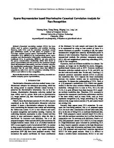
Established communication link Reflected RadCom signal Car equipped RadCom with RadCom signal node Interference signal
Interferer
Figure 1: RadCom network in ITS applications [19].
with classical methods. Furthermore, sensitive analysis of threshold factor is provided for the Doppler frequency detector, which corresponds to the computational efficiency in different scenarios. The rest of this paper is organized as follows. In Section 2, we present the radar model and problem statement for the RadCom network. Section 3 describes the SR-based rangeDoppler signal processing approach for the RadCom network with the proposed multiusers access mechanism. Simulation results for radar performance analysis and comparison with classical methods are presented in Section 4. Finally, concluding remarks are drawn in Section 5.
2. Radar Model and Problem Statement In this paper, we consider a simplified model for RadCom network system with several cooperative RadCom nodes. Each RadCom node uses its omnidirectional antenna to transmit OFDM signals modulated by arbitrary information and receives reflected signals by a directional antenna. Meanwhile, signals transmitted by this node arrive at the receiving ends of other nodes for communication purposes. If two or more nodes transmit signals simultaneously, their signals are required to be differentiated by using a multiaccess technique. 2.1. RadCom Network Setup. Figure 1 [19] shows a typical RadCom network. Those nodes are capable of maintaining communication links between themselves and maintaining active sensing of the target scene using the backscattered signals. The communication and radar functionalities occur simultaneously. The RadCom signal is used for both communications among RadCom nodes and target localization. Specifically, the RadCom signal is transmitted from the car on the left which establishes a communication link with the car on the upper right. At the same time, this RadCom signal is reflected by some objects, that is, the car on the middle right side. The car on the left receives the reflected signal and estimates the range and velocity of the target by using related signal processing methods. Simultaneously, signals from other RadCom nodes, that is, the car on the bottom right, are received by the car on the left and interfere with the receiver. A mechanism similar to general OFDMA is used for multiuser access. Each RadCom node needs to know the
International Journal of Antennas and Propagation
3 Transmit enabling switch
Transmitter PSK/QAM modulation
Data
OFDM modulation
Reference signal
Transmitter
Channel allocation
Radar radio environment (Radar targets, other RadCom nodes)
Active Subcarrier
Receiver Target parameters
Range-Doppler estimation
Data output
PSK/QAM demodulation
Divide OFDM demodulation
Figure 2: RadCom node architecture. −30
1
PSD (dB/rad/sample)
−40
0.5
−50 −60 −70
0
−80
200
400 600 Subcarrier number
800
1000
0
2 4 Normalized frequency (rad/sample)
(a)
6
(b)
Figure 3: (a) Uniform random subcarrier allocation; (b) power spectrum density (PSD) of the transmitted signal.
instantaneous channel occupancy information when they transmit signals. Instead of using periodical or grouped subcarriers, the idea in this paper is to choose a random set of subcarriers for each node. Nevertheless, the subcarriers allocated to each user are not specified by the user itself entirely but preassigned by the RadCom network protocol and selected by the user with appropriate broadcast protocols. The problem of channel overlap between users can be avoided in this way. In this paper, we focus on the related radar signal processing method. Issues like broadcast protocols can be solved by the existing wireless communication protocols [33]. 2.2. RadCom Node Transmitter Subsystem. Figure 2 presents the internal architecture of a single RadCom node. A channel allocation module corresponding to the subcarrier allocation protocol is introduced in order to provide subcarrier information for both transmitter and receiver of each user. When there are 𝑀 users, each user is assigned with 𝐾 randomly selected subcarriers according to a uniform distribution. Let 𝐴 𝑚 denote the set of active subcarrier indices reserved for user 𝑚, so that ⋃𝑀 𝑚=1 𝐴 𝑚 = {1, . . . , 𝐾} and 𝐴 𝑚 ∩ 𝐴 𝑚 = ⌀.
As shown in [34], the random selection of the frequency samples guarantees that the DFT matrix obeys the restricted isometry property (RIP) with high probability, which is necessary for SR-based techniques. The module named Divide is related to the modulation Symbol-Domain method, which is used for eliminating the modulation information while performing radar sensing functions. More details are presented in Section 3. Figure 3 shows a case of random selected subcarrier allocation and its corresponding power spectrum of the transmitted signal. In this case, the number of subcarriers is 64, which is one-sixteenth of the number of total available subcarriers. An OFDM symbol can be considered as the sum of multiple orthogonal signal-carrier signals in the symbol duration 𝑇. Each subcarrier is modulated with different transmit data belonging to a Quadrature Amplitude Modulation (QAM) or phase-shift keying (PSK) constellation map. The transmitted time-domain baseband signal of the 𝑚th user is expressed by 𝑥𝑚 (𝑡) = ∑ ∑ 𝑑𝑘 [𝑛] 𝑝𝑇 (𝑡 − 𝑛𝑇) 𝑒𝑗2𝜋(𝑡−𝑛𝑇)𝑓𝑘 , 𝑛 𝑘∈𝐴 𝑚
(1)
4
International Journal of Antennas and Propagation
where 𝑛 denotes the number of OFDM symbols. 𝑑𝑘 [𝑛] denotes the transmitted data with the 𝑘th subcarrier of the 𝑛th symbol. 𝑇 is the OFDM symbol period; 𝑝𝑇 (𝑡 − 𝑛𝑇) is the shaping filter of the transmitter; 𝑓𝑘 is the frequency of the 𝑘th subcarrier. For OFDM modulation, the shaping filter is a timedomain rectangular filter, which includes the duration of cyclic prefix (CP) denoted by 𝑇CP . CP is important for OFDM modulation to eliminate the intersymbol interference (ISI) due to multipath wireless channels and is inserted between adjacent OFDM symbols. The shaping filter of the OFDM transmitter can be expressed as {1, 𝑡 𝑝𝑇 (𝑡) = rect ( ) = { 𝑇 0, {
0 ≤ 𝑡 ≤ 𝑇,
(2)
otherwise,
where 𝑇 = 𝑇0 + 𝑇CP . 𝑇0 is the duration of OFDM symbol except the cyclic prefix. 2.3. Target Channel Model. We consider the equivalent baseband models of signal processing in this paper for convenient. Let 𝑥 represent a particular sequence of OFDM waveforms to be used for transmission, and 𝑛 represents the additive white Gaussian noise (AWGN). Suppose there are 𝐻 nonfluctuating far-field targets (according to the Swerling-0 model [35]) in the illuminating area of one RadCom node with distances 𝐻 {𝑅ℎ }𝐻 ℎ=1 and relative velocities of {Vℎ }ℎ=1 . Correspondingly, the delay and Doppler shift of each target can be expressed as 𝜏ℎ = 2𝑅ℎ /𝑐 and 𝑓𝐷,ℎ = 2𝑓𝐶Vℎ /𝑐, respectively, where 𝑐 is the speed of light and 𝑓𝐶 is the carrier frequency of OFDM signals. By discarding the cyclic prefix samples in the receiver, the received time-domain signal of the 𝑚th user can be expressed as 𝐻
× 𝑒𝑗2𝜋(𝑡−𝑛𝑇−𝜏ℎ )𝑓𝑘 𝑒𝑗2𝜋𝑓𝐷,ℎ 𝑡 + 𝑤 (𝑡) , where 𝑤(𝑡) is additive white Gaussian noise (AWGN) with zero-mean and variance 𝜎2 . 𝑎ℎ is the attenuation of the ℎth target affected by path loss, scattering, and processing gains. 2.4. RadCom Node Receiver Subsystem. The received baseband signal is passed to an OFDM demodulator as illustrated in Figure 2, which converts the signal from time domain to frequency domain. On account that the information is modulated in frequency domain with OFDM, this essentially acquired the information after channel distortion as ̂ [𝑛] = ∫ 𝑑 𝑘
(𝑛+1)𝑇
𝑡=𝑛𝑇
𝑦 (𝑡) 𝑝𝑅 (𝑡 − 𝑛𝑇) 𝑒
−𝑗2𝜋(𝑡−𝑛𝑇)𝑓𝑘
𝑑𝑡,
(4)
where 𝑝𝑅 (𝑡) = rect(𝑡/𝑇) is the matched filter in the receiver corresponding to the shaping filter in the transmitter. For the
OFDM modulation, the matched filter and shaping filter have the same form, which has the rectangular window in time domain. Then, the demodulated data is fed into the communication module or radar module alternatively. Note that the demodulation process related to the radar module does not consider any equalization in time domain or in frequency domain. The timing synchronization is the same as the transmitter in order to obtain the time reference. Next we introduce details of our radar signal processing in Section 3.
3. SR-Based Range-Doppler Processing In this section, we develop a method for jointly estimating the range and Doppler shift based on SR technique in the multiuser scenario. OFDM-based RadCom system was first developed in [19] and an element-wise division technique was proposed for obtaining the channel information. DFT is used to estimate the range and Doppler frequency shift independently. In order to realize radar sensing functions more robustly, a range-Doppler processing framework is constructed combined with SR method. For the scope of this paper, the following assumptions are made: (1) The two-way propagation time of the reflected signal for the furthest target is smaller than the cyclic prefix duration in order to guarantee the orthogonality between the received signals and the transmitted signals. (2) The center frequency of the signal is much larger than the total bandwidth, so that the Doppler shift is assumed to be constant over the entire bandwidth. (3) The position of the target is assumed to be constant during the total integration period; that is, the target’s radial velocity is small enough and the radial displacement can be neglected while processing. (4) The Doppler shift of the target is much smaller than the subcarrier space, which is also for guaranteeing the orthogonality of the signals as much as possible. With these assumptions, the demodulated symbol of the reflected OFDM signal can be written as 𝐻
where 𝑤𝑘 [𝑛] is the additive noise related to the 𝑛th symbol in the 𝑘th subcarrier. Let D denote a new matrix with its entries ̂ [𝑛] and the element-wise division of the received symbols 𝑑 𝑘 transmitted symbols 𝑑𝑘 [𝑛] [19], given as 𝐷0,0 [ 𝐷 [ 1,0 [ D=[ . [ . [ .
𝐷0,1
⋅⋅⋅
𝐷1,1
⋅⋅⋅
.. .
d
𝐷0,𝑁−1
𝐷1,𝑁−1 ] ] ] ], .. ] . ]
[𝐷𝐾−1,0 𝐷𝐾−1,1 ⋅ ⋅ ⋅ 𝐷𝐾−1,𝑁−1 ]
(6)
International Journal of Antennas and Propagation
5
̂ [𝑛]/𝑑 [𝑛] = ∑𝐻 𝑎 𝑒−𝑗2𝜋𝜏ℎ 𝑓𝑘 𝑒𝑗2𝜋𝑓𝐷,ℎ 𝑛𝑇 + where 𝐷𝑘,𝑛 = 𝑑 𝑘 𝑘 ℎ=1 ℎ 𝑤𝑘 [𝑛]/𝑑𝑘 [𝑛]. Let X denote a new matrix with its each nonzero element 𝑋𝜏,𝑓𝐷 corresponding to a reflecting target or clutter. The amplitude of each nonzero element represents the reflection strength 𝑎ℎ of the ℎth target, given as 𝑋𝜏,𝑓𝐷
{𝑎ℎ , ={ 0, {
if 𝜏 = 𝜏ℎ , 𝑓𝐷 = 𝑓𝐷,ℎ , otherwise.
(7)
symbols ỹ, x̃, and w ̃ to indicate the signal components for 𝑛th equation in (12), respectively, given as 𝑛 ỹ = F𝐻 𝐴 Y𝐴 ,
(13a)
𝑛 x̃ = F𝐻 𝐴 F𝐴 X ,
(13b)
𝑛 w ̃ = F𝐻 𝐴 W𝐴 .
(13c)
Then the 𝑛th equation in (12) can be written as ỹ = x̃ + w ̃.
Then, (6) can be represented as D = F𝐾 XF𝐻 𝑁 + W,
(8)
where F𝐾 and F𝑁 represent Fourier transform matrices with different sizes of 𝐾 × 𝐾 and 𝑁 × 𝑁, respectively. W is the additional noise matrix. (⋅)𝐻 denotes the conjugate transpose of a matrix. According to the definition of Kronecker product, (8) can be expressed in vector form, given as vec (D) = (F𝐾 ⊗ F𝑁) vec (X) + vec (W) ,
(9)
where ⊗ denotes Kronecker product of two matrices. Equation (9) corresponds to the vectorization processing of two-dimensional SR in a traditional manner, that is, in [36]. Although each node occupies all time for communication and sensing, the amount of OFDM symbols are not undersampled. Considering factors of computational efficiency, we only take advantage of SR in one dimension, namely, the range estimation procedure. As for the Doppler offset estimation procedure, the classical spectrum estimation method and a Doppler frequency detector are employed. Formally, performing DFT on each row of matrix D in (8), one has ̃ Y = DF𝑁 + WF𝑁 = F𝐾 XF𝐻 𝑁 F𝑁 + WF𝑁 = F𝐾 X + W. (10) The 𝑛th column of a matrix is denoted as (⋅)𝑛 . Then, one has 𝑛
̃ , 𝑛 ∈ {1, 2, . . . , 𝑁} . Y 𝑛 = F𝐾 X 𝑛 + W
(11)
Considering that the active subcarrier set is assigned by 𝐴. There are only a small number of rows in matrix Y to be effective, while other rows correspond to inefficient transmitted data and are invalid after division processing. The number of active subcarriers corresponds to active subcarrier set 𝐴 that is denoted by 𝐾𝐴. Let Y𝐴 denote the submatrix corresponding to the active subcarrier set 𝐴. The Fourier transform matrix becomes F𝐴 in the same manner. Hence, ̃ 𝑛 , 𝑛 ∈ {1, 2, . . . , 𝑁} . Y𝑛𝐴 = F𝐴 X𝑛 + W 𝐴
(12)
In (12), there are 𝑁 equations. 𝑁 equals the number of OFDM symbols for integration and is large with a long integration period. To this end, an additional detector is applied to (12) and only a small number of equations are reserved among all 𝑁 equations. In order to maximize the detection performance, a matched filter is performed on each equation. Here we use
(14)
The detection problem of the 𝑘th element in x̃ is formulated as ̃ ̃ 𝐻0 : 𝑦 (15a) 𝑘 = 𝑤𝑘 , ̃ ̃ ̃𝑘 . 𝐻1 : 𝑦 (15b) 𝑘 = 𝑥𝑘 + 𝑤 Then, a threshold detector can be used to perform the target detection in each Doppler frequency, namely, 𝐻1 ̃ ∑ 𝑢 (𝑦 𝑘 − 𝜆 0 𝜎) ≷ 1, 𝐻0
𝑘∈𝐴
(16)
where 𝑢(⋅) represents unit step function; 𝜎 is the variance of the noise after matched filter; and 𝜆 0 is the threshold factor that can be used to adjust the threshold to control the detection and false alarm probability. In this paper, a cell average technique is used to estimate the noise variance adaptively, given as ̂=√ 𝜎
𝐾𝐴 𝑁 2 ∑𝑛=1 ∑𝑘=1 (̃y)𝑘,𝑛 . 𝜋 𝑁𝐾𝐴
(17)
To remove unnecessary dismissal, a smaller threshold factor is used, especially with low signal-to-noise ratios. However, a smaller threshold factor will increase the remaining equations to solve. Since this is only an intermediate step followed by the SR-based solving algorithm, only computational complexity is affected. By this way, the multiple variable estimation problem in (8) becomes at most 𝑁 parallel one-dimensional estimation process. Since the number of targets is always small, 𝑙0 norm of X𝑛 satisfies ‖X𝑛 ‖0 ≪ 𝐾. Then, the estimation of X𝑛 can be obtained by solving the following optimization problem: ̂𝑛 = arg min X 𝑛 X
s.t.
𝑛 X 0 𝑛 𝑛 Y𝐴 − F𝐴X 2 ≤ 𝜎.
(18)
There are a wide variety of approaches to solve (18), including greedy algorithms, 𝑙1 norm minimization basis pursuit denoising (BPDN), and iterative thresholding [37–39]. In the high noisy environment, BPDN usually performs much better than the others [39]. The Homotopy algorithm can solve the BPDN problem more efficiently with lower computational complexity compared with the classical convex optimization algorithms, especially when the size of the problem is large [36].
6
International Journal of Antennas and Propagation
K OFDM Rearrangement Received demodulation Div signal
Doppler frequency detection
Doppler estimation
M Parallel SR reconstruction (range estimation)
1 M
Reference symbol 1
K 1
1
Ran ge
D
ft shi ler p op
Figure 4: The flow chart of the range-Doppler processing.
Table 1: OFDM RadCom system parameters. Parameter Carrier frequency Subcarrier spacing OFDM symbol length Cyclic prefix length Bandwidth Symbol number for integration
Value 5.9 GHz 90.909 kHz 11 us 1.375 us 93.1 MHz 256
In the simulation, we use the BPDN algorithm to estimate ̂𝑛 . Figure 4 shows the flow chart of the the sparse vector X range-Doppler processing. A one-dimensional BPDN algorithm is used in the last step concurrently. As can be seen at the end of Section 4, the threshold factor 𝜆 0 can influence the performance of the Doppler frequency detector, especially when SNR is ultralow. In the following, it is assumed that 𝜆 0 is small enough for all simulations except the last one concentrated on the detector performance, in order to guarantee that these results are optimal and are not influenced by other factors.
4. Simulation Results and Discussion In this section, simulation results are presented for performance evaluation. The proposed processing method is compared with the classical processing methods. Section 4.1 introduces the simulation scenarios. Sections 4.2 and 4.3 present simulation results of target detection performance without and with multiuser interference in an AWGN environment, respectively. Section 4.4 analyzes the influence of the threshold factor on the performance of the Doppler frequency detector. 4.1. Simulation Scenarios. The RadCom system parameters are shown in Table 1 as in [18]. The received OFDM symbols are processed with the range-Doppler estimation algorithm without performing any previous channel equalization or decision. The OFDM signal fulfills certain requirements for division operation in (6) in order to be correct. Specifically, deorthogonalization needs to be avoided to make sure that ̂ [𝑛] is correctly aligned to the corresponding 𝑑 [𝑛]. In this 𝑑 𝑘 𝑘 case, the time delay 𝜏ℎ is smaller than 𝑇CP , which corresponds to a maximum target distance of about 206 m.
Also, the maximum Doppler shift is required to stay smaller than the subcarrier spacing. When the radial velocity of the target is 200 km/h, the Doppler shift is approximately 2.2 kHz, which is only 2.4% of the subcarrier spacing. In the following simulations, the distance and radial velocity of targets are assumed to be in the range within (0, 200] m and [−2.2, 2.2] kHz separately for unambiguity and guaranteeing of orthogonality, and all targets are located on the grids of range-Doppler processing. According to the OFDM system parameterization, the range resolution is about 1.61 m, and the Doppler frequency resolution is about 315 Hz. 4.2. Radar Performance without Interference. When there is no interference, that is, only one node in active operating mode, the radar performance is only influenced by SNR and the number of active subcarriers. First, it is assumed that only one target exists with delay and Doppler shift randomly locates in the assumed unambiguous region. The peak-to-side-lobe ratio (PSLR), which describes the ratio between the main peak and maximum sidelobe value, is used for performance analysis with different SNRs. The side-lobe value is mainly caused by Fourier sidelobes since the modulated information is eliminated by using the modulation Symbol-Domain method [19]. Periodogram is employed with classical modulation Symbol-Domain method. Since works in [19] have proved that the modulation Symbol-Domain method is superior to the matched filter with OFDM waveform under the assumed scenes, we only consider the classical modulation Symbol-Domain method for performance comparison. Hereinafter, the classical modulation Symbol-Domain method is expressed as “SymbolDomain” and the proposed SR-based method is expressed as “Symbol-Domain SR” for simplicity. All the results are obtained by averaging over 1000 independent trials. Figure 5 presents the PSLR versus SNRs. Different lines present the results obtained by using different methods with different number of subcarriers. It is seen that, in the double logarithmic representation, the PSLR of the proposed Symbol-Domain SR method increases linearly with SNR. PSLRs with less subcarrier number are slightly higher. This phenomenon is mainly caused by the lower noise level with less sampled data when the number of subcarriers is smaller. On the contrary, all PSLRs of classical Symbol-Domain method with partial subcarriers have a performance bottleneck. That is, when the SNRs of the received signal increases, the PSLRs tend to be constant. In addition, when the
International Journal of Antennas and Propagation
7
60
1 70
50 40
65
30
60
20
25
30
Normalized amplitude
Peak-to-side-lobe ratio (dB)
70
0.8 0.6 0.4 0.2 0
20
400 10 −30
−20 −10 0 10 20 Signal-to-noise ratio (dB)
30
40
Symbol-Domain SR, KA = 64 Symbol-Domain SR, KA = 128 Symbol-Domain SR, KA = 256 Symbol-Domain SR, KA = 512 Symbol-Domain SR, KA = 1024 Symbol-Domain, KA = 64 Symbol-Domain, KA = 128 Symbol-Domain, KA = 256 Symbol-Domain, KA = 512 Symbol-Domain, KA = 1024
Figure 5: Achievable peak-to-side-lobe ratios of different methods in a noisy single user scenario.
−100
0
−50
0
50
ler grid Dopp
1 0.8 0.6 0.4 0.2 0 400
Ran 200 ge g rid
subcarrier number decreases, the PSLR of classical method decreases, which is contrary to the proposed method. When all available subcarriers are used by a single user, the performance of Symbol-Domain SR method is equivalent to the classical Symbol-Domain method. Figure 6 shows the range and Doppler shift estimation of both Symbol-Domain and Symbol-Domain SR methods in one experiment of single target with SNR being −20 dB and the number of subcarriers equals 128. Range and Doppler grid corresponding to the sampling number in their respective dimensions are employed to represent the relative estimation performance. It is observed that the Symbol-Domain method has higher side-lobes compared to that achieved by using the Symbol-Domain SR method. Meanwhile, the side-lobes are mainly located in the range dimension. The difference of range side-lobes is mainly caused by the partial use of subcarriers, which is equivalent to undersampling in frequency domain corresponding to the range dimension. In order to verify the performance with multiple targets, the receiver operating characteristic (ROC) is computed in simulation with five targets having the same SNRs. The first two targets belong to the same range bin. The other two targets belong to another Doppler bin, and the fifth target is chosen to have random range and Doppler shift different from the first four. All five targets are located randomly in the assumed unambiguous range. For convenient analysis, the SNR is chosen to be −33 dB, which provides clear results. Since the first target and the second target are exchangeable,
100
(a)
Normalized amplitude
−40
Ran 200 ge g rid
−100
0
−50
0
50
100
ler grid Dopp
(b)
Figure 6: Range and Doppler estimation of single target when SNR = −20 dB. (a) Symbol-Domain and (b) Symbol-Domain SR.
and the same to the third target and the fourth target, we only consider the detection of three targets, that is, the first, the third, and the fifth target. All the results are obtained by averaging over 1000 independent trials. Figure 7 shows the ROC curves for different parameters. In Figures 7(a) and 7(b), ROC curves are presented for different targets when the number of subcarriers is 64 and 128. As can be seen that the performance of the third target is much worse, this corresponds to the two targets with the same range bin. As for the first and the fifth target, the ROC curves behave similarly. In Figures 7(c) and 7(d), ROC curves are presented for different subcarrier numbers with the first and the third targets. For the ROCs of the first target, which corresponds to the two targets with the same Doppler bin, there is not obvious performance reduction. However, when the number of subcarriers decreases, the detection performance of the third target reduces. The main reason is that the high side-lobes are located in the same range bin relative to the real target. In a word, targets with the same range bin may cause shadowing effect to each other and result in performance reduction.
8
International Journal of Antennas and Propagation
0.95
0.95
0.9
0.9 PD
1
PD
1
0.85
0.85
0.8
0.8
0.75
0
0.5 Pfa
0.75
1
0
Symbol-Domain (the 1st target) Symbol-Domain SR (the 1st target) Symbol-Domain (the 3rd target) Symbol-Domain SR (the 3rd target) Symbol-Domain (the 5th target) Symbol-Domain SR (the 5th target)
0.5 Pfa
1
Symbol-Domain (the 1st target) Symbol-Domain SR (the 1st target) Symbol-Domain (the 3rd target) Symbol-Domain SR (the 3rd target) Symbol-Domain (the 5th target) Symbol-Domain SR (the 5th target)
(a) 𝐾𝐴 = 64
(b) 𝐾𝐴 = 128
0.95
0.95
0.9
0.9 PD
1
PD
1
0.85
0.85
0.8
0.8
0.75
0
0.5 Pfa Symbol-Domain (KA = 64) Symbol-Domain SR (KA = 64) Symbol-Domain (KA = 128) Symbol-Domain SR (KA = 128) Symbol-Domain (KA = 256) Symbol-Domain SR (KA = 256) (c) The first target
1
0.75
0
0.5 Pfa
1
Symbol-Domain (KA = 64) Symbol-Domain SR (KA = 64) Symbol-Domain (KA = 128) Symbol-Domain SR (KA = 128) Symbol-Domain (KA = 256) Symbol-Domain SR (KA = 256) (d) The third target
Figure 7: Receiver operating characteristic (ROC) curves for targets with different number of subcarriers.
4.3. Radar Performance with Multiuser Interference. In order to further investigate the performance in the presence of multiuser interference, simulations are performed with various interference levels and different interference parameters. In order to investigate the influence of imperfect timing and carrier frequency synchronization, simulations with different timing shift and different carrier frequency shifts are performed. First, the signal-to-interference ratio (SIR) is
fixed at −40 dB. Different timing and carrier frequency shifts are used to illustrate the influences of the imperfect synchronization intuitively. Then, different SIRs are considered with several timing and carrier frequency shifts. All the results are obtained by averaging over 1000 independent trials. Figure 8(a) shows simulation results for the PSLR dependent on the timing shift of the interferer, while the carrier frequency is assumed to be accurate. When the time shift is
International Journal of Antennas and Propagation
9
50
Peak-to-side-lode ratio (dB)
45 40 35 30 25 20 15 10 5 0
0
0.2
0.4
0.6
0.8
1
1.2
Relative timing offset (×T)
Symbol-Domain Symbol-Domain SR (a)
Figure 8(b) shows the PSLR versus the signal-to-interference ratio and the timing shift. It can be seen that a slight timing shift leads to an obvious performance reduction. When the timing shift increases, the performance is decreased with the increase of the SIR. This behavior is the same to the Symbol-Domain and Symbol-Domain SR methods but with different levels. Similarly, Figure 9(a) shows the simulation results for the PSLR dependent on the frequency shift of the interference while the timing synchronization is assumed to be perfect. The achievable PSLR of the proposed method degrades with the increasing frequency shift of the interference. When the frequency shift is about 4500 Hz, which corresponds to a radial velocity of about 412 km/h, the PSLR degradation is nearly 20 dB. Nevertheless, the PSLR of Symbol-Domain SR method still outperforms the classical method nearly 17 dB. Figure 9(b) shows the PLSR as a function of the signal-tointerference ratio and the frequency shift. The curves show the same characteristics as the analysis in Figure 8(b) for timing shift analysis.
50
Peak-to-side-lode ratio (dB)
45 40 35 30 25 20 15 10 5 0
−70
−60
−50 −40 −30 −20 −10 Signal-to-interference ratio (dB)
Figure 8: Peak-to-side-lobe ratio with multiuser interference when timing offset exists. (a) PSLR versus different relative timing offset when SIR = −40 dB. (b) PSLR versus different SIRs.
smaller than the duration of the cyclic prefix, there is no PSLR reduction. In this case, the duration of cyclic prefix is 0.125𝑇. For higher timing shifts, a PSLR drop occurs. This is caused by the fact that the orthogonality of the OFDM symbols among different users is damaged. As for the classical SymbolDomain method, the effect of deorthogonalization does not appear. It is because that the high side-lobes are mainly caused by the undersampling, instead of the deorthogonalization.
4.4. Sensitivity of Threshold Factor for Doppler Frequency Detector. We assume that there are five targets with the same signal-to-noise ratio but located with completely random range and Doppler frequency shifts in the assumed unambiguity ranges. Figure 10 shows the variations of the detection probability and false alarm probability versus the threshold factors for different signal-to-noise ratios when the subcarrier number is 64. It is seen that the change of the SNR does not influence the false alarm probability. But when the SNR increases, the detection probability behaves quite differently. When the threshold factor 𝜆 0 is selected to make the detection probability equal to 0.95, false alarm probabilities are different at different SNRs. When the SNR equals −35 dB, the false alarm probability is only 0.0321. This indicates that only 3.21 percent of the total computational burden is extra added. However, when the SNR equals −40 dB and −45 dB, the additional computational burden increases to 83.87 percent and 93.18 percent, respectively. In a word, when the SNR is ultralow, the Doppler frequency detector has no effect on decreasing calculation amount. Otherwise, when the SNR is high, the curves of detection probability and false alarm probability separate in a wide range of the threshold factor. An appropriate value of the threshold factor can be chosen in order to exclude the frequencies with no target. According to the simulation results, for a certain detection probability, the threshold factor is related to the SNR directly. Applicable approaches of estimating actual SNR are needed for choosing the correct threshold factor value, but it is beyond the scope of this paper.
5. Conclusions In this paper, a simple multiuser access scheme with a random subcarrier allocation mechanism has been investigated in RadCom networks. The corresponding SR-based signal processing method is derived. Instead of allocating subcarriers periodically or sequentially with blocks, the proposed scheme
10
International Journal of Antennas and Propagation
45
1 0.95 0.9
40
0.8
35 30
Probability
Peak-to-side-lobe ratio (dB)
50
25 20
0.4
15
0.3
10
0.2
5
0.1
0
0 0
1000
2000 3000 4000 Carrier frequency offset (Hz)
5000
Pfa = 0.0321 (SNR = −35 dB)
0
1
2
3
PD , SNR = −30 dB Pfa , SNR = −30 dB PD , SNR = −35 dB Pfa , SNR = −35 dB
Symbol-Domain Symbol-Domain SR (a)
50
4 𝜆0
5
6
7
8
PD , SNR = −40 dB Pfa , SNR = −40 dB PD , SNR = −45 dB Pfa , SNR = −45 dB
Figure 10: Detection and false alarm probability versus threshold factor 𝜆 0 .
Figure 9: Peak-to-side-lobe ratio with multiuser interference when carrier frequency offset exists. (a) PSLR versus different frequency offset when SIR = −40 dB. (b) PSLR versus different SIRs.
fully utilizes the available bandwidth for radar sensing in a completely random manner. Since the total bandwidth occupied by each user does not decrease, the accuracy of radar sensing is the same as the traditional OFDM radar. A parallel structured radar signal processing framework is proposed
with a Doppler frequency detector to reduce computational complexity. The advantage of the proposed scheme is that it introduces no range or Doppler ambiguity and allows more users to work simultaneously in the same bandwidth compared with the traditional interleaved subcarrier allocation manner. Simulation results show that the proposed method based on SR is superior to the classical Symbol-Domain method in all SNRs with/without multiuser interferences in the assumed unambiguity ranges. The Doppler frequency detector is highly effective for most SNRs, except when the SNR is ultralow. The scheme proposed in this paper allows more users to work simultaneously without additional bandwidth occupation. With the increasingly crowded spectrum, this can help to further develop integrated RadCom systems in multiuser scenarios, for example, intelligent transportation systems for road safety with high system efficiency.
Conflicts of Interest The authors declare that they have no conflicts of interest and received funding did not lead to any conflicts of interest regarding the publication of this paper.
Acknowledgments The research reported in this article was supported in part by the National Natural Science Foundation of China (61661028, 61561034, 61461030, and 61661032), the Key Programs for Young Natural Science Foundation of Jiangxi Province (20152ACB21008), Young Scientist of Jiangxi Province (20142BCB23001), and the Natural Science Foundation of Jiangxi Province (20161BAB212038).
International Journal of Antennas and Propagation
11
References [1] D. Ciuonzo, A. De Maio, G. Foglia, and M. Piezzo, “Intrapulse radar-embedded communications via multiobjective optimization,” IEEE Transactions on Aerospace and Electronic Systems, vol. 51, no. 4, pp. 2960–2974, 2015. [2] L. Han and K. Wu, “Joint wireless communication and radar sensing systems—state of the art and future prospects,” IET Microwaves, Antennas and Propagation, vol. 7, no. 11, pp. 876– 885, 2013. [3] A. Hassanien, M. G. Amin, Y. D. Zhang, and F. Ahmad, “Signaling strategies for dual-function radar-communications: an overview,” IEEE Aerospace and Electronic Systems Magazine, vol. 31, no. 10, pp. 36–45, 2016. [4] W. Wiesbeck, L. Sit, M. Younis, T. Rommel, G. Krieger, and A. Moreira, “Radar 2020: the future of radar systems,” in Proceedings of the IEEE International Geoscience and Remote Sensing Symposium (IGARSS ’15), pp. 188–191, Milan, Italy, July 2015. [5] A. Hassanien, M. G. Amin, Y. D. Zhang, and F. Ahmad, “Dualfunction radar-communications: information embedding using sidelobe control and waveform diversity,” IEEE Transactions on Signal Processing, vol. 64, no. 8, pp. 2168–2181, 2016. [6] M. Mozaffari, W. Saad, M. Bennis, and M. Debbah, “Unmanned aerial vehicle with underlaid device-to-device communications: performance and tradeoffs,” IEEE Transactions on Wireless Communications, vol. 15, no. 6, pp. 3949–3963, 2016. [7] W. Zhao and S. Wang, “Resource sharing scheme for deviceto-device communication underlaying cellular networks,” IEEE Transactions on Communications, vol. 63, no. 12, pp. 4838–4848, 2015. [8] R. Bishop, Intelligent Vehicle Technology and Trends, Artech House, Norwood, Mass, USA, 2005. [9] R. H. Cager Jr., D. T. LaFlame, and L. C. Parode, “Orbiter Kuband integrated radar and communications subsystem,” IEEE Transactions on Communications, vol. 26, no. 11, pp. 1604–1619, 1978. [10] J. Moghaddasi and K. Wu, “Multifunctional transceiver for future radar sensing and radio communicating data-fusion platform,” IEEE Access, vol. 4, pp. 818–838, 2016. [11] K. Konno and S. Koshikawa, “Millimeter-wave dual mode radar for headway control in IVHS,” in Proceedings of the IEEE MttS International Microwave Symposium Digest, vol. 3, pp. 1261– 1264, Denver, Colo, USA, 1997. [12] L. Han and K. Wu, “24-GHz integrated radio and radar system capable of time-agile wireless communication and sensing,” IEEE Transactions on Microwave Theory and Techniques, vol. 60, no. 3, pp. 619–631, 2012. [13] S. Lindenmeier, K. Boehm, and J. F. Luy, “A wireless data link for mobile applications,” IEEE Microwave and Wireless Components Letters, vol. 13, no. 8, pp. 326–328, 2003. [14] X. Yin, J. Bauwelinck, G. Torfs et al., “Embedded ranging system in ISM band,” Electronics Letters, vol. 44, no. 17, pp. 1043–1045, 2008. [15] S. J. Xu, Y. Chen, and P. Zhang, “Integrated radar and communication based on DS-UWB,” in Proceedings of the 3rd International Conference Ultrawideband and Ultrashort Impulse Signals (UWBUSIS ’06), pp. 142–144, Sevastopol, Ukraine, September 2006. [16] Z. Y. Lin and P. Wei, “Pulse position modulation time hopping ultra wideband sharing signal for radar and communication
[17]
[18]
[19]
[20]
[21]
[22]
[23] [24]
[25]
[26]
[27]
[28]
[29]
[30]
[31]
[32]
system,” in Proceedings of the CIE International Conference on Radar (ICR ’06), pp. 1640–1643, October 2006. G. N. Saddik, R. S. Singh, and E. R. Brown, “Ultra-wideband multifunctional communications/radar system,” IEEE Transactions on Microwave Theory and Techniques, vol. 55, no. 7, pp. 1431–1436, 2007. C. Sturm, Y. L. Sit, M. Braun, and T. Zwick, “Spectrally interleaved multi-carrier signals for radar network applications and multi-input multi-output radar,” IET Radar, Sonar and Navigation, vol. 7, no. 3, pp. 261–269, 2013. C. Sturm and W. Wiesbeck, “Waveform design and signal processing aspects for fusion of wireless communications and radar sensing,” Proceedings of the IEEE, vol. 99, no. 7, pp. 1236– 1259, 2011. J. Fink, M. Braun, and F. K. Jondral, “Effects of arbitrarily spaced subcarriers on detection performance in OFDM radar,” in Proceedings of the 76th IEEE Vehicular Technology Conference (VTC Fall ’12), Qu´ebec, Canada, September 2012. Z. Zhang, Y. Xu, J. Yang, X. Li, and D. Zhang, “A survey of sparse representation: algorithms and applications,” IEEE Access, vol. 3, pp. 490–530, 2015. S. Qaisar, R. M. Bilal, W. Iqbal, M. Naureen, and S. Lee, “Compressive sensing: from theory to applications, a survey,” Journal of Communications and Networks, vol. 15, no. 5, pp. 443– 456, 2013. J. H. G. Ender, “On compressive sensing applied to radar,” Signal Processing, vol. 90, no. 5, pp. 1402–1414, 2010. A. Massa, P. Rocca, and G. Oliveri, “Compressive sensing in electromagnetics—a review,” IEEE Antennas and Propagation Magazine, vol. 57, no. 1, pp. 224–238, 2015. G. Oliveri, P. Rocca, and A. Massa, “Reliable diagnosis of large linear arrays—a Bayesian compressive sensing approach,” IEEE Transactions on Antennas and Propagation, vol. 60, no. 10, pp. 4627–4636, 2012. G. Oliveri, M. Salucci, and A. Massa, “Synthesis of modular contiguously clustered linear arrays through a sparsenessregularized solver,” IEEE Transactions on Antennas and Propagation, vol. 64, no. 10, pp. 4277–4287, 2016. M. Li, G. Zhou, B. Zhao, and T. Quan, “Sparse representation denoising for radar high resolution range profiling,” International Journal of Antennas and Propagation, vol. 2014, Article ID 875895, 8 pages, 2014. O. Bar-Ilan and Y. C. Eldar, “Sub-Nyquist radar via Doppler focusing,” IEEE Transactions on Signal Processing, vol. 62, no. 7, pp. 1796–1811, 2014. C. Liu, F. Xi, S. Chen, Y. D. Zhang, and Z. Liu, “Pulse-doppler signal processing with quadrature compressive sampling,” IEEE Transactions on Aerospace and Electronic Systems, vol. 51, no. 2, pp. 1216–1230, 2015. M. Tello Alonso, P. L´opez-Dekker, and J. J. Mallorqu´ı, “A novel strategy for radar imaging based on compressive sensing,” IEEE Transactions on Geoscience and Remote Sensing, vol. 48, no. 12, pp. 4285–4295, 2010. V. M. Patel, G. R. Easley, D. M. Healy Jr., and R. Chellappa, “Compressed synthetic aperture radar,” IEEE Journal on Selected Topics in Signal Processing, vol. 4, no. 2, pp. 244–254, 2010. N. Anselmi, M. Salucci, G. Oliveri, and A. Massa, “Waveletbased compressive imaging of sparse targets,” IEEE Transactions on Antennas and Propagation, vol. 63, no. 11, pp. 4889–4900, 2015.
12 [33] Y. Zhang and C. Leung, “Cross-layer resource allocation for mixed services in multiuser OFDM-based cognitive radio systems,” IEEE Transactions on Vehicular Technology, vol. 58, no. 8, pp. 4605–4619, 2009. [34] Y. Eldar and G. Kutyniok, Compressed sensing: Theory and Applications, Cambridge University Press, New York, NY, USA, 2012. [35] M. A. Richards, Fundamentals of Radar Signal Processing, McGraw-Hill, New York, NY, USA, 2005. [36] D. L. Donoho and Y. Tsaig, “Fast solution of 𝑙1 -norm minimization problems when the solution may be sparse,” IEEE Transactions on Information Theory, vol. 54, no. 11, pp. 4789– 4812, 2008. [37] R. Giryes and D. Needell, “Greedy signal space methods for incoherence and beyond,” Applied and Computational Harmonic Analysis, vol. 39, no. 1, pp. 1–20, 2015. [38] J. A. Tropp and S. J. Wright, “Computational methods for sparse solution of linear inverse problems,” Proceedings of the IEEE, vol. 98, no. 6, pp. 948–958, 2010. [39] Z. Ben-Haim, Y. C. Eldar, and M. Elad, “Coherence-based performance guarantees for estimating a sparse vector under random noise,” IEEE Transactions on Signal Processing, vol. 58, no. 10, pp. 5030–5043, 2010.